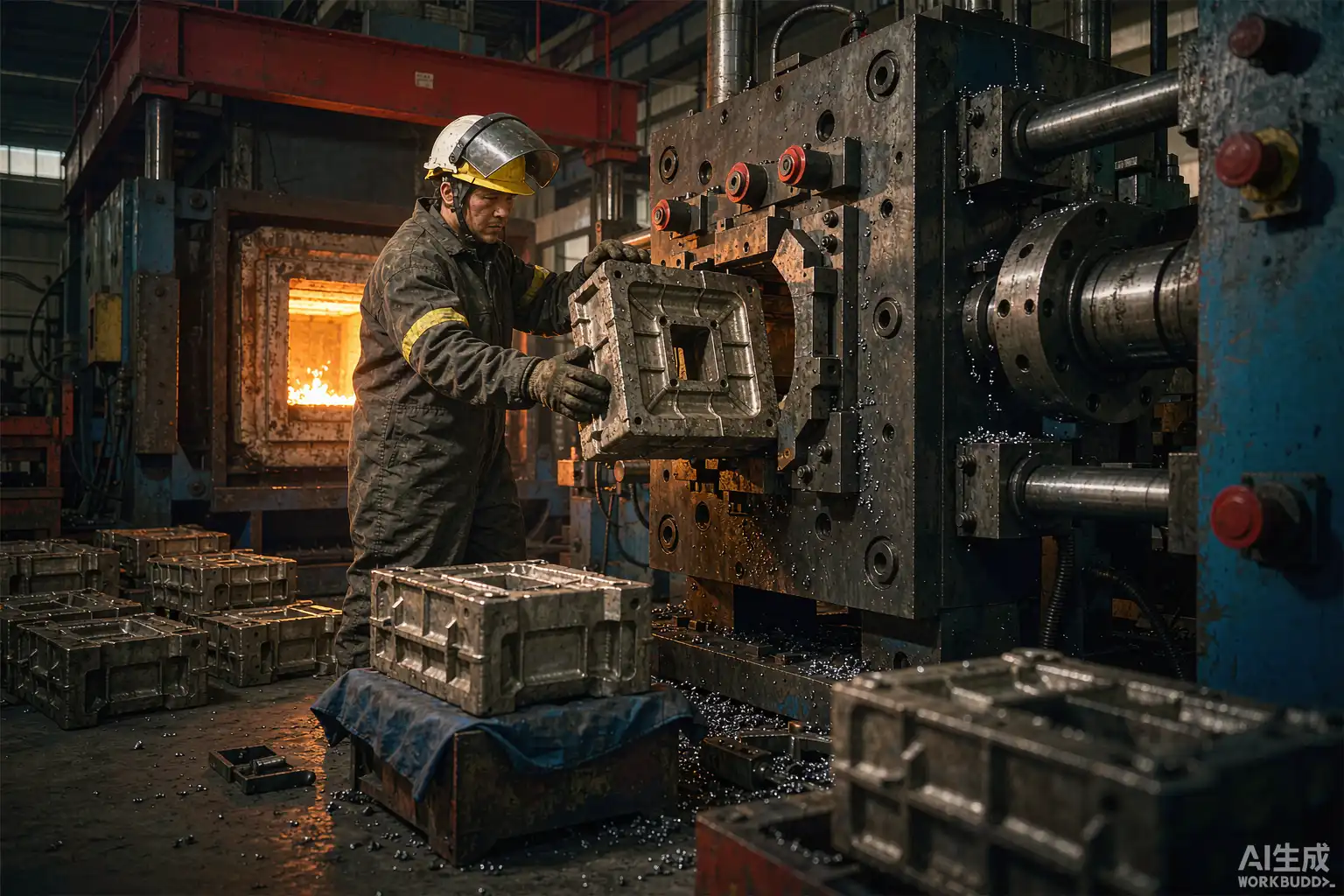
Die casting finishing turns a raw shot with gates, flash, and ejector marks into a part that meets drawing tolerances and surface specs, and doing it automatically keeps every stage of that chain consistent. The goal is simple: remove exactly what the die left behind, and nothing more. Robotic surface finishing for die casting covers the equipment side; this guide walks the process chain itself.
What the Die Leaves Behind
Every die-cast part carries witness marks from the tooling. Gates shear or saw off but leave a stub. Parting lines flash where the die halves meet. Ejector pins leave domes on the casting back. Overflows and vents break away with their own stubs.
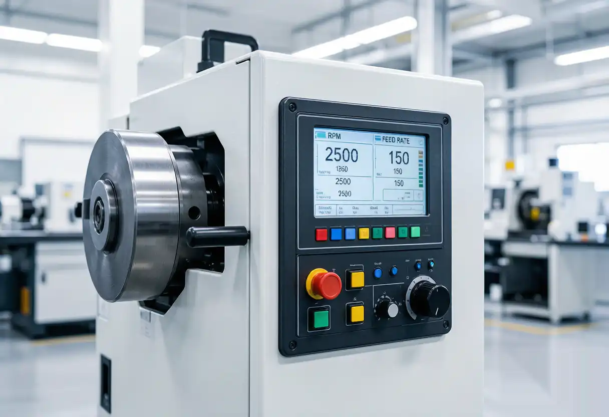
The alloy sets the difficulty. Zinc die-castings flash thin and tear easily, so tools must cut with light force. Aluminium flashes harder and behaves more like a machinable material, tolerating firmer contact and faster feeds.
Thermal distortion matters too. Parts come out at two hundred degrees or more and warp as they cool. Finishing fixtures must locate on post-cooling datums, or every downstream tolerance drifts.
The Finishing Chain, Stage by Stage
A complete automated chain runs five stages between casting and inspection. Each stage hands a cleaner part to the next, so problems surface early instead of compounding.
- Stage 1 — Gate and overflow removal. A saw or punch station takes the thick stubs down to within half a millimetre of the wall.
- Stage 2 — Flash and parting line. A router bit or carbide cutter follows the split line and shaves the flash flush.
- Stage 3 — Ejector and boss blending. A small abrasive tool or brush blends pin domes and boss roots into the surface.
- Stage 4 — Surface grinding. A belt or wheel pass cleans machine marks and evens the texture where the drawing demands it.
- Stage 5 — Wash and inspect. A wash tank clears chips and compound before vision or gauging checks the result.
Not every part needs all five. A zinc cosmetic part may skip stage four; a thick aluminium structural part may double it. The chain is a menu, and the part drawing decides the order.
Choosing a Deburring Method for Each Defect
Defect geometry drives tool choice. A flat flash along a straight split line suits a different tool than burrs hiding inside a pocket. Match them early and the rest of the chain follows.
| Defect | Best Method | Typical Tool | Cycle Impact |
|---|---|---|---|
| Gate stub (thick) | Saw or punch | Carbide saw / press die | 5–10 s |
| Parting-line flash | Routing | 2–4 mm carbide bit | 10–25 s |
| Ejector domes | Blend mill | Ball-nose end mill | 5–15 s |
| Burr in pocket | Robot + small spindle | 1–2 mm bit, 40k RPM | 10–20 s |
| Edge hairlines | Rotary brush | Nylon abrasive brush | 5–10 s |
Zinc parts reward sharp tools and light passes; dull bits smear the alloy instead of cutting it. Aluminium tolerates blunter tools but throws chips that need real extraction.
Grinding Parameters That Hold Tolerance
Grinding after deburring sets the final surface. The parameters below are starting points for typical zinc and aluminium die-cast geometries; your alloy and wall thickness move them up or down.
| Parameter | Zinc Range | Aluminium Range | Why It Matters |
|---|---|---|---|
| Contact force | 5–15 N | 10–25 N | Protects thin walls from thinning |
| Belt speed | 15–25 m/s | 20–30 m/s | Matches cut rate to texture |
| Feed rate | 50–150 mm/s | 80–200 mm/s | Even exposure prevents waviness |
| Pass depth | 0.05–0.15 mm | 0.10–0.25 mm | Keeps stock removal in spec |
| Coolant | Dry or mist | Mist preferred | Stops loading and heat smear |
Stock removal is the number to control. The drawing allows a removal band; exceed it and wall thickness fails, undershoot it and tool marks survive. Log depth per pass and verify on the first article of each lot.
Defects You Will Meet — and What They Tell You
Every recurring defect in die casting finishing has a short list of root causes. Read the table as a triage guide before touching the program.
| Symptom | Likely Cause | Fix |
|---|---|---|
| Chatter marks on ground faces | Fixture looseness or worn belt | Torque fixture; replace belt on schedule |
| Smear instead of cut (zinc) | Dull cutter, high force | Sharp carbide, lighter pass |
| Broken bits in pockets | Path exceeds reach; chips pack | Reroute path; add air blast clearing |
| Wall thickness under spec | Cumulative pass depth | Reduce depth; re-datum tool offset |
| Flash survives at corners | Split line not modelled fully | Add corner waypoints in program |
| Surface varies shift to shift | Compound dose drift | Timed dosing by cycle count |
One habit separates stable cells from unstable ones: when a defect appears, change one variable and re-run ten parts. Shotgun changes hide the true cause and create new defects.
Quality Gates Inside the Chain
Inspection belongs between stages, not only at the end. A gate after deburring catches missing flash cuts before grinding wastes time on a part that will be scrapped anyway.
Practical gates are cheap ones. A vision camera that checks flash presence, a height gauge that checks a critical blend, and a simple presence sensor that confirms the gate stub was removed cover ninety percent of escapes.
Data from these gates feeds the cell controller. Trend the pass rate by stage; when stage three rejects climb, the cutter is wearing. Maintenance follows the trend instead of the calendar.
For automotive and similar customers, log part identity with stage results. End-to-end surface finishing with traceability turns the same data into audit-ready records.
From One Machine to a Full Line
Most plants start with a single deburring machine and add stages as volume grows. The starter machine proves tool life, cycle time, and quality on your real castings before you commit to a line.
The next step is usually a robot cell that strings stages two through four together with part handling between them. Conveyors or pallet shuttles buffer the stages so a slow one never starves the line.
The last step adds wash, inspection, and packaging. At that point the chain runs casting-to-shipping, and labour shifts from finishing to supervision and maintenance.
Scale in that order and each step pays for the next. Skip steps and you automate problems faster than you can solve them.
Working With Your Die Shop
The cheapest finishing is the finishing you avoid. Trim dies that shear gates closer, better die vents that reduce flash, and ejector sleeves that leave lower domes all cut finishing time before any machine runs.
Share finishing data with the die shop each quarter. Which zones always carry excess flash? Which pockets always break tools? Tooling changes that fix those zones repay themselves in finishing hours.
Automatic polishing machines for die-cast components matter when the chain must end in a cosmetic finish. Specify them after deburring and grinding hold tolerance, not before.
Chip and Dust Management Along the Chain
Every stage in the chain makes debris, and the stage after it pays for whatever drifts. Aluminium chips migrate into pockets two stages downstream; zinc dust cakes on fixtures and shifts datums by hundredths that add up.
Attack debris at its source. Air blasts at the tool point clear pockets before the next pass, and extraction hoods shaped to each station — not one generic duct — keep the dust where the filter can reach it.
Fixture cleaning belongs on the schedule, not on the fault list. A thirty-second blow-off between lots prevents the pocket chip that breaks the next bit, and a weekly wash of nest plates resets accumulated drift.
Watch extraction performance as a process variable. Falling airflow at the hood means a loaded filter, and a loaded filter lets dust settle where the next part locates.
First Article and Changeover Discipline
The first article after any change — new lot, new tool, adjusted offset — carries more risk than the next hundred combined. Treat it as a gate, not a formality.
Run the first part at full cycle, then measure the zones that the change touched. A new cutter changes edge geometry everywhere it touches; a new belt changes texture for the first twenty parts until it breaks in.
Log the first-article results by change type. Over months, the log tells you which changes need extra parts before the process stabilises, and which settle instantly — knowledge that shortens every future changeover.
Zinc and Aluminium: Where the Chains Differ
The five stages stay the same across alloys, but their tuning moves. Zinc wants sharper tools, lighter forces, and closer attention to smear; aluminium wants firmer contact, better chip clearance, and cooler cutting.
Belt selection diverges early. A belt that leaves a clean texture on zinc loads up on aluminium within a shift, and the reverse pairing burns the zinc surface. Sharing belts across alloys wastes both.
Extraction requirements differ too. Zinc dust is denser and settles low; aluminium dust is lighter and more voluminous. Plants running both alloys typically split the ducting rather than compromise one for the other.
Zinc and aluminium also disagree on measurement points. Zinc parts show smear before they show wear, so visual sampling catches issues early; aluminium shows neither until dimensions move, so gauge-based sampling carries the load. Plan both into the quality routine from the start.
Die casting finishing rewards plants that treat it as a designed chain: defect map first, tool per defect second, parameters in tables third, and gates between stages throughout. Build it that way and the automation holds tolerance without heroics.
Product names and standards evolve; verify the current edition before specifying.