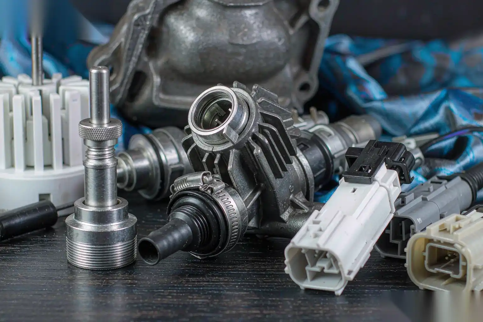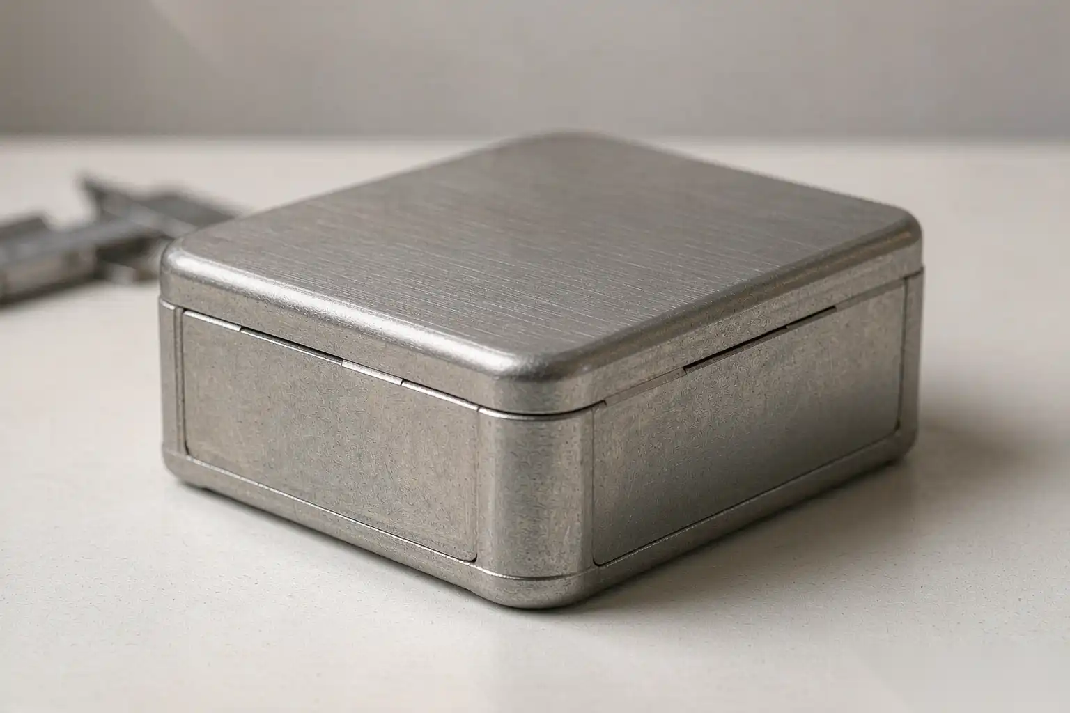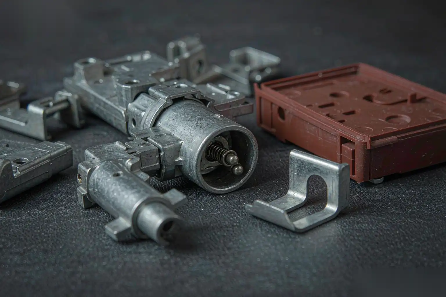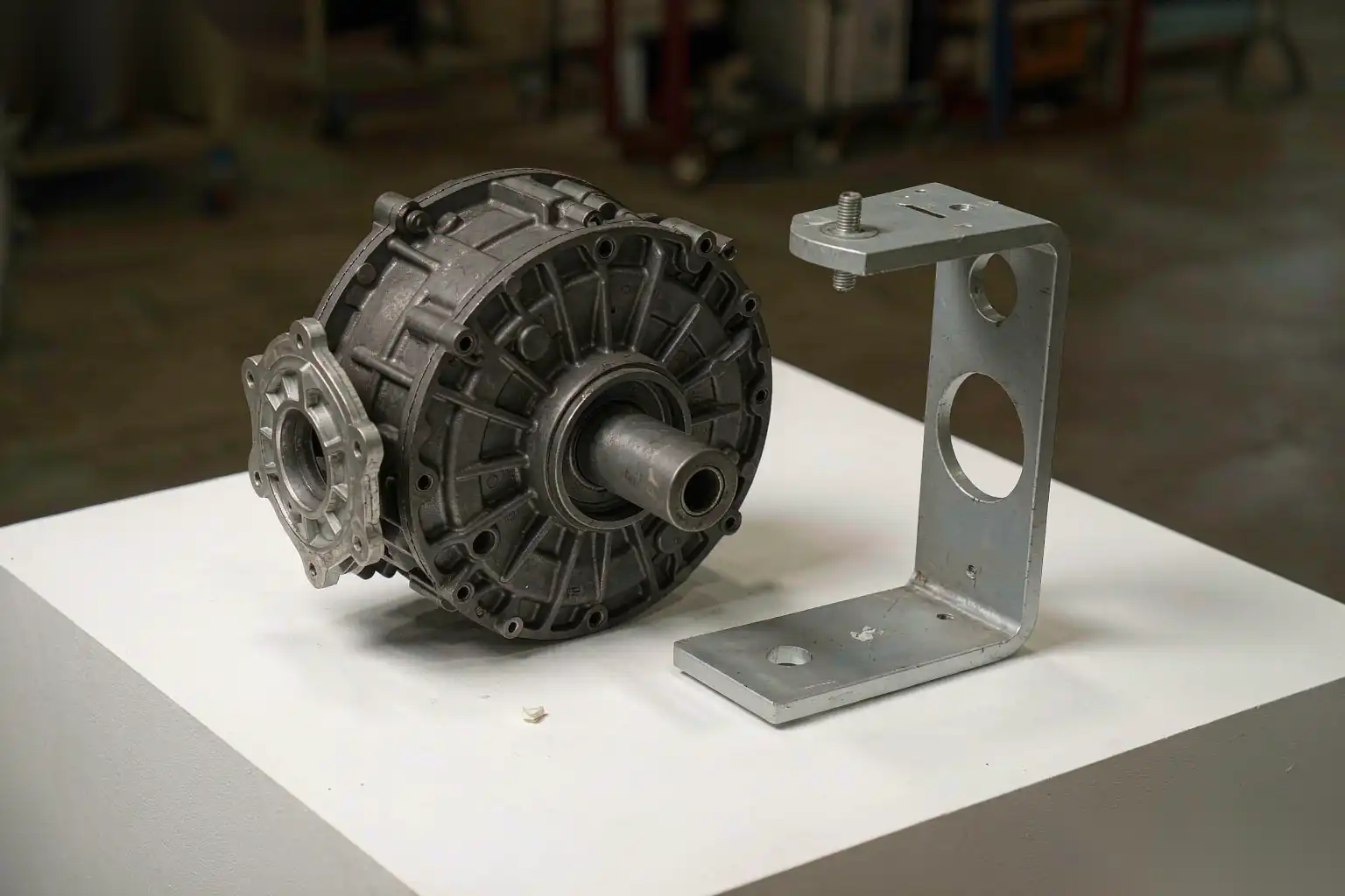
Die Casting E-Bike Components: Lightweighting and Surface Demands
E-bikes are a rare case where die casting wins on both mass and looks at the same time. A pedal-assist bike lives or dies on weight because the rider feels every gram on the climb, yet it also sits in a shop window where the customer judges the finish like a consumer product. That double demand, structural lightness plus showroom surface, is exactly where aluminum die casting earns its place across hubs, brackets, motor housings and frame hardware. The engineering work is in hitting a wall that is thin enough to be light but stiff enough not to flex, and then finishing it so the visible face passes a buyer’s eye rather than an engineer’s tolerance. This article covers which e-bike parts belong in die casting, the wall and stiffness trade-offs, the surface expectations, and how we build outdoor corrosion protection and robotic polishing into one line.
Which e-bike parts suit die casting
Not every e-bike component should be die cast. The decision follows the same logic as any structural aluminum part: does it have enough volume, enough complexity, and a shape that rewards a tool rather than a billet.
- Motor housings: the ideal die-cast part. A hub or mid-drive motor shell is a hollow, ribbed, boss-heavy enclosure made in 20,000 to 500,000 units a year, where machining a solid block would waste 70 to 80 percent of the metal.
- Battery tray and mounting brackets: good candidates where stiffness and repeatability matter more than absolute strength, and where the part can carry integrated clips and guides.
- Stem, handlebar and seat-post clamps: strong candidates for visible cosmetic castings, often anodized or powder coated to match the frame.
- Crank arms and load-bearing frame joints: use caution. These see fatigue and impact loads where die-cast porosity and the alloy’s lower elongation (around 1 to 3 percent for ADC12) become a safety concern, so we usually forge or CNC these instead.
The quick selection rule we give customers: if the part is a housing, a bracket or a clip and the annual volume clears roughly 10,000 pieces, die casting is worth a die quote. Below that, the tooling cost dominates and CNC or a simpler process wins.
Wall thickness versus stiffness trade-offs
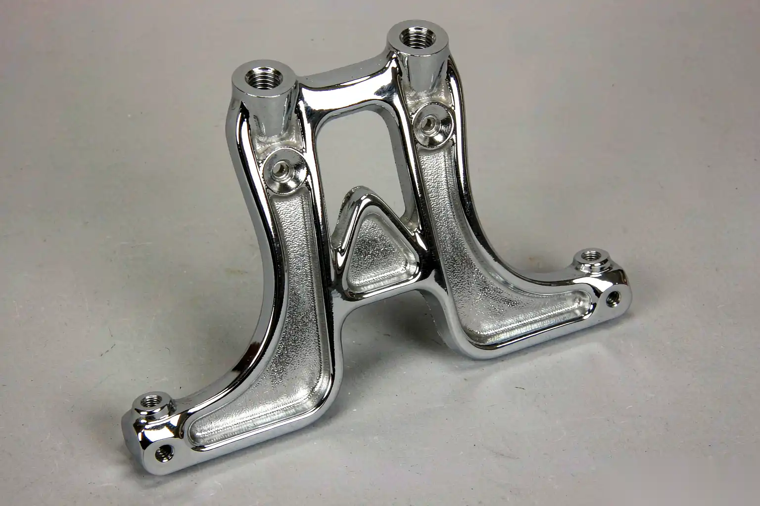
E-bike parts push thin walls harder than most casting jobs because weight is the product. But thin walls on a die casting are not free; they trade away stiffness and, if taken too far, fill quality.
| Wall section | Typical die-cast thickness | Stiffness behavior | Risk if too thin |
|---|---|---|---|
| Motor housing shell | 2.0 to 3.0 mm | Adequate with ribs | Cold shut, miss at fill end |
| Battery bracket | 2.5 to 3.5 mm | Good with gussets | Rattle and resonance |
| Visible clamp body | 3.0 to 4.0 mm | High, reads solid | None structural, just heavier |
| Mounting flange | 4.0 to 6.0 mm | Local rigidity for bolts | None, just added mass |
The design technique that lets us go thin without flimsy is ribbing. A 2.5 mm wall with a 1.5 mm tall rib every 25 to 40 mm bends far less than a bare 3.0 mm wall, at lower total mass, because stiffness scales with the cube of section depth while mass scales linearly. We aim rib heights of 0.6 to 1.0 times the wall thickness and keep rib drafts at 1 to 2 degrees so the part ejects cleanly.
Wall thickness also sets the fill window. Below about 1.5 mm the metal freezes before the cavity fills unless injection is fast and the die is hot, and fast injection folds air that shows as porosity on a later polished face. We hold a floor of 2.0 mm on visible structural walls for e-bike parts and use the aluminum die casting thin wall design guide methods of balanced gating and die-temperature control to push thin sections without sacrificing soundness. For a mid-drive motor shell we typically run the die at 180 to 220 degrees Celsius with a fill time under 40 milliseconds to reach 2.0 mm ribs without cold shut.
Stiffness is verified, not assumed. We run a simple beam or modal check on the first article: clamp the part as it mounts and measure deflection under a representative load, often 50 to 150 N for a bracket, and compare to the target. If it rings or flexes more than the limit, we add a rib or thicken a local boss rather than thickening the whole wall, which preserves the weight win.
Cosmetic expectations for consumer products
An e-bike is sold in a showroom, so the casting surface is judged like a phone case, not like a pump. The tolerance for a blemish is tiny even though the part is structural.
- Visible faces: no flow line deeper than 0.05 mm, no cold shut, no ejector mark over 0.08 mm, target Ra 0.8 to 1.6 micrometer after finish.
- Hidden structural faces: flow lines up to 0.15 mm acceptable, sink marks controlled below 0.2 mm on non-contact areas.
- Parting-line flash: removed to under 0.05 mm standout on visible edges; flash on a visible clamp is the most common consumer return we see from manual lines.
The way to hold this is to design the part so the gate, vent and ejectors land on hidden faces, and to bake the texture into the die. A vapor-honed or bead-blasted cavity gives a uniform matte that reads as a deliberate design finish; a random hand-polished repair reads as damage. For e-bike parts the die texture investment pays back immediately because it removes a whole class of cosmetic arguments at incoming inspection.
Color matching is a real requirement. A clamp anodized to the wrong shade next to a painted frame is a visible miss. We lock the anodize or powder spec against a master sample and verify it on the first article and on a per-lot audit, because batch-to-batch shade drift is normal in both processes and only catches the eye on a consumer product.
Corrosion protection for outdoor use
An e-bike lives outside. Rain, road salt, sweat and chain lube all attack aluminum, and a battery bracket that corrodes through is a safety and warranty problem, not just a cosmetic one. The finish is the protection.
| Environment | Threat | Finish approach | Expected behavior |
|---|---|---|---|
| Dry indoor storage | Minimal | Clear anodize | Adequate, mostly cosmetic |
| Daily outdoor, no salt | UV, rain, grime | Sealed anodize or thin powder | 5 to 10 year appearance life |
| Coastal or winter road salt | Chloride pitting | 60 to 80 micrometer powder over chromate-free conversion | Best resistance, longer life |
| Sweat and handle contact | Localized corrosion | Sealed anodize on gripped parts | Needs periodic clean |
The order of operations matters for corrosion more than the coating choice. We clean and de-oxide the as-cast surface, apply a chromate-free conversion layer for adhesion, then coat. Skipping the conversion layer to save a step is the usual reason a powder coat peels at a sharp edge after one season. Edges are the weak point: a coating thinner than 40 micrometer at a break edge pits first, so we specify a minimum edge radius of 0.5 mm and verify coating thickness at the edge with a gauge, not just on the flat.
For the corrosion route we lean on the die cast aluminum powder coating guide for choosing between anodize and powder by environment. On a salt-exposed market we default to powder, because it bridges edges and minor substrate defects better than a thin anodize and survives the abuse a bike takes.
A detail that saves warranty claims: we insist on draining any blind pocket in the design so water does not sit against a thin coated wall. A trapped pool under a battery tray accelerates crevice corrosion no coating fully stops. A 3 to 5 mm drain or a vented pocket is a design fix, not a finishing fix.
Robotic polishing for visible surfaces
Consumer e-bike parts are where robotic polishing earns its keep, because the buyer sees the surface and the volume pays for the cell. A force-controlled polishing robot holds the same pressure on the same face every cycle, so the class A surface looks identical across 50,000 clamps, which a hand operator cannot promise at hour eight of a shift.
Our e-bike polishing cell runs:
- Gate and flash trim at the die or by saw, with the gate on a hidden face by design.
- CNC machining of mounting faces, clearance holes and thread bosses, holding plus or minus 0.1 mm on features under 100 mm.
- Robotic deburring with a force-controlled floating spindle at 15 to 40 N, breaking edges to a 0.5 to 1.0 mm radius depending on surface class.
- Robotic polishing or buffing on visible faces, with automatic compound application so cut rate stays constant across the shift.
- Clean, inspect and pass to the coating line.
The force window is the control that protects a thin visible wall. If the robot presses too hard on a 2.5 mm clamp face it can glaze or gouge the surface in a way a person would avoid by feel. We set the window from the first-article approval and alarm if spindle load leaves it, because a load drift usually means a worn belt or a clog, both of which change the finish. Tool life is logged against part count and belts are changed on a schedule, not when they look dull, because a tired belt cuts inconsistently and that shows on the visible face.
For a two-tone look, common on flagship e-bikes, we mask before coating so a polished raw-aluminum accent sits next to a colored face. Masking is done at the cell with fixtures, not by hand taping, so the mask line is straight and repeatable. That repeatability is the difference between a premium look and a homemade one.
Acceptance and the high-mix reality
E-bike makers run many models with modest annual volumes each, so the finishing cell has to be flexible, not dedicated. We build the cell around quick-change fixtures and stored programs so a clamp, a bracket and a motor shell can run on the same robot by swapping the fixture and loading the program, typically under 15 minutes including air and I/O confirmation.
| Check | Method | Frequency | Accept |
|---|---|---|---|
| Cosmetic class A | Visual under 1000 lux vs master | Every part at cell, audit 5 per lot | No flow line deeper than 0.05 mm |
| Edge radius | Profile gauge | 2 per shift | 0.5 to 1.0 mm as specified |
| Coating thickness | Gauge on flat and edge | 1 per lot of 200 | 60 to 80 micrometer powder, 10 to 25 anodize |
| Salt spray (qualification) | 480 to 1000 h neutral salt | Per finish change | No creep beyond 2 mm from scribe |
| Dimensional | CMM on datums | 3 per die service | Plus or minus 0.1 mm features |
Salt spray is a qualification test, not a per-part test, but we run it whenever the coating supplier or the alloy batch changes, because that is when creep shows up. A scribe-through test at 480 to 1000 hours neutral salt tells us whether the edge protection is real. We have seen a coating that looked fine on the flat fail at the edge in under 300 hours, which is exactly the field failure a bike sees in a coastal city.
The wider context for these parts is in our aluminum die casting applications by industry guide, which shows how the same cells serve adjacent light-vehicle and mobility programs. For e-bike makers the takeaway is that die casting is not just cheaper per part, it is the only way to get a light, stiff, showroom-grade aluminum component at volume without machining away most of the metal.
Die casting e-bike components is a weight-and-beauty problem, and both are solved in the die and the finishing cell, not on the bench. A DZ Machinery robotic deburring and polishing cell built around documented force windows, fixed tool life and per-lot coating checks gives you the consistent visible surface and the outdoor corrosion protection an e-bike brand needs. If you are weighing die casting against CNC or forged parts for a new e-bike model, talk to our engineering team about your drawings and we will map the wall, stiffness and finishing steps before you cut a die.