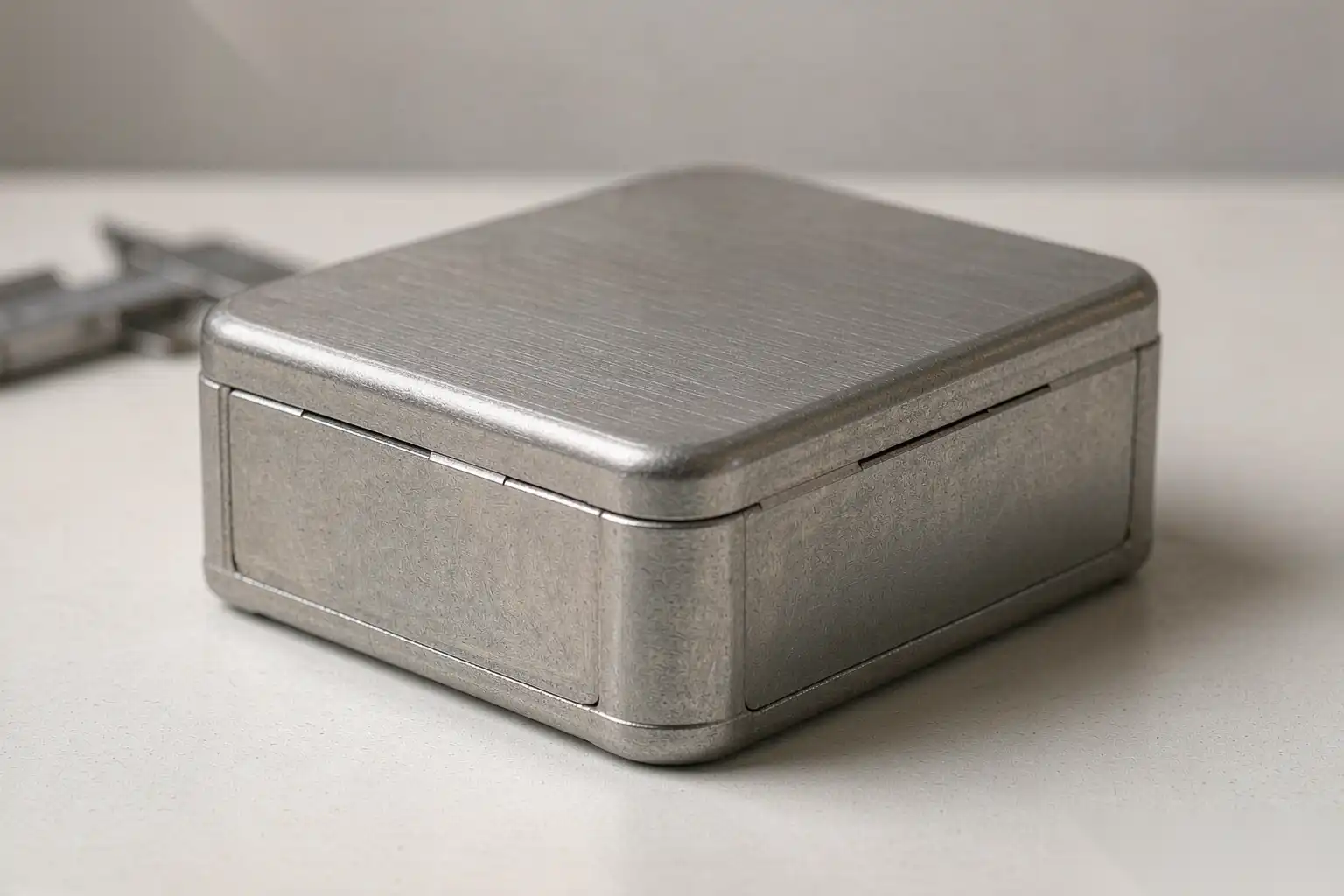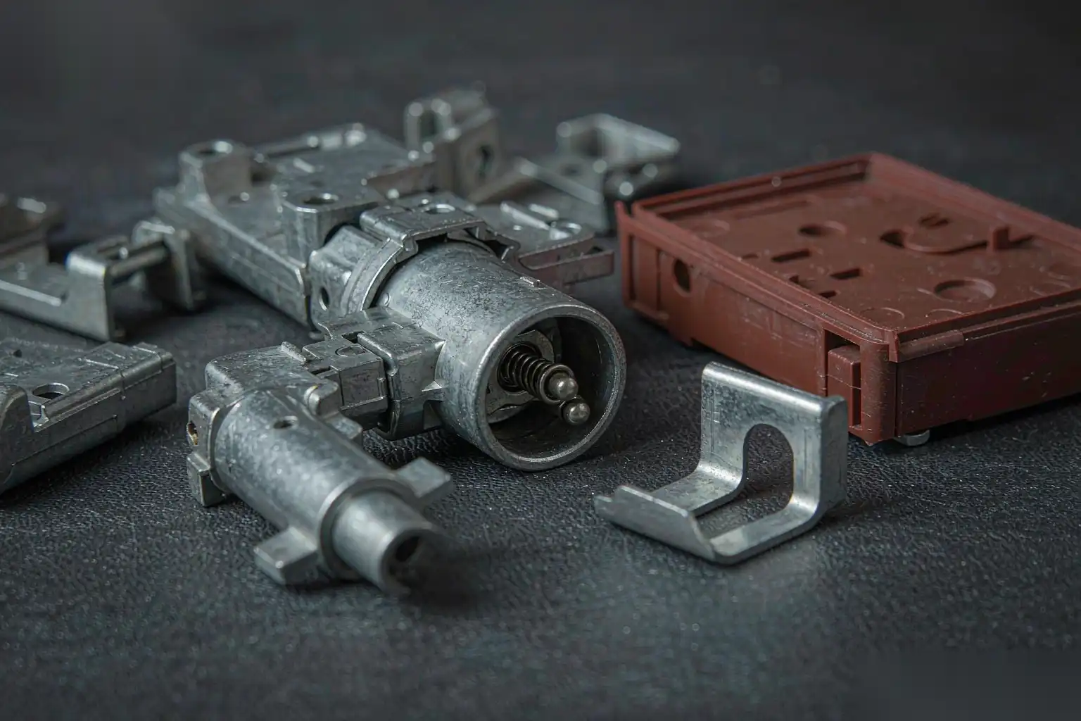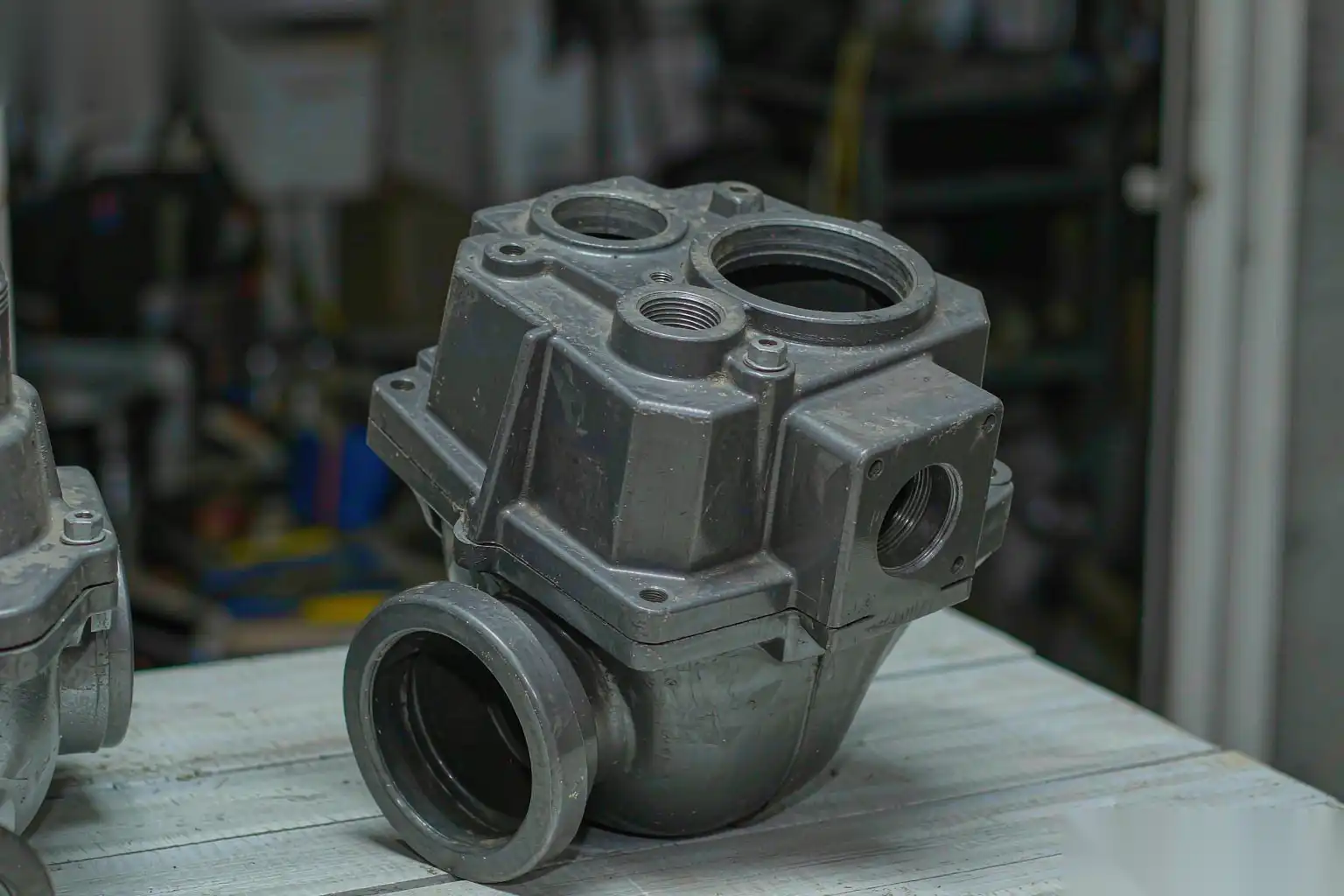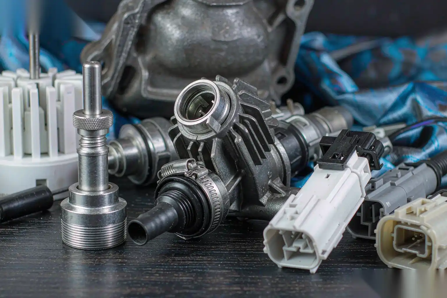
Die Casting Automotive Sensor and Connector Housings
Automotive sensor and connector housings are among the most demanding small die castings made today. The part is often the size of a thumb, it carries a sealed cavity that must keep air, water, and oil out for the life of the vehicle, it holds tight features that mate to a connector or a circuit board, and it is produced by the million with full automotive traceability. High-pressure aluminum die casting meets those requirements when porosity, dimension, and sealing are engineered from the first article. This article covers how we at DZ Smart Manufacturing approach sensor and connector housings, from vacuum casting to tolerances and automated finishing.
Why die casting for sensors and connectors
The alternative processes for a sensor body are often injection-molded plastic, machined aluminum, or a stamped and welded shell. Die casting wins on three fronts that matter in the engine bay and the chassis.
Sealing and shielding are integral. A cast aluminum housing is a continuous metal shell that gives electromagnetic shielding for the sense element and a rigid wall that a gasket or laser weld can seal against. For a wheel-speed sensor or a pressure transmitter, that sealed metal cavity protects the electronics from the brutal under-hood environment.
Precision comes from the die. Small bosses, locating pins, and connector keyways are formed in the tool rather than machined, so the part is near net shape with repeatable feature position shot to shot. For high-volume automotive, that repeatability is what lets the assembly line mate parts without sorting.
Heat and chemical resistance are inherent. Aluminum survives under-hood temperatures of 120 to 150 degrees C continuous and brief excursions higher, and it resists the oils, coolants, and road salt that destroy many plastics. For a sensor close to the exhaust or the transmission, that resistance is the reason it is cast, not molded.
The cost at volume closes the case. A machined housing from bar stock wastes material and needs multiple operations; a die-cast part is finished in one shot plus light trim and machining, which is why automotive programs with lifetimes in the millions of pieces almost always cast.
Gas-tight and liquid-tight requirements and porosity control
The defining requirement of a sensor housing is that the cavity stays sealed. Gas-tight or liquid-tight means no path through the wall, and in a die casting the only path is porosity that connects the surface to the cavity or to the outside.
Porosity in die casting comes from two sources: air trapped in the shot and gas from the die lube, and shrinkage as the metal solidifies. For a sealed housing we attack both. Vacuum assist pulls air from the cavity during fill so the metal enters with little gas to be trapped; the method and the process window are covered in our vacuum die casting guide. Shrinkage porosity is controlled by gating and cooling so the part solidifies toward the gate and feeds properly, with no isolated hot pools.
Acceptance is by test, not by assumption. We qualify a housing with a helium leak test or a pressure-decay test on the sealed cavity, often targeting a leak rate in the range of 1e-4 to 1e-3 millibar per liter per second depending on the application, and we section and X-ray early articles to confirm there is no connected porosity through the wall. A part that passes X-ray but fails leak is a sign the test method or the wall thickness needs revision.
Wall thickness is the porosity lever. Thin, uniform walls freeze fast and trap less gas; thick sections are where shrinkage voids hide. We keep the sealed wall in the 1.5 to 3.0 mm band and avoid local thickenings at the seal face, because a void there is exactly the leak path.
The table below maps requirement to control.
| Requirement | Failure mode | Control |
|---|---|---|
| Gas-tight cavity | Trapped air porosity | Vacuum assist, balanced gate |
| Liquid-tight seal face | Shrinkage void at wall | Controlled solidification, cooling |
| Long-term seal | Creep at gasket | Stable alloy, correct boss design |
| No leak path | Connected porosity | X-ray and leak test at FAI |
Thin walls and minimum features
Sensor housings push the lower edge of what die casting can hold. The connector keyway, the O-ring groove, and the locating dowel are small features that must be present and correct every shot.
Minimum wall for aluminum HPDC on a small housing sits around 1.2 to 1.5 mm for short flows and 1.5 to 2.0 mm for longer ones. Below that, fill becomes unreliable at the far features. We use high fill velocity, often 30 to 60 meters per second at the gate, and a generous overflow and vent layout so the last metal into the tool is clean and the features fill.
Minimum feature size follows the alloy and the draft. A rib or a key as small as 0.5 to 1.0 mm can be cast if it has draft and is not at the end of a long thin fill path. Core pins for small holes are limited by pin strength; a 1.0 mm core pin in a hot die is fragile, so we prefer to machine critical small holes after casting and only core what the process can hold reliably.
Draft is non-negotiable on small features. We hold 1 to 2 degrees on internal walls and 2 to 3 degrees on external where the part allows, because a feature without draft either sticks or needs a fragile, short-lived core. The trade is a slightly larger feature than the ideal, which we design in rather than fight after tryout.
Dimensional stability over temperature
A sensor housing lives through temperature swings that would loosen a poorly designed part. The concern is not just the metal expanding; it is the feature position and the seal staying put as the part heats and cools over the vehicle life.
Aluminum’s coefficient of thermal expansion near 21 to 23 microstrain per degree C means a 30 mm feature span moves roughly 0.02 mm over a 30 degree C swing. For most connector features that is acceptable if the mating part is also aluminum or is designed with clearance, but against a plastic or ceramic mate it must be accounted for in the tolerance stack.
We design for stability by locating critical features relative to a stable datum and by keeping the wall around them uniform so they move together rather than warp. A boss that is thick on one side and thin on the other will tilt as it heats, shifting the screw or the pin; uniform walls keep the feature where it was cut.
The tolerance strategy is in our aluminum die casting tolerances guide. For sensor housings we typically hold critical features to plus or minus 0.05 to 0.1 mm by machining them after casting, and hold the cast envelope to plus or minus 0.1 to 0.2 mm per 25 mm, then verify the thermal shift by measuring parts at room temperature and at an elevated soak.
Insert molding and overmolding interfaces
Many sensor housings are not pure castings; they carry inserts or are overmolded, and the interface must be designed so the cast part does the structural job while the insert or plastic does the sealing or the mating.
Inserts cast in place include terminals, pressed bushings, and sometimes the sensor element carrier. The die must locate the insert repeatably and the aluminum must not displace or short it; we design the insert with a mechanical lock, such as knurls or a flange, so the aluminum grips it through thermal cycling rather than relying on a friction fit that relaxes.
Overmolding interfaces are where the cast housing meets a molded gasket or a connector shell. The cast surface there needs a controlled texture or an undercut so the molded material bonds or mechanically locks; a smooth as-cast face will let the overmold peel under heat. We specify the interface geometry at DFM and verify the bond with a pull or a peel check on first articles.
Hermetic versus resilient seal is the design choice. A laser-welded or brazed lid gives a true hermetic seal for the sense cavity; a molded gasket gives a serviceable, resilient seal that tolerates the thermal movement better. We pick based on the failure mode the application cannot accept, and the casting is designed to support whichever is chosen.
Automotive traceability and PPAP
An automotive housing is not shipped on a pallet and forgotten; it carries a traceability chain from the melt to the box, and it passes a Production Part Approval Process before volume.
Traceability starts at the alloy. Each lot of aluminum is logged by heat number and the casting lot is tied to it, so a field failure can be traced to the melt and the machine and the shift. The die casting cell records shot parameters, cycle time, and any alarm per cavity or per part where the system supports it, building the data set PPAP and ongoing control plans require.
PPAP requires documented capability. We run a measurement study on the critical features, confirm the process is capable at the required Cpk, and submit the first article inspection report, the process flow, the control plan, and the capability studies. The first article method for castings is detailed in our quality references, and we treat the FAI as the gate that proves the die and the process before a single production piece ships.
Control plans then hold the line. Key characteristics, leak rate, critical dimensions, and process windows are monitored, and any drift triggers containment. The point is that automotive volume magnifies any defect, so the system catches it at the cell, not at the OEM.
Automated finishing for consistent quality
Sensor housings are small, high-volume, and unforgiving on defects, so manual finishing cannot hold the spec. Automated deburring and inspection are how the part stays consistent across millions of pieces.
A DZ robotic cell deburrs the parting line and gate with a compliant spindle and a small carbide or abrasive tool, breaking edges to a safe, consistent radius without touching the seal face or the connector features. Because the parts are small and the features are close, the cell uses precision fixturing and vision or probe confirmation so the tool never marks a critical surface.
Trimming the gate and any flash is often done at the cell or at a trim press before it, and the part then moves to wash and dry so the finishing and the leak-test stations see a clean component. Consistency matters because a leftover fin at the seal groove is exactly the kind of defect that passes a visual check and fails a leak test later.
Inspection is built in. We favor in-line leak testing and a gauge or vision check on the critical features so a drift in dimension or a porosity leak is caught at rate, not at audit. The data feeds the traceability record per part or per lot. The yield and scrap discipline behind this is in our die casting yield and scrap reduction guide.
Cycle time on a small housing deburr is often 8 to 20 seconds, which matches the casting rate on a multi-cavity die, so the finishing cell does not bottleneck the line. Fixtures locate on stable datum and keep the seal face clear of clamps, and tool wear is tracked so the edge break stays in spec across the run.
Design checklist before tooling a sensor housing
We close a sensor housing review with a short list to avoid a costly die revision:
- Confirm the seal requirement: gas-tight, liquid-tight, or hermetic, and set the leak rate target up front.
- Decide vacuum assist and the gate and cooling layout to keep porosity out of the wall.
- Hold the sealed wall in the 1.5 to 3.0 mm band and avoid thick sections at the seal.
- Cast only features the process can hold; machine critical small holes and tight features after casting.
- Design inserts and overmold interfaces with mechanical lock and a defined cast surface.
- Plan the tolerance stack across the temperature swing and verify with a hot measurement.
- Build the traceability and PPAP data set from the first shot, with in-line leak and dimension checks.
Die casting automotive sensor and connector housings is a precision game: keep porosity out of the sealed wall, hold the small features by machining what the process cannot, and verify sealing and dimension at rate with full traceability. DZ Machinery builds the robotic deburring, grinding, and polishing cells and the process monitoring that turn raw aluminum sensor housings into consistent, leak-tight production parts; if you are developing an automotive sensor or connector housing and want to review part drawings, porosity strategy, and a finishing cell layout, our engineering team can run a feasibility and cycle-time estimate on your components.