Powder Coating Die Cast Aluminum: Pretreatment, Cure Windows and the Defects That Come From the Casting
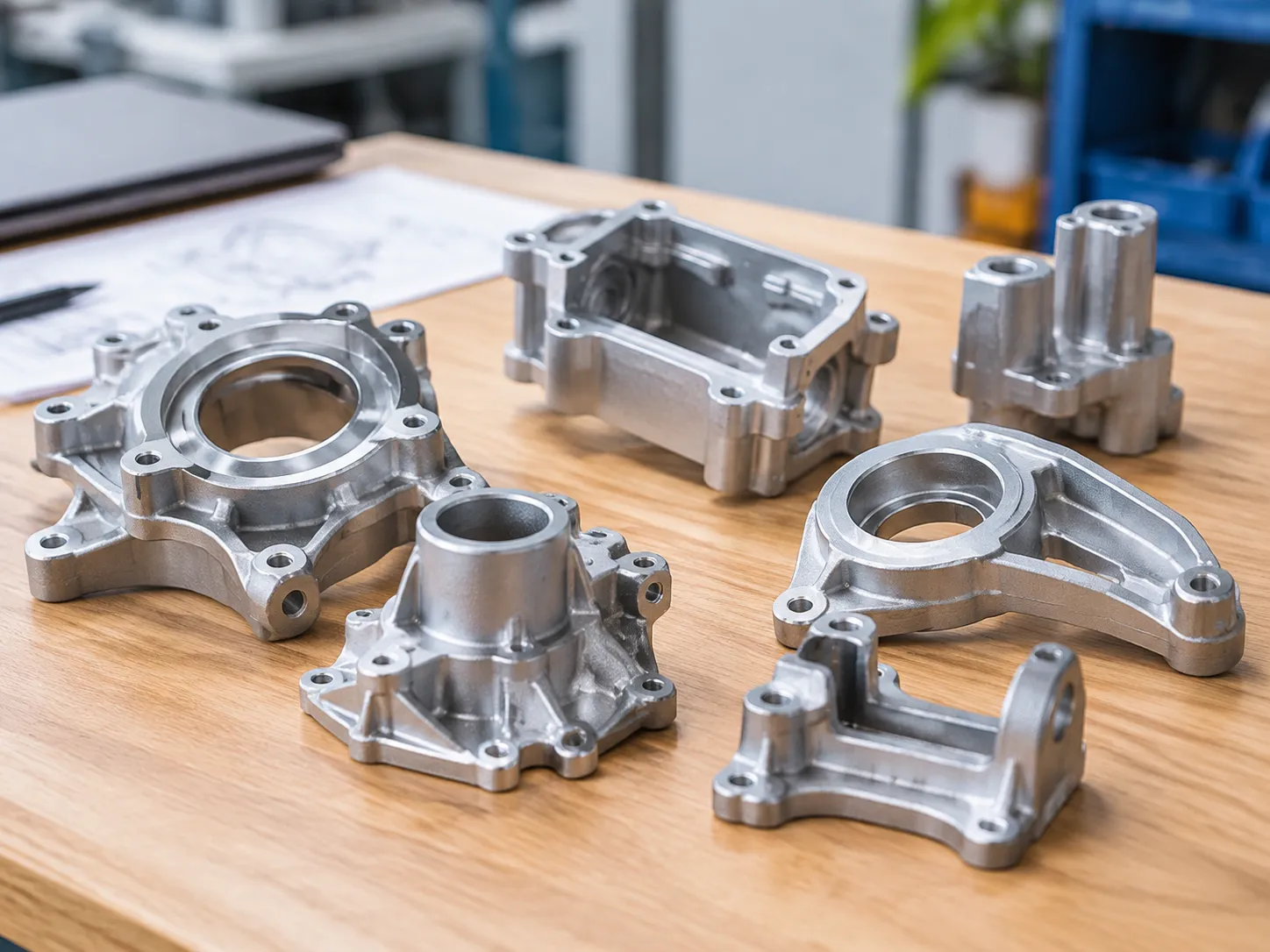
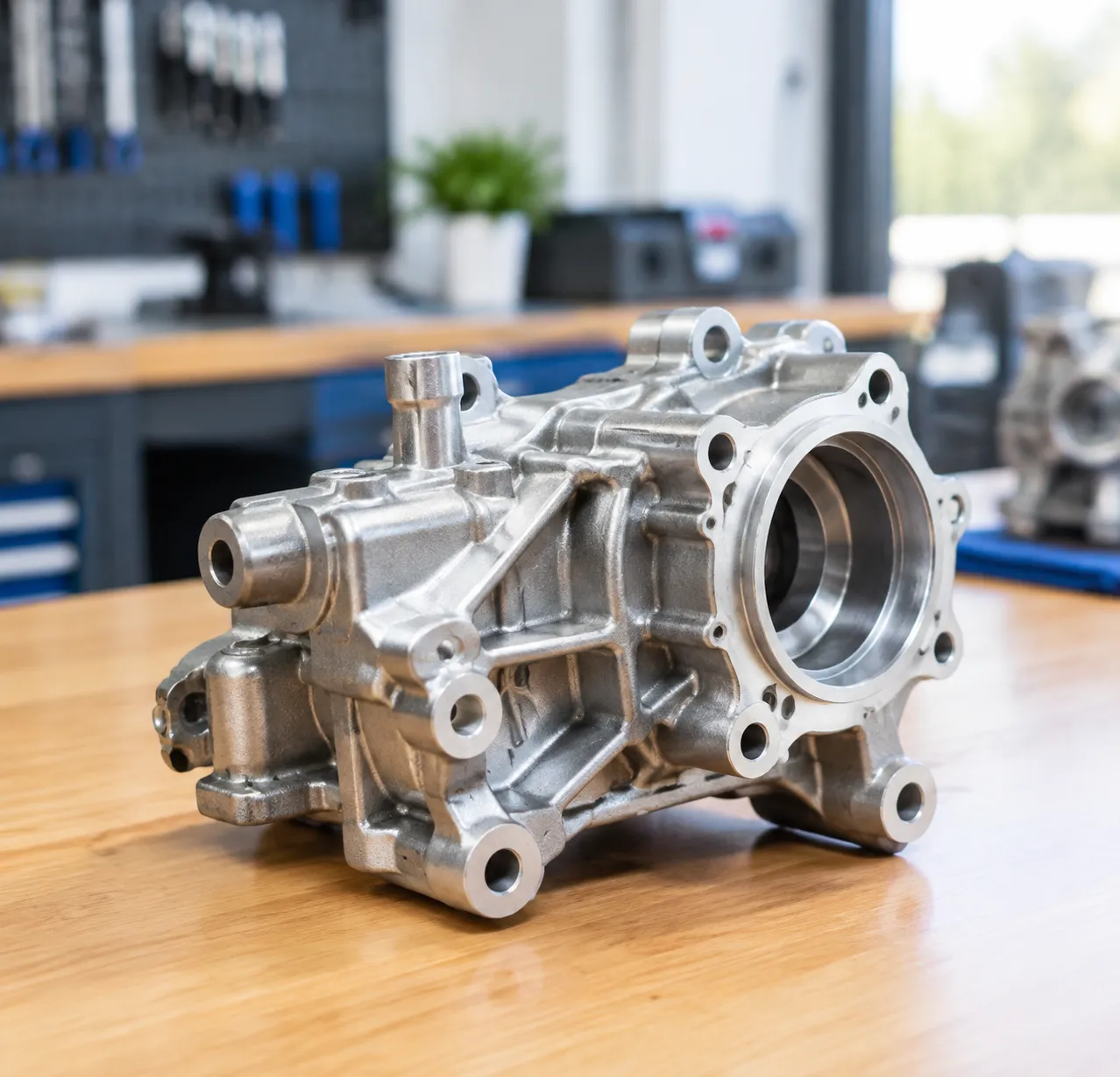
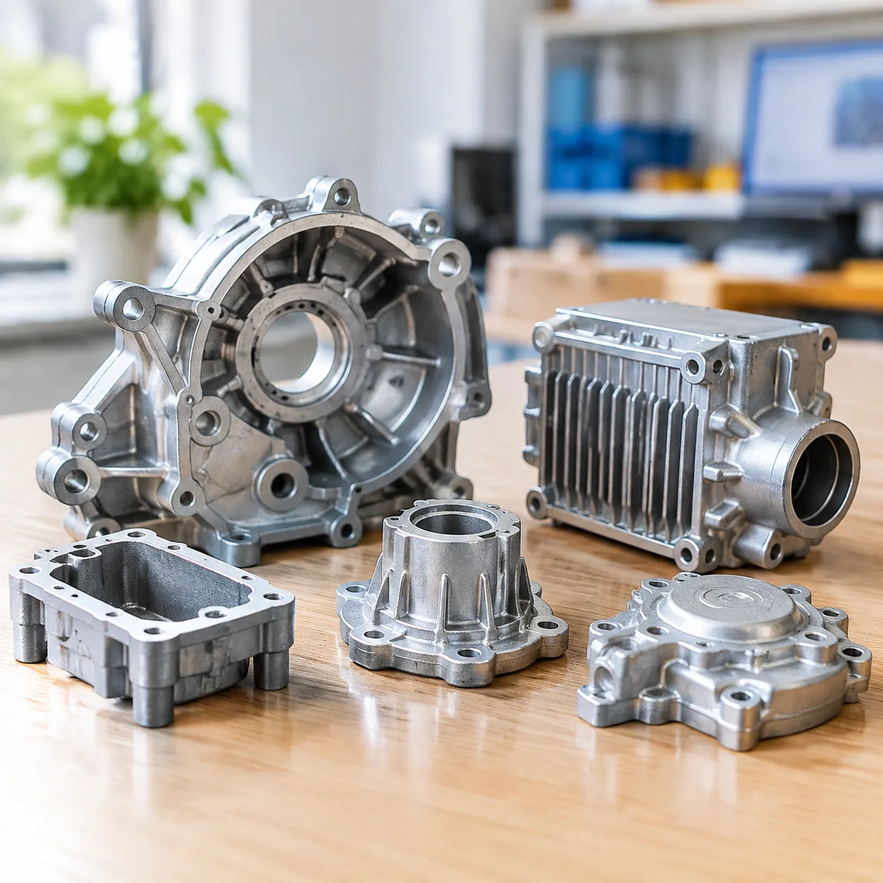
Powder coating is the default finish for die cast aluminum enclosures, brackets, housings and hardware because it is thick, tough, cheap per square metre and solvent-free. It is also the finish that most reliably exposes everything the casting did wrong. Unlike paint, powder film is applied dry and then melted, which means there is no solvent to carry resin into a scratch, and no way for entrapped gas to escape once the film gels.
This article goes through the whole route: why die castings outgas and blister, the pretreatment chain with real setpoints, the outgassing bake, how to choose a resin system, the application variables that govern Faraday cages and recess coverage, what causes orange peel and holidays, how to test adhesion and define acceptance, and why the mechanical preparation stage before the booth decides most of the result.
Why Die Castings Outgas and Blister
A high pressure die casting contains entrapped gas. Even a well-run cold chamber shot holds 2 to 6 percent porosity by volume in thick sections, distributed as discrete spherical pores from 20 to 300 micrometres across, plus shrinkage porosity at hot spots. Vacuum-assisted casting typically brings that down to 1 to 2 percent, and squeeze or low pressure casting lower still.
The problem is what happens to that gas during cure. A pore sitting at ambient is at roughly 298 K. In a 200 degree Celsius cure oven the metal reaches 473 K. By the ideal gas relationship that is a volume increase of about 1.6 times, before considering the vapour pressure of any moisture, die lubricant residue or machining coolant that found its way into the pore. Meanwhile the powder film has melted at around 90 to 110 degrees Celsius and gelled, so the expanding gas has no path out except through a film whose viscosity is rising by the second.
The result is a pinhole, a crater or a blister, and three variables decide whether you get one:
- Pore depth. Pores within roughly 0.3 to 0.5 mm of the surface are the dangerous ones. Deeper pores are usually sealed by the casting skin and do not connect.
- Pore connectivity. A closed pore 0.5 mm below the surface does nothing. The same pore connected to the surface by a machining cut, a grinding smear or a micro-shrinkage channel will outgas.
- Cure temperature. Lower cure temperature means less expansion. Moving from a 200 degree cure to a 160 degree low-cure powder reduces the gas volume increase from about 1.6 times to about 1.45 times, which is often enough to close the difference between acceptable and rejectable on a marginal casting.
The practical implication is that powder coating cannot be specified without a porosity specification behind it. If the drawing does not say what porosity is acceptable near a coated surface, then the coater is absorbing a risk that belongs to the foundry. The mechanics of where that porosity comes from are covered in aluminum die casting porosity: causes and solutions.
The Pretreatment Chain and Its Setpoints

Most powder failures on die castings are pretreatment failures that only become visible after cure. This is the chain we specify, with the parameters that have to be logged.
| Stage | Chemistry | Temperature | Time | Control parameter |
|---|---|---|---|---|
| 1. Clean | Alkaline soak or spray, pH 10 to 12 | 50 to 65 degrees Celsius | 3 to 6 min | Free alkalinity 8 to 15 points; water break-free test after rinse |
| 2. Rinse | Tap water, overflowing | Ambient | 60 to 90 s | Conductivity rise under 100 microsiemens per cm over feed |
| 3. Etch or deoxidize | Alkaline etch, or fluoride/nitric or ferric sulfate deoxidizer | 25 to 45 degrees Celsius | 30 to 120 s | Metal removal 1 to 3 micrometres, or 0.5 to 1.5 g per square metre |
| 4. Rinse | Tap water, counterflow | Ambient | 60 to 90 s | pH 6 to 8 |
| 5. Conversion coating | Zirconium or titanium based, chrome-free | 25 to 40 degrees Celsius | 30 to 90 s | Bath pH 3.8 to 5.0; coating weight 20 to 80 mg per square metre |
| 6. Final rinse | Deionised or RO water | Ambient | 30 to 60 s | Conductivity under 50 microsiemens per cm, target under 30 |
| 7. Dry-off | Convection oven, air knife | 90 to 120 degrees Celsius | 5 to 10 min | No water in recesses; part surface dry on exit |
| 8. Outgassing bake | Convection oven | 200 to 215 degrees Celsius metal temperature | 20 to 30 min | Metal temperature, not air temperature, is the setpoint |
| 9. Cool | Ambient or forced | Below 45 degrees Celsius before coating | — | Under 35 degrees for corona guns, tribo tolerates warmer |
Four comments on that chain, because these are the stages that get skipped:
- Cleaning is the stage that removes die lubricant. HPDC parts carry a release agent film that no amount of powder will bond to. If the water break-free test fails after stage 2, stop the line; everything downstream is wasted.
- Deoxidizing removes the smut that etching leaves. Aluminium with 9 percent silicon leaves a grey silicon smut after alkaline etch. If it is not removed, you get a conversion coating sitting on loose silicon, and adhesion that passes the cross-cut test and fails in humidity.
- The final DI rinse determines salt spray performance more than the conversion bath does. Dissolved solids left on the surface become osmotic cells under the film. Going from 150 to 30 microsiemens per cm on the final rinse is usually worth several hundred hours of salt spray.
- The outgassing bake is not optional on die castings. Twenty to thirty minutes at cure temperature plus 10 degrees, before coating, typically reduces pinhole rejects by 60 to 80 percent on a casting with marginal porosity. It is a cheap stage and it pays for itself in weeks.
Choosing the Powder Resin
| Resin system | Cure window (metal temperature) | Gloss at 60 degrees | Strengths | Limits |
|---|---|---|---|---|
| Epoxy | 160 to 180 degrees Celsius, 10 to 15 min | 85 to 95 | Best adhesion, chemical and salt resistance; lowest cure temperature | Chalks in UV, indoor only |
| Epoxy-polyester hybrid | 180 degrees Celsius, 10 to 15 min | 70 to 90 | Balance of properties and cost; forgiving cure | Limited exterior durability, 6 to 12 months UV |
| Polyester TGIC | 200 degrees Celsius, 10 min, or 180 degrees for 15 to 20 min | 80 to 95 | Exterior durable; QUV-B 1000 h gloss retention over 50 percent | Regulatory restrictions in some markets |
| Polyester TGIC-free, HAA cure | 180 to 200 degrees Celsius, 10 to 15 min | 75 to 90 | Exterior durable, no TGIC | Yellowing on overbake; outgassing pinholes in films over 120 micrometres |
| Polyurethane | 180 to 200 degrees Celsius, 10 to 15 min | 85 to 95 | Very smooth flow, good chemical resistance | Higher cost; sensitive to overbake haze |
| Superdurable polyester | 200 degrees Celsius, 10 min | 70 to 90 | QUV-B 3000 h plus, Florida exposure 3 to 5 years | Premium price |
| Fluoropolymer, FEVE | 200 to 220 degrees Celsius, 15 to 20 min | 50 to 85 | 10 to 20 year gloss retention | Highest cost, needs primer, restricted colour range |
Most die cast hardware lands on either a hybrid for indoor products or a TGIC-free polyester for anything that sees daylight. Where the casting is porous and the geometry is complex, an epoxy-based system cured at 160 to 170 degrees is often the more forgiving choice despite the UV limitation, purely because of the lower outgassing driving force.
Target film build is 70 to 90 micrometres. Below 50 micrometres you fight orange peel and holidays; above 120 micrometres you risk mud cracking on sharp corners, back-ionization craters, and a material cost increase that is linear with thickness.
Application Variables: Faraday Cages, Recesses and Edge Coverage
A corona gun charges particles to 30 to 80 kV at 10 to 30 microamps, and the charged particles follow field lines. Field lines concentrate at external corners and do not enter recesses, which produces two classic problems at once.
- Faraday cage areas. Inside corners, channels and boxes get little or no powder. Practical fixes, in order of effectiveness: reduce gun voltage to 20 to 30 kV, reduce powder flow to 100 to 150 grams per minute, move the gun further back to 250 to 300 mm so the cloud has time to drift into the recess, use an extended or angled nozzle, and if the recess is the dominant feature, apply with a tribo gun in that zone.
- Recess geometry. Coverage falls off sharply when recess depth exceeds about three times the opening width. A 15 mm wide channel more than 45 mm deep will not coat reliably with a corona gun. Design the casting so decorative recesses stay below a 2:1 depth-to-width ratio, or accept a manual touch-up station.
- Back ionization. Push film thickness above roughly 100 to 120 micrometres at high voltage and the accumulated charge breaks down through the film, leaving craters or a matte, orange-peel surface. Reduce voltage rather than adding more powder.
- Grounding. Part-to-earth resistance must be under 1 megohm, checked at the hanger contact point and logged. Poor grounding gives thin film, poor wrap and unpredictable transfer efficiency.
- Edge coverage. When the powder melts, surface tension pulls the liquid film away from sharp edges. A 90 degree edge typically retains only 50 to 70 percent of the nominal film thickness, which is why edge corrosion starts first on coated castings. The fix is mechanical: break the edge to a radius of at least 0.5 mm, preferably 1.0 mm. Chemistry and gun settings cannot compensate for a zero-radius edge.
Defects, Root Causes and Corrective Actions
| Defect | Appearance | Root cause | First corrective action |
|---|---|---|---|
| Pinholes and blisters | Small craters or domes, concentrated over thick sections | Outgassing from subsurface porosity | Extend outgassing bake 10 min; drop cure temperature 20 degrees; specify casting porosity limit |
| Orange peel | Wavy, orange-skin texture | Film too thin, coarse particle size, slow oven ramp | Raise film to 70 to 90 micrometres; check reclaim ratio and particle size distribution |
| Picture framing | Heavy build at edges, thin in recesses | Faraday cage effect | Drop voltage to 20 to 30 kV, increase gun distance, use tribo in the zone |
| Craters | Small round depressions with a raised rim | Back ionization, or oil and silicone contamination | Reduce voltage and film build; audit compressed air and conveyor lubricant |
| Poor adhesion | Film peels in tape test | Inadequate cleaning, exhausted conversion bath, dirty final rinse | Rebuild cleaner, check conversion coating weight, lower final rinse conductivity |
| Holidays | Bare metal in isolated spots | Poor grounding, insufficient film, part geometry shadowing | Check earth resistance under 1 megohm; raise film build; add a touch-up gun |
| Colour drift | Batch to batch shade difference | Reclaim ratio drift, oven temperature spread | Cap reclaim at 20 to 30 percent of feed; tighten oven setpoint to plus or minus 5 degrees |
| Grit show-through | Substrate texture visible through film | Substrate too rough for the film build | Reduce as-ground Ra; increase film build; use a smoother flow grade |
Cure, Testing and Acceptance
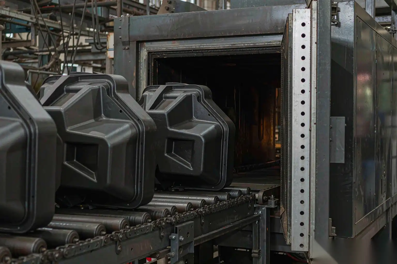
Cure is specified as metal temperature for a defined dwell, not as oven air temperature or conveyor speed alone. Powder suppliers quote cure windows such as 10 minutes at 200 degrees Celsius metal temperature, and the only way to know you achieved it is to run a data logger through the oven with thermocouples on thin and thick sections of an actual part. Typical production ovens run air at 210 to 230 degrees Celsius with a 15 to 25 minute conveyor dwell; thin die castings reach metal temperature in 4 to 8 minutes, heavy ones can take 12 to 18.
Verification methods worth writing into the control plan:
- Cure degree. MEK double rubs per ASTM D5402, with 50 double rubs without film removal as a common acceptance, or differential scanning calorimetry on a cured sample for a quantitative residual cure figure.
- Adhesion. Cross-cut per ISO 2409 or ASTM D3359, requiring classification 0 or 1. Pull-off per ISO 4624, with 5 MPa as an absolute floor and 8 to 15 MPa typical on properly pretreated aluminium.
- Thickness. Eddy current per ISO 2360 for production, cross-section per ISO 2808 for disputes, with a stated minimum at every measured point rather than an average.
- Humidity. ISO 6270-2 constant humidity test, 1000 hours, no blisters and adhesion retention above 70 percent.
- Salt spray. ISO 9227, 500 to 1000 hours depending on specification, with creep at the scribe under 1 to 2 mm.
- Impact and flexibility. ASTM D2794 impact at 40 to 160 inch-pounds depending on resin, and a conical mandrel bend per ISO 6860.
Write the specification as numbers with sampling plans and limit samples. A finish standard that says “no visible defects” is an argument waiting to happen; our overview of die casting surface finish standards shows how to convert visual requirements into measurable ones.
Mechanical Preparation Decides the Coating Result
Everything above assumes the part arrives at the booth in a defined condition. That condition is created in the deburring and grinding cell, and it is where most coating problems are actually solved.
- Flash and parting line. Powder bridges a thin flash fin rather than wrapping it, and the bridged film chips off at the first impact. Every bit of flash has to be removed, and the parting line blended over a width of at least 5 to 10 times the step height, so the transition disappears under a 80 micrometre film instead of being outlined by it.
- Edge radius. As noted, a sharp edge holds half the nominal film. Deburring should produce a consistent 0.5 to 1.0 mm radius on every external edge that matters. Hand deburring gives a radius that varies from 0 to 1.5 mm along the same edge; a robotic cell with a defined path gives the same radius on every part.
- Surface profile. Powder needs a mechanical key. Ra 0.8 to 2.5 micrometres, roughly Rz 5 to 15 micrometres, is the practical window. Smoother than Ra 0.3 micrometres reduces adhesion; rougher than Ra 6 micrometres shows through the film as texture and forces a thicker, more expensive build.
- No smearing. Burnishing metal over a pore mouth traps lubricant and moisture underneath, and that is exactly the contamination that produces craters after cure. Sharp abrasives at the correct belt speed cut; dull belts or excessive pressure smear.
- Cleanliness before the booth. Ground parts must be free of swarf, belt debris and buffing compound. On automated lines this means air blow-off at the cell exit and, ideally, coating within a defined window rather than letting ground parts sit in a humid store for a week.
This is the reason we treat the deburring cell as the first stage of the coating line rather than a separate department. DZ Machinery builds robotic deburring and grinding cells for this purpose: six-axis robots with force-controlled floating spindles, automatic belt or media changers, multi-station rotary tables, and quick-change fixtures, all inside enclosed cells with metal-dust-rated extraction. They are specified the same way the coating line is specified, by Ra, edge radius and cycle time per part, and they integrate with the sawing and CNC stages upstream and the coating booth downstream.
If your powder line is fighting pinholes, edge creep or inconsistent adhesion, the fastest diagnostic is usually not in the booth. Send us the part drawings, the alloy and a set of rejected parts, and we will run them through a preparation study: measure the as-cast condition, run the grinding sequence, and report the Ra, edge radius and cycle time we can hold, so your coating parameters have a defined substrate to work with.