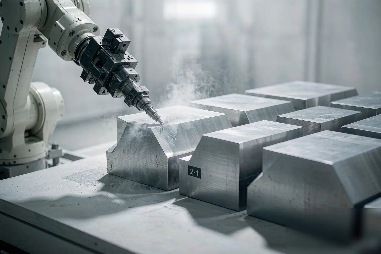
AT A GLANCE · Metal casting finishing for motorcycle parts holds tolerances that would have been machining territory a decade ago, and it works only when every link in the precision chain — robot, force control, tooling, fixture, and measurement — is budgeted and managed. One weak link consumes the whole tolerance band. How robotic finishing machines work explains the mechanics; this deep-dive follows the numbers.
Why Motorcycle Castings Demand Precision Finishing
Motorcycle parts sit in the precision middle ground. Engine covers seal against gaskets, brake components carry safety loads, and frame castings align suspension geometry. Unlike decorative hardware, these parts fail functionally when finishing drifts.
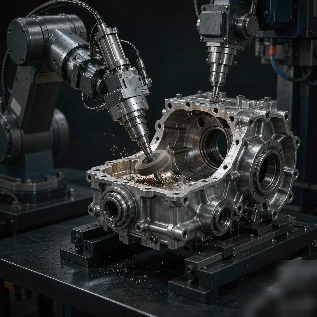
A brake caliper body needs pad-sit faces flat and parallel after grinding. A crankcase cover needs gasket rails consistent around the whole perimeter. Finish appearance matters, but the drawing’s dimensional callouts rule.
Typical requirements land at plus or minus a hundred microns on critical faces, with flatness under fifty. Achieving that on cast, not machined, surfaces is the precision challenge.
The Precision Chain, End to End
Total accuracy is a chain: robot repeatability, path following, force control, tool deflection, fixture location, part variation, thermal drift, and measurement uncertainty. Errors add, mostly as root-sum-square, and the stack must stay inside the drawing band.
The practical move is a tolerance budget. Assign each chain element an allowance, verify each, and keep twenty percent of the band in reserve. The table below shows a working budget for a hundred-micron band.
| Chain Element | Budget Allowance | Control Method |
|---|---|---|
| Robot repeatability | ±20 µm | Selection spec at purchase |
| Path following | ±15 µm | Calibrated tool centre point |
| Force control | ±25 µm | Active compliance, tuned gains |
| Tool deflection and wear | ±20 µm | Wear offsets on cycle count |
| Fixture location | ±10 µm | Hardened datums, gauged nests |
| Part casting variation | ±15 µm | Vision locate, path compensation |
| Measurement uncertainty | ±10 µm | Calibrated gauging, GR&R study |
Notice what the budget does: it turns an impossible-sounding total into seven achievable lines. When a tolerance problem appears, you audit the chain element that blew its allowance instead of blaming “the robot”.
Robot Repeatability and Path Following
Repeatability is a purchase spec, not a tuning knob. A modern mid-payload robot repeats to twenty or thirty microns at the wrist, which fits the budget above. Older arms or long-reach configurations double those numbers and need budget relief elsewhere.
Path following depends on the tool centre point calibration. A TCP set with a sphere probe holds a few microns; a taught-by-eye TCP throws away the robot’s native accuracy immediately.
Speed trades against following error. The controller rounds corners at high joint speeds, so precision passes run at reduced override — typically forty to sixty percent — while roughing passes run full speed. Splitting the program this way costs little cycle time and saves the budget.
Force Control: The Largest Single Lever
Grinding force converts directly into stock removal, and stock removal converts into dimension. A force ripple of two newtons on a typical belt moves the cut by twenty to forty microns — the entire force allowance in one fluctuation.
Passive compliance — a spring-loaded spindle mount — damps the worst spikes but cannot track surface variation. Active compliance measures force continuously and adjusts position within milliseconds, holding the band on cast geometry that varies shot to shot.
Tune the gains on your actual parts, not on the supplier’s demo block. Gains that feel crisp on a flat sample oscillate on a curved cover face. The tuning recipe is always the same: raise gain until oscillation appears, back off thirty percent.
Watch the force log like a process signal, because it is one. Rising force with constant position means tool loading; falling force means wheel wear. Either one predicts dimensional drift before the gauge sees it.
Tool Deflection, Wear, and the Offset Discipline
Every abrasive tool deflects under load and wears with use. Deflection is stable for a given force; wear is progressive. The budget handles both through offsets: a deflection offset set once per tool type, and a wear offset stepped every N cycles.
Wear offsets tied to cycle count beat offsets tied to time because cycles track actual work. A cell that ran light Monday and heavy Friday needs the cycle-based step to keep Friday’s parts in band.
Tool changes belong in the program, not in operator judgment. When the offset stack reaches its limit, the robot swaps the tool automatically and resets the offset counter. Manual judgement at 2 a.m. is where capability goes to die.
Fixtures and Casting Variation
The fixture is the datum everything else measures from. Hardened, gauged nests with positive location hold the ten-micron allowance; worn V-blocks and hope do not.
Casting variation is the input you cannot machine away, so you measure and compensate. A vision or laser locate on two datums per part takes under a second and feeds the robot a position update. The path shifts with the casting instead of fighting it.
For high-mix plants, the locate step is what makes shared fixtures viable. The same nest holds three different covers because the locate step, not the nest, resolves the final position. Aluminium casting finishing practices cover the alloy-specific side of this variation.
Thermal Effects Nobody Budgets Until They Bite
Casting finishing generates heat, heat grows structures, and growth moves the tool relative to the part. A two-degree rise on a six-hundred-millimetre steel frame grows the datum chain by about fourteen microns — most of an allowance line.
The countermeasures are unglamorous: warm-up cycles before the first measured part, consistent cycle pacing so the cell reaches steady state, and finishing-critical dimensions measured at line temperature, not on a cold morning bench.
Spindle warm-up matters most. Program a two-minute dummy-run at shift start. It costs two minutes and removes the dimensional staircase that otherwise marks every first-hour part.
Measurement and Capability Verification
The measurement allowance is small, so the gauge must be better than the tolerance. A calibrated digital height gauge or an on-machine touch probe both work; a shop-floor caliper measurement of a fifty-micron flatness does not.
Run a formal capability study at acceptance: one hundred consecutive parts, all nest positions, normal cadence. Report Cpk on each budgeted dimension. A cell is precision-capable at Cpk 1.33 or better; below 1.0 means some chain element is over budget.
Repeat the study quarterly and after any tooling or program change. Capability decays quietly through wear, and the quarterly check catches the decay while it is still an offset, not a scrap event.
Grinding consistency in metal finishing shows what stable capability looks like in production data — tight bands, no drift, boring charts. Boring is the goal.
Choosing Measurement Equipment for the Budget
The measurement allowance in the budget table is small, and the instrument earns or loses it. A height gauge on a granite surface plate holds five microns in skilled hands; a shop-floor caliper does not hold five microns on a good day.
On-machine probes close the loop fastest: measure the ground face in the fixture, and the offset updates before the next part. The trade is cycle seconds, and at motorcycle volumes those seconds are worth paying on critical faces only.
Calibrate on a schedule and record it. An uncalibrated gauge producing numbers that fit the band is worse than no gauge, because it converts doubt into false confidence.
Run a gauge study (GR&R) at acceptance. If the measurement system consumes a third of the tolerance, the cell’s real capability is two-thirds of what the Cpk study claims — and the customer’s auditor will find that before you do.
Environmental Control Beyond the Warm-Up
The warm-up cycle handles the cell’s own heat, but the building contributes its own drift. Morning sun on one side of a hall moves a long frame’s datum chain measurably by ten o’clock; shops that measure in the afternoon and grind in the morning chase a ghost.
The countermeasures are architectural more than electronic: keep the cell out of direct sun paths, measure at consistent times, and when precision really matters, enclose the gauge station with its own temperature discipline.
Coolant temperature belongs in the same conversation. Mist systems that draw from a tank sitting on a cold floor deliver varying viscosity through a shift, and varying viscosity varies the cut. Tank temperature is a process parameter — log it.
Compressed air dryness closes the list. Wet air corrodes fixture datums in winter and contaminates optical locators year-round; a dryer on the cell’s air line costs little and prevents the slowest-drifting errors in the whole chain.
Putting the Chain Together
Precision finishing succeeds as arithmetic before it succeeds as machinery. Budget every element, buy the robot and gauge the budget demands, calibrate the TCP, tune the force loop, step the wear offsets, locate every part, warm up every shift, and prove it all with a hundred-part study.
Plants that manage the chain hold hundred-micron bands on cast surfaces for years. Plants that skip the budget chase intermittent drift forever, because every element looks fine alone while the stack quietly exceeds the band.
Figures are illustrative; actual results depend on part geometry, material, and cell configuration.