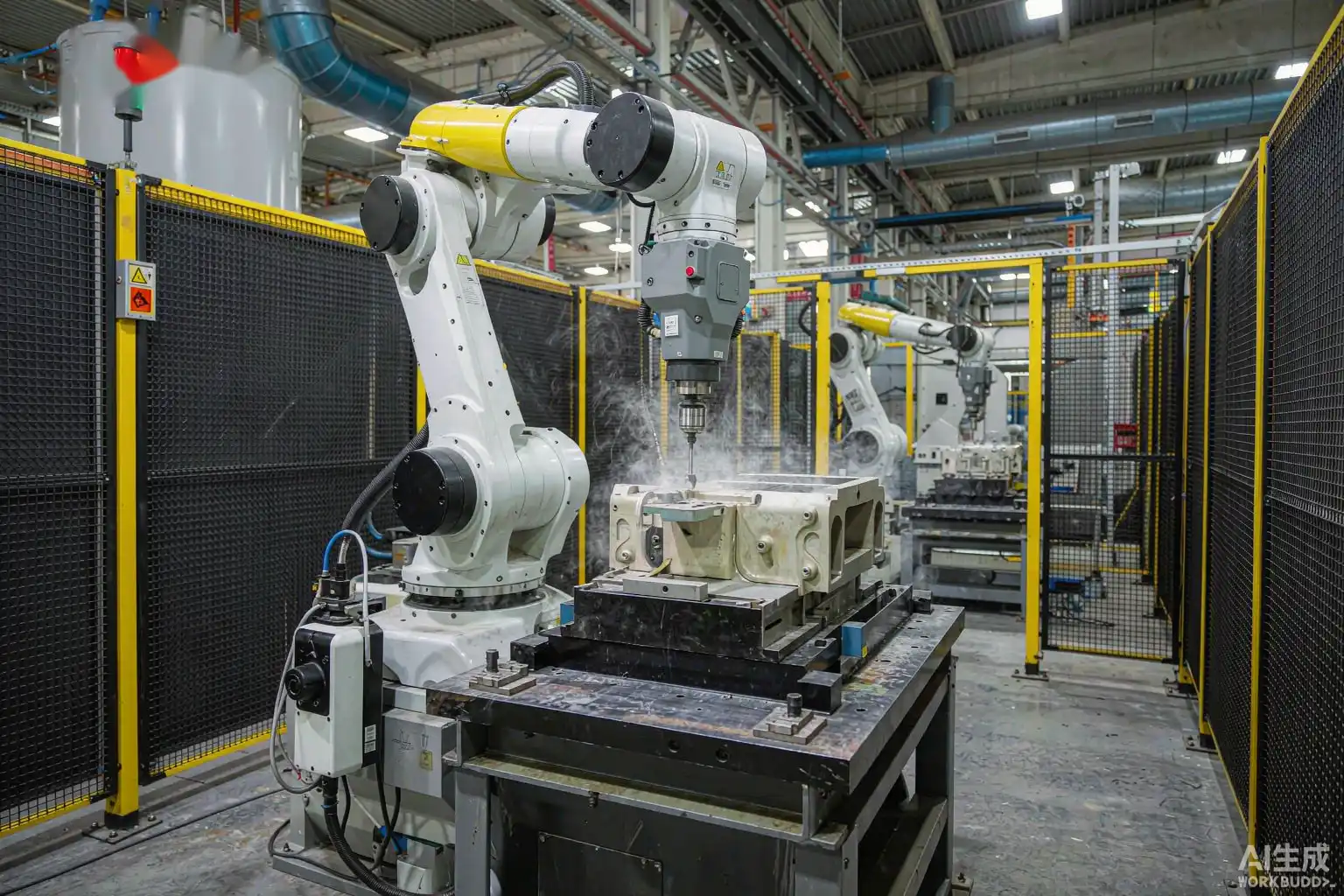
A robotic polishing machine for metal parts pairs an industrial 6-axis articulated robot with a compliant, compound-fed polishing head so it can smoothly trace complex 3D contours at constant normal contact pressure. By integrating taught tool paths, real-time closed-loop force feedback, and accurate automatic polishing compound application, automated surface finishing cells reliably convert rough ground castings into uniform satin finishes or defect-free optical mirror surfaces.
In high-volume metal processing, traditional manual polishing creates significant operational challenges: rapid operator fatigue, high scrap rates from uneven hand pressure, and dangerous workplace exposure to metal dust and particulate matter. Industrial robotic finishing cells replace subjective human craft with repeatable engineering parameters, ensuring identical surface quality across high-mix, low-volume and mass production runs alike.
The Core Operating Loop: Closed-Loop Mechanics and Force Feedback
At the mechanical heart of every automated finishing cell is an integrated real-time feedback system. The 6-axis robot presents the metal casting to the polishing spindle (or manipulates a mobile tool head around a fixed workpiece) along programmed spatial vectors. Simultaneously, a multi-axis force/torque sensor constantly measures tool engagement forces.
Liquid or solid compound is automatically dispensed onto the buffing wheel according to dynamic cycle counts rather than visual estimation, maintaining precise cut aggressiveness without burning binder residue. This active compliance principle operates similarly to a heavy-duty robotic grinding machine, but relies on soft media (cotton, felt, or sisal buffs) and fine abrasive slurries to refine surface topography rather than remove heavy material.
Step-by-Step Robotic Polishing Execution Sequence
An automated polishing program follows a tightly controlled kinetic sequence designed to optimize tactile dwell time and minimize tool wear:
- Automated Precision Fixturing: The raw metal part is pneumatic clamped in a custom end-effector or station fixture, repeatable within ±0.1 mm to eliminate tool collision risks.
- Kinematic Path Execution: The robot arm traces pre-programmed 3D contours at defined surface speeds (typically 15 to 35 m/s) and specified spindle RPM.
- Metered Compound Injection: High-pressure spray guns dispense liquid compound emulsions in precise 0.5 to 2.0 ml micro-doses directly onto the wheel contact zone per cycle.
- Active Force Compliance Adjustment: Pneumatic or active electric compliance units dynamically adjust the tool contact depth within milliseconds to compensate for casting dimensional tolerances and wheel diameter erosion.
- Automated Quality Routing: Once the programmed surface refinement cycle completes, the robot transfers the finished part to an inspection station or good/reject lane based on sensor validation.
Why Active Force Control is Essential for Reflective Finishes
Polishing acts as an optical amplifier: every variation in surface contact pressure alters the micro-groove depth left by abrasive grains. When a rigid robot arm executes a fixed path across curved geometry, minor part thickness variations cause drastic pressure spikes. This results in unsightly light/dark optical bands, gouges, or severe edge rounding.
Active force compliance resolves this by decoupling spatial positioning from contact force. The compliance head acts like a precise spring, applying an exact, continuous normal force (e.g., 20 N ±0.5 N) across freeform surfaces. Our detailed robotic polishing quality guide illustrates how force compliance eliminates surface streaking and haze on delicate zinc alloy automotive trim and plumbing hardware.
Recommended Operational Parameters by Substrate
Selecting appropriate speeds, wheel types, and compliance pressure is essential to balance cycle time against wheel longevity across different metals:
| Metal Alloy Type | Recommended Wheel Media | Spindle RPM / Speed | Target Compliance Force |
|---|---|---|---|
| Zinc Die Castings | Soft bias-cut cotton buff | 1,800 – 2,400 RPM (20 m/s) | 12 N – 20 N |
| 304/316 Stainless Steel | Treated sisal + ventilated cotton | 2,800 – 3,800 RPM (32 m/s) | 30 N – 50 N |
| Aluminum Alloy (6061/A380) | Open-mesh flannel or soft cotton | 2,200 – 2,800 RPM (25 m/s) | 15 N – 25 N |
| Brass and Copper Components | Unbleached stitched cotton mop | 2,000 – 2,600 RPM (22 m/s) | 18 N – 28 N |
QUICK PROCESS TIP
Dose polishing compound strictly by cycle count and timer, not by operator visual inspection. Over-application leads to grease accumulation and surface haze, while under-application causes severe dry friction burn marks.

Transitioning From Pre-Grinding to Fine Polishing
Automated surface finishing requires a disciplined multi-stage workflow. Polishing compounds cannot remove severe casting part lines or deep parting flash; attempting to do so destroys buffing wheels prematurely and causes inconsistent surface geometry.
Most production facilities integrate a multi-cell layout where automated belt grinding stages remove parting lines and establish a uniform target roughness (Ra 0.8 µm), followed by a transfer conveyor into the robotic buffing cell for high-gloss coloring passes. Reviewing our comprehensive robotic polishing cell setup guide will help you effectively design material handling and cell sequencing.
Troubleshooting Common Robotic Polishing Defects
When automated finishing quality drops below engineering specifications, use this defect troubleshooting matrix to locate process anomalies:
| Defect Name | Primary Root Cause | Corrective Action |
|---|---|---|
| Thermal Surface Burn | Excessive RPM or insufficient compound lubrication | Lower spindle RPM and increase liquid spray frequency |
| Cloudy Surface Haze | Skipped pre-grinding grit or excessive grease binder | Ensure pre-grind reaches Ra < 0.4 µm; optimize dosing volume |
| Shadow Banding Lines | Rigid path execution with uncompensated force spikes | Calibrate active force compliance and smooth robot trajectory |
| Edge Distortion / Over-Buffing | Excessive normal force or excessive dwell time on corners | Reduce compliance pressure over sharp radii; speed up robot robot TCP speed |
Frequently Asked Questions
What rotational speed (RPM) is optimal for robotic polishing?
Polishing operates at substantially lower speeds than grinding to prevent compound sling-off and thermal burning—typically between 1,500 and 3,500 RPM, translating to a wheel surface velocity of 20–30 m/s depending on wheel diameter.
Can a single robotic cell handle both coarse cutting and high-gloss buffing?
Yes. Dual-spindle stations or automated tool changers allow a single 6-axis robot arm to perform heavy cutting passes on a sisal wheel, then switch to a soft cotton wheel with fine coloring compound within the same cycle enclosure.
How do I prevent thermal burn marks on stainless steel castings?
Thermal burn occurs when dry friction generates localized heat exceeding the binder oxidation threshold. Maintain active force compliance under 35 N, utilize metered liquid emulsion sprays, and ensure linear tool speeds do not drop below programmed feed rates.
How does active force compliance compensate for buffing wheel wear?
As cotton buffing wheels wear down during continuous operation, their outer diameter shrinks. Active force sensors detect subtle drops in resistance force and automatically drive the robot tool center point (TCP) closer to the wheel, holding contact pressure perfectly steady throughout the wheel’s lifespan.
Need Help Specifying the Right Machine?
Selecting and sizing an automated finishing system requires careful matching of robot payload, force sensor dynamics, and spindle power to your specific part geometry and cycle time requirements. Talk to the application engineers at Xiamen Dingzhu Intelligent Equipment — we design custom grinding, polishing, and surface finishing systems tailored precisely to your alloy castings, target volume, and finish parameters. Explore our full range of heavy-duty automatic grinding machines and 6-axis automatic polishing machines today.