Die Casting Venting and Exhaust Design to Cut Air Entrapment
Where Trapped Air Actually Ends Up
In high-pressure die casting the cavity is never empty when the shot starts; it is full of air at roughly 1 atm, plus any gases driven off the die lube and the shot sleeve. The gating system pushes metal in and the air has to get out, or it is compressed and trapped. The first principle of venting is that air follows the last-fill zone. Whatever the gate geometry, the air pocket ends up where the metal fronts meet, and that is where vents must be.
We map trapped air in three zones:
- The last-fill zone of the cavity, where two or more flow fronts converge and squeeze a bubble between them. This is the classic location for a round, smooth void that X-ray reads as porosity.
- Deep pockets and cores, where the metal wraps a core and the air is pocketed behind it. These voids sit at the base of the core and are hard to reach by venting through the parting line.
- Machined faces, where a shallow trapped bubble ends up just under the surface that a later operation will cut. The machinist opens the bubble, and the face shows pitting that no polishing step can close.
Trapped air is not the same as shrinkage porosity. Air entrapment gives round, smooth-walled voids with no feeding pattern; shrinkage gives angular, dendrite-lined voids in thick sections. Confusing the two wastes effort: you cannot vent away shrinkage, and you cannot feed away air. We classify by sectioning and by X-ray, then size the fix to the mechanism. Where air is the cause, the porosity causes and solutions diagnosis starts with the vent layout, not the alloy.
Vent Depth by Alloy and Machine Lock Force
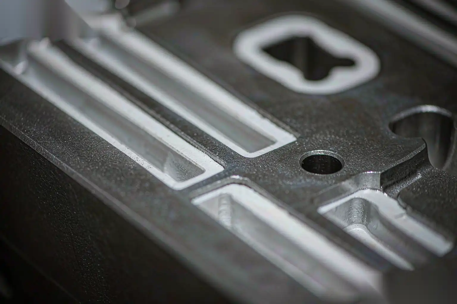
A vent is a shallow channel cut into the parting line (or a core) that lets air escape while the metal is still far enough from the cavity to be stopped by the vent’s shallow depth. The metal will not flash into the vent if the vent depth is below the gate-restricted metal’s ability to enter; in practice the limit is set by the clamping force and the alloy’s fluidity. Too deep and the clamp cannot hold the parting line, so metal flashes into the vent and the part sticks; too shallow and the vent clogs with oxide in a few shots and stops working.
The starting vent depths we use:
| Alloy family | Typical vent depth (mm) | Machine lock force range | Notes |
|---|---|---|---|
| Aluminum (A380, A356) | 0.08-0.13 | 280-900 ton | Shallower near thin walls; 0.10 mm is a common default |
| Aluminum, thin-wall | 0.06-0.10 | 400-1200 ton | Risk of clogging; need clean melt |
| Zinc (Zamak, ZA) | 0.04-0.08 | 80-400 ton | Lower temp, lower fluidity, shallower safe |
| Magnesium (AZ91) | 0.10-0.15 | 300-900 ton | Higher fluidity, watch flash |
These are launch values. The constraint is clamp tonnage versus projected area: if the cavity pressure at fill times the projected area approaches the lock force, the parting line opens and a deep vent flashes. We compute required lock force as cavity pressure (commonly 40-90 MPa at the gate, lower at the vent) times projected area, add 15-20% margin, and set vent depth so the parting line stays seated. A 660-ton machine holding a 350 cm² projected area at 60 MPa needs about 210 tons of clamp just for cavity pressure; the rest is margin for the runner and the vent’s own pressure.
Vent width and total vent area matter as much as depth. A vent that is deep but 2 mm wide cannot pass the air volume in 25 ms. We aim for total vent area such that the air can evacuate at the fill velocity; a rule we use is total vent cross-section equal to at least the gate cross-section, often two to three times, spread across the last-fill zones.
Geometry of where the vent opens also sets how well it works. A vent that opens into a dead pocket fills with flash and stops; a vent that opens into a relief that is 3-5 mm deeper than the slot and at least 4-6 mm wide on each side keeps working. We also angle the relief away from the cavity so escaping air and any flash dump outward, not back toward the part. On a tool with several last-fill zones we place vents at each, not one large vent at the largest zone, because air will not travel sideways to a distant vent during a 25 ms fill. The vent should sit directly in line with the flow front’s arrival direction so the air is pushed straight out, not around a corner where it stalls.
Exhaust Channels Versus Porous Steel
There are two main ways to get air out past the parting line: machined exhaust channels and porous (sintered) vent inserts. Each has a place.
Machined exhaust channels
A machined vent is a shallow slot in the parting line that opens into a larger exhaust relief (a pocket cut deeper than the vent so the escaped air and any flash can dump without blocking the slot). Advantages: cheap, easy to cut, easy to clean, and you can make it exactly where the last-fill zone is. Disadvantages: it clogs with oxide and lube residue, and it must be cleaned every shift or it loses area. We design the exhaust relief at least 3-5 mm deep behind the vent so a little flash does not bridge the slot.
Porous sintered steel inserts
A porous insert is a sintered metal plug placed in the parting line or core that lets air through its pores but blocks liquid metal because the pores are below the flash threshold. Advantages: very high effective vent area in a small footprint, reaches zones a parting-line slot cannot, and stays open longer. Disadvantages: the pores plug with lube and oxide and must be burned or ultrasonically cleaned on a schedule; they are a consumable; and they need the same depth discipline as a machined vent or they flash.
We choose by access and clog rate:
- Last-fill zone on the parting line, easy to reach: machined vent with a deep exhaust relief.
- Deep core or pocket where a parting-line slot cannot reach: porous insert at the core base.
- High-lube, high-cavity-pressure job: porous inserts plus a machined vent, cleaned on a fixed interval.
A mixed strategy is common. On a faucet body with a deep threaded boss, we put a porous insert at the base of the boss core and a machined vent at the opposing last-fill edge. The insert catches the pocket air; the machined vent catches the bulk. Both are on the cleaning schedule.
Vacuum-Assisted Venting
Vacuum venting removes the air before the shot arrives, instead of relying on the metal to push it out. A vacuum valve on the cavity pulls the air down to 50-200 mbar absolute just before the plunger moves, so the fill happens into a near-empty space. The result is fewer and smaller entrapped bubbles and, for cosmetic or pressure-tight parts, a step change in yield.
We specify vacuum venting when any of these hold:
- The part is pressure-tight (valve body, pump housing) and leak test rejects from porosity run above 3-5%.
- The cosmetic face must be pore-free after polishing, and mechanical polishing would open shallow bubbles.
- The wall is thin (under 1.5 mm) and the flow path is long, so there is no time to push air out through vents.
- The customer requires vacuum by spec, common in automotive and plumbing certifications.
Vacuum changes the vent design. With the cavity pre-evacuated, the vents can be deeper and the fill velocity can be higher without entraining air, which lets you fill faster and reduce freeze risk on thin walls. But the vacuum valve must seal against the shot; a leaking valve pulls metal into the vacuum line and stops working. We size the valve bore to the cavity volume and the pump capacity so the cavity reaches target vacuum within the machine’s dead time before the plunger advances. A vacuum die casting guide covers the valve timing and pump sizing in detail, but the gating rule still applies: vacuum does not fix a badly balanced fill, it only removes the air that a good fill would have left behind anyway.
Cost note: vacuum adds a valve, a pump, a controller and a cleaning cycle. We justify it by the avoided scrap on pressure-tight or cosmetic parts, not as a default on a simple bracket.
How Poor Venting Creates Porosity No Polish Can Hide
Polishing and grinding remove material from the surface; they cannot fill a void below it. A part with a bubble 0.2 mm under a cosmetic face looks fine as cast, then after the robotic polishing cell cuts 0.05-0.15 mm the bubble opens into a pit. The operator sees “polishing defect” but the root cause is the vent. We see this most often on:
- Plumbing spouts and handles where the visible face is also the last-fill face.
- Enclosure lids where a machined sealing face intersects a trapped-air zone.
- Decorative trim where a shallow bubble under the chrome or anodize layer breaks the coating.
The chain is: insufficient vent area at the last-fill zone → air compressed to a small bubble → bubble sits just under the surface → finishing cuts into it → cosmetic reject. The fix is upstream, at the vent, not at the polisher. We confirm by sectioning a rejected part at the pit and measuring bubble depth versus stock removal; if the bubble top is within the finishing stock, the vent is the cause.
This is why we design venting and finishing together. The finishing cell defines how much stock is removed at each face; we place vents so no trapped-air zone sits within that stock envelope of a visible or machined surface. For a part finished to Ra 0.4 after 0.10 mm of stock removal, any vent-induced bubble must be more than 0.10 mm below every finished face, or the vent layout must move.
Acceptance method we use on a new tool:
- Run the first 50 parts with the planned vents, then X-ray or section 5 parts across the cavity.
- Plot bubble depth against finished-face stock; reject any bubble within the stock envelope.
- If bubbles are present, deepen or widen the vent at the mapped last-fill zone, or add a porous insert, and re-verify.
- Only after venting passes do we lock the robotic polishing parameters.
Vent Maintenance and Process Control
A vent that works on shot one and clogs on shot 500 is a vent that was not designed for production. Lube and oxide build up in the slot and in porous inserts, and as area drops, air entrapment climbs and porosity rejects rise with no change to the alloy or the machine. We build maintenance into the design:
- Machined vents: clean every shift; record the last-fill zone and the slot depth after cleaning.
- Porous inserts: burn or ultrasonically clean on a fixed shot count (commonly every 3,000-10,000 shots depending on lube load); keep spares so the tool is not down.
- Vacuum valves: verify seal and pump vacuum each setup; a leaking valve is caught at first shot by the pressure trace.
We also track vent performance through the machine’s process data. A rising cavity pressure at fixed plunger velocity, or a later flow-front arrival in the simulation-vs-actual check, points to a clogging vent before parts fail. The process data monitoring approach turns vent maintenance from a guess into a scheduled action tied to real signals.
The DZ Smart Manufacturing team designs venting and the downstream robotic polishing and grinding cells as one package, so the vent layout accounts for the finishing stock and the polisher is not blamed for porosity it cannot fix. If you are seeing porosity rejects after finishing, send us the part model and a few rejected samples and we will map the trapped-air zone and propose a vent and finishing change together.