Porosity in Aluminum Die Castings: Causes, Inspection, and Prevention
Why Porosity Is the Most Important Die Casting Defect
Porosity causes more die casting failures than any other defect category. Unlike surface defects that are caught at inspection, porosity is often hidden inside the part, passing visual inspection and only revealed by:
- Machining (reveals subsurface voids)
- Pressure testing (leaks through interconnected porosity)
- Heat treatment (blistering from expanding gas)
- Welding (porosity in the weld)
- Anodizing (etches around porosity)
- Field failure (fatigue cracks initiate at porosity)
A part that passes all visual inspection can still fail in the field due to internal porosity. Reducing porosity is therefore a primary quality and reliability goal for any serious die casting operation.
The Two Types of Porosity
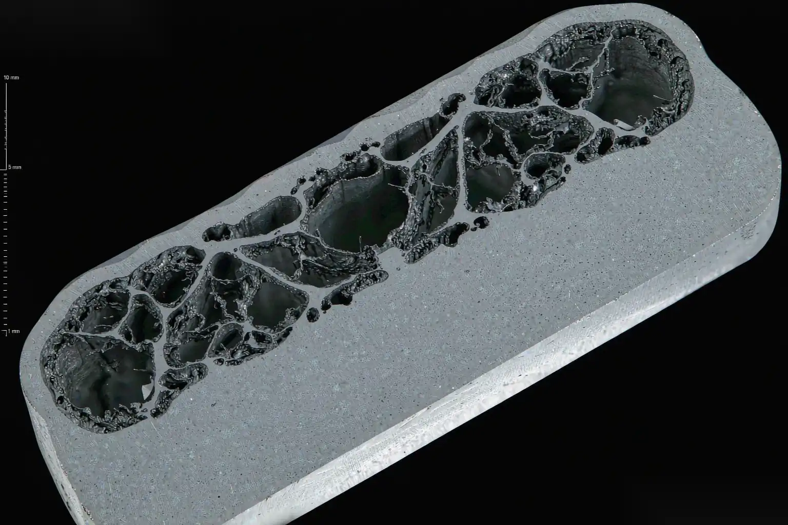
Gas Porosity
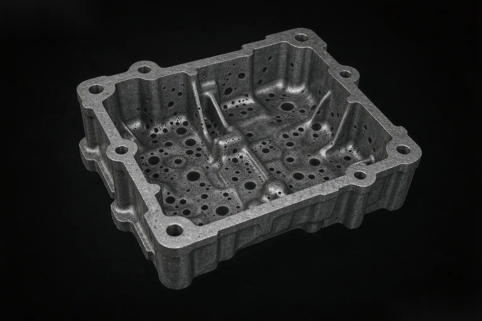
Cause: air or hydrogen trapped in the molten aluminum during injection, then frozen in place as the metal solidifies.
Appearance: round, smooth-walled voids, often 0.1-2.0 mm in diameter, distributed relatively uniformly throughout the part. Higher concentration near the surface in some cases.
Source of the gas:
- Air entrapment: the high-velocity metal flow traps air in the die cavity. This is the dominant source — typically 70-80% of gas porosity.
- Hydrogen absorption: molten aluminum absorbs hydrogen from moisture in the atmosphere, the alloy, or die spray. Hydrogen solubility drops sharply as the metal solidifies, so the hydrogen comes out of solution and forms voids.
- Die spray decomposition: excessive die spray or wrong die spray type can generate gas that gets trapped.
- Lubricant contamination: oil or grease in the die cavity vaporizes during injection.
Shrinkage Porosity
Cause: volumetric contraction as the molten aluminum solidifies. Aluminum shrinks about 6.5% by volume from liquid to solid. If the metal cannot feed liquid metal to compensate, voids form.
Appearance: irregular, dendritic (tree-like) voids, often elongated along solidification direction. Located at hot spots, thick sections, or where solidification happens last.
Source of shrinkage:
- Non-uniform wall thickness: thick sections solidify last; if the surrounding thin sections have already solidified, no liquid metal can flow in to compensate
- Inadequate intensification pressure: the pressure applied during solidification must be high enough to push liquid metal into the shrinking region
- Hot spots in the die: areas with insufficient cooling solidify last and create shrinkage
- Improper gate location: if the gate solidifies before the part, no feeding path exists
How to Inspect Porosity
Visual and Dimensional Inspection
Not effective for internal porosity. Surface defects may hint at porosity (raised bumps, sink marks), but cannot reliably detect it.
X-Ray Inspection
The standard non-destructive method for die casting porosity.
- 2D X-ray radiography: provides a shadow image of the part. Porosity appears as dark spots. Fast, relatively inexpensive, available from most NDT labs.
- CT (computed tomography) scanning: provides 3D visualization of porosity. Excellent for root cause analysis, expensive for routine inspection.
- Real-time X-ray on the production line: emerging technology, expensive, used for safety-critical parts (aerospace, medical).
Typical X-ray acceptance criteria for die castings:
- No individual pore larger than 2 mm in critical areas
- No cluster of small pores larger than 3 mm total area in critical areas
- No interconnected porosity (revealed by pressure testing or machining)
Metallographic Cross-Section
Destructive but definitive. A part is sectioned, mounted, polished, and examined under a microscope. Shows porosity size, shape, distribution, and relation to microstructure. Used for failure analysis and capability studies, not for routine inspection.
Pressure Testing
For parts that must hold pressure (hydraulic, pneumatic, water): leak test at 1.5-2.0x working pressure. Any pressure drop indicates interconnected porosity. Required for many OEM parts.
Ultrasonic Testing
Less common for die castings due to coarse grain structure, but used for some large parts. Detects porosity larger than 1-2 mm.
How to Reduce Gas Porosity
Vacuum Die Casting
The most effective single intervention. A vacuum system evacuates air from the die cavity before and during injection. Reduces gas porosity by 80-90%.
- Vacuum level: typically 50-100 mbar absolute pressure
- Cost impact: adds $30,000-100,000 to die casting machine cost, plus per-cycle time
- When justified: safety-critical parts, parts requiring heat treatment, pressure-tight parts
Improved Melt Degassing
Rotary degassing with argon or nitrogen removes dissolved hydrogen from the molten alloy.
- Degasser type: impeller or rotor-based, with argon or nitrogen injection
- Treatment time: 10-20 minutes per 500-1,000 kg melt batch
- Frequency: every batch, monitored with reduced pressure test (RPT) or equivalent
- Hydrogen target: below 0.10 ml/100g aluminum (RPT solidification time > 25 seconds indicates low hydrogen)
Die Spray Optimization
Reduce volume and improve application:
- Volume: typically 0.5-2.0 g per shot, depending on part size
- Dilution: typically 1:50 to 1:100 (concentrate:water)
- Application: minimal, focused on hot spots and slides
- Type: water-based with proper release agent, not oil-based
Slow Shot Phase Optimization
The first phase of injection (slow shot) pushes metal into the shot sleeve without trapping air. Optimize for:
- Speed: 0.1-0.3 m/s in the slow shot phase
- Profile: gradual acceleration to avoid wave formation in the shot sleeve
- Position: stop the slow shot at a defined fill level (typically 50-70% of the shot sleeve)
- Timing: minimize the time between slow shot and fast shot to prevent premature solidification
How to Reduce Shrinkage Porosity
Part Design for Uniform Cooling
The single most effective shrinkage prevention is part design:
- Uniform wall thickness (within ±25% of nominal) — primary design rule
- Avoid thick sections (over 4 mm for A380) unless functionally required
- Add fillets at thick-to-thin transitions (R0.5 minimum)
- Use ribs instead of thick walls to add stiffness without mass
- Place cores for hollow sections when possible
Die Cooling Design
Targeted cooling at hot spots:
- Cooling channels placed 8-15 mm from the die cavity surface
- Baffles and bubblers for complex cavity geometries
- Conformal cooling (3D-printed cooling channels) for highest performance
- Thermal simulation during die design to identify hot spots before steel is cut
Intensification Pressure
The pressure applied during solidification:
- Typical range: 60-100 MPa for HPDC
- Higher is better for shrinkage reduction, up to a limit
- Maintain intensification until the part is fully solidified — pressure drop during solidification causes shrinkage porosity
- Monitor with pressure sensor in the die cavity (advanced process control)
Gate Design and Location
- Gate thickness sufficient to remain open during solidification (typically 1.0-2.5 mm)
- Gate location that allows feeding from thick to thin sections
- Multiple gates for large or complex parts
- Overflow wells at the end of fill path to capture cold metal and air
Process Monitoring for Porosity Control
Modern die casting cells include:
- Shot profile monitoring — real-time display of shot speed, position, pressure
- Die temperature monitoring — thermocouples at key locations
- Cavity pressure sensing — pressure inside the cavity during injection
- Automatic process adjustment — closed-loop control of shot parameters
These systems detect drift that leads to porosity before the parts are produced. The investment pays back in 6-12 months on a high-volume production line.
Common Mistakes in Porosity Management
Treating Symptom Instead of Cause
Adding weld repair or impregnation to “fix” porosity without addressing the source. The parts still fail in the field, the rework is expensive, and the root cause is unchanged.
Overspecifying Porosity Limits
Setting X-ray acceptance criteria so tight that the supplier has to scrap 20% of production. The OEM pays either way — through high part cost or through constant quality disputes.
Ignoring Part Design Influence
The die casting supplier has limited ability to compensate for a part design that creates thick sections. The design review before tooling is the time to address this.
Skipping Process Capability Studies
Not running a proper Cpk study on porosity during sampling. The result is a part that passes T1 sampling but fails in production when conditions drift.
Porosity Acceptance Criteria: Writing Specs That Survive Production
Porosity specifications fail in two directions. Written too loosely, parts leak in the field and the warranty bill arrives. Written too tightly — “no porosity visible on X-ray” — the specification is unmanufacturable, and the program lives in a permanent quality dispute where every shipment is an argument. The workable middle ground defines porosity by zone and by function. Critical zones — sealing surfaces, machined faces, high-stress areas — get explicit limits: maximum individual pore size, maximum pore density per square centimeter, and no interconnected porosity, verified by leak test where the part must hold pressure. Cosmetic zones get surface-connected porosity limits only. Structural interior metal that carries no load can carry a generous general limit, because demanding perfection there only raises price.
Attach an X-ray reference radiograph to the drawing whenever possible. A photograph of the worst acceptable condition ends more porosity arguments than any paragraph of text.
Finally, decide porosity strategy before tooling, not after the first leak test fails. Vacuum assist, feed design, and intensification practice are tooling-era decisions; retrofitting them after PPAP costs multiples. When DZ Machinery audits a line for automated finishing, porosity at the machined edge is one of the first things we check, because edge porosity is what turns a stable deburring cell into a visual-inspection bottleneck. Specified correctly up front, the finishing cell stays a finishing cell instead of becoming a defect triage station.
FAQ About Aluminum Die Casting Porosity
What is the acceptable porosity level for a die cast aluminum part?
It depends on the function. For non-critical cosmetic parts, surface-connected porosity is unacceptable but internal porosity below 1 mm is generally acceptable. For pressure-tight parts, no interconnected porosity. For fatigue-loaded parts, porosity at the surface or at high-stress areas must be minimal. Specify the acceptance criteria based on function.
Does vacuum die casting eliminate porosity?
No — vacuum die casting eliminates most gas porosity but does not affect shrinkage porosity. For zero porosity, you need a different process (e.g., squeeze casting, investment casting) or design changes.
How much does vacuum die casting cost?
The die casting machine costs $30,000-100,000 more than a standard machine. Per-part cost increases 10-30% due to longer cycle time and equipment amortization. Justified for parts where the cost of failure is high (safety, warranty, brand reputation).
Can porosity be repaired?
Weld repair (TIG) can fill surface-connected porosity. Impregnation (vacuum sealing with sodium silicate or resin) can seal interconnected porosity. Both are workarounds, not solutions. The goal should be to prevent porosity, not repair it.
Building a Porosity-Free Process
A die casting process that runs with acceptable porosity requires:
- Part design that supports uniform cooling (DFM review)
- Die design with proper cooling and gating (thermal simulation)
- Alloy with controlled hydrogen level (degassing)
- Process parameters that minimize air entrapment (vacuum or optimized slow shot)
- Process monitoring that detects drift (shot profile, cavity pressure)
- Inspection that catches any escapees (X-ray on critical parts)
This is a system, not a checklist. Each element reinforces the others.
At DZ Smart Manufacturing, our robotic inspection cells detect visible porosity and surface defects at the next station, providing 100% inspection that human inspectors cannot match. If you are struggling with porosity escapes to the customer and want to see how automated inspection combined with process monitoring can improve your first-pass yield, our engineering team can review your process data and recommend specific improvements.