X-Ray and CT Inspection for Die Castings: Finding Internal Defects
Why you should not always cut the part open
When a die casting fails in the field, the classic engineering response is to section it. Cut it, polish it, etch it, and look at the cross-section. Sectioning is definitive for the slice you cut, but it destroys the part, it samples one plane out of thousands, and it tells you nothing about the other 99 percent of the volume. For a high-value aluminum housing or a pressure-bearing valve body, cutting apart every suspect unit is expensive and it still misses defects that happen to lie off the cut plane.
X-ray radiography and computed tomography (CT) change the equation. They are non-destructive, they see the whole volume, and they let you keep the part afterward for a leak test or a customer return. This article covers when radiography or CT beats sectioning, what internal defects they find, the density and resolution limits set by alloy and voxel size, the cost and throughput trade against sampling, and how to feed the results back into gating and venting changes.
Radiography versus CT: two tools, different questions
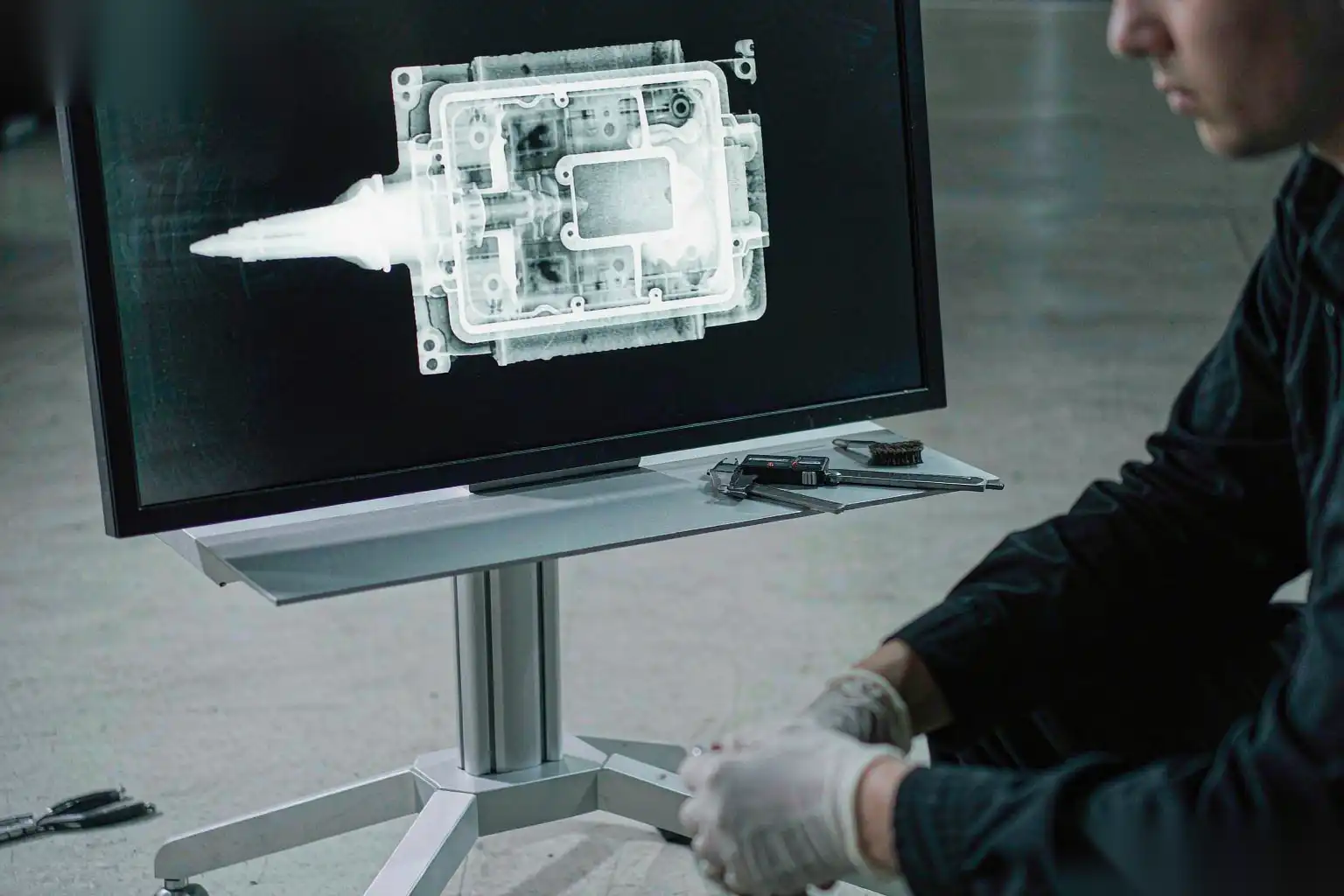
Plain radiography projects the part onto a 2D image. Density differences attenuate the beam, so a pore, a cold shut, or an inclusion shows as a lighter or darker spot. It is fast and cheap, and for a simple wall-thickness check or a gross porosity screen it is often enough.
CT rotates the part and reconstructs a 3D volume from many projections. You can then slice that volume virtually in any plane, measure a void’s volume, locate it in x, y, z, and even run a porosity percentage over a defined region of interest. CT answers the question radiography cannot: not just “is there a defect,” but “how big, where, and what does the internal geometry actually look like.”
Decision guide:
- Use radiography for high-volume, low-cost screening where you only need a pass-fail on obvious voids.
- Use CT for first-article validation, failure analysis, and any part where the defect’s position and volume decide acceptance.
- Use CT when the defect is near a feature radiography would superimpose over other geometry, such as a pore buried behind a rib.
The volumetric nature is the point. A sectioned sample proves the slice; CT proves the volume. For castings where a single isolated void in a sealed channel causes a leak, volume is what matters.
What X-ray and CT actually find
The defect catalog for aluminum die castings is short and well known, and X-ray sees most of it:
- Porosity. Gas pores from entrapped air or shrinkage voids from feeding failure. Radiography shows them as rounded dark spots; CT measures their true 3D volume and separates gas porosity (round, dispersed) from shrinkage porosity (interdendritic, clustered).
- Cold shut. Two flow fronts that met without merging, visible as a smooth linear or curved density change. It is a surface-connected or near-surface defect that radiography catches well when oriented to the beam.
- Inclusions. Oxide skins, die lube residue, or foreign particles with a density different from aluminum. Bright or dark depending on atomic number; oxides are close to aluminum in density so they are subtle and need good contrast.
- Cracks. Hot tears and solidification cracks show as fine dark lines, best seen when the crack plane is edge-on to the beam.
- Misruns and short fills. Low-density regions where metal never reached.
- Wall thickness variation and internal geometry. CT excels here, measuring actual wall sections against nominal CAD.
A porosity acceptance table we apply, scaled to the part’s function:
| Defect | Radiography visibility | CT capability | Typical acceptance |
|---|---|---|---|
| Gas porosity | Good | Volume and count | < 3 percent area in non-critical zone |
| Shrinkage porosity | Good | Cluster volume | None in seal zone |
| Cold shut | Good if oriented | Length and depth | Zero in pressure face |
| Oxide inclusion | Poor to fair | Possible if dense | Zero in machined bore |
| Crack | Fair, beam-dependent | Length, 3D path | Zero |
| Wall thickness | No | Yes, full map | Nominal plus or minus 0.2 mm |
The porosity causes and fixes are detailed in aluminum die casting porosity causes solutions, which is the document to open when CT shows a porosity pattern rather than an isolated void.
Density and threshold limits by alloy
X-ray contrast comes from differences in X-ray attenuation, which scales with density and atomic number. Aluminum at about 2.7 g per cubic centimeter is a low-atomic-number, low-density material, so the contrast between sound aluminum and a gas pore (density near zero) is excellent. The contrast between sound aluminum and an oxide inclusion (alumina around 4.0 g per cubic centimeter) is moderate and can be missed if the exposure is set for pore detection.
Practical limits:
- Gas pores down to roughly 50 to 100 micrometer in diameter are detectable on a good micro-focus system, but only if the voxel size is smaller than the pore.
- Oxide and sand inclusions need higher contrast settings and sometimes a higher tube voltage with careful filtering; they sit at the edge of detectability for thin sections.
- Zinc alloys, denser than aluminum, attenuate more and need adjusted voltage; the same void fraction is visible but the penetration depth is shorter.
- Very thick sections, over about 40 to 50 mm of aluminum equivalent, approach the system’s penetration limit and image noise rises, reducing small-void sensitivity.
- Thresholding for porosity percentage is operator-sensitive. The gray-value cutoff between “pore” and “sound metal” must be defined and locked, or two analysts report different porosity numbers on the same CT volume.
This is why CT is not a black box. The tube voltage, the filter, the exposure, and the threshold are engineering choices that decide whether a given defect class is visible at all.
Voxel resolution versus defect size
CT resolution is set by the voxel size, which is the reconstructed cube edge length. Voxel size is roughly the field-of-view diameter divided by the detector pixels. A 100 mm part on a 2000-pixel detector gives about 0.05 mm voxels; a 300 mm part on the same detector gives about 0.15 mm voxels.
The rule of thumb: you need at least two to three voxels across a defect to resolve it confidently. At 0.05 mm voxels you resolve a 0.15 mm void; at 0.15 mm voxels you need a 0.45 mm void. Smaller defects are invisible not because they are absent but because the reconstruction cannot see them.
Trade-offs:
- Smaller voxel requires a smaller field of view, so a large part must be scanned in sections or at lower magnification, increasing scan time.
- Higher magnification reduces penetration depth and increases scan time per volume.
- A typical production CT scan of a 150 mm aluminum part at useful resolution runs from several minutes to tens of minutes depending on the desired voxel and the tube power. That is the throughput constraint discussed below.
- Micro-CT pushes voxel size below 10 micrometer but only for small samples, useful for failure analysis of a cropped coupon rather than a whole housing.
When specifying CT, state the minimum defect size you must catch and let that drive the voxel, not the other way around. A spec of “detect all voids above 0.3 mm” is achievable on a full part; “detect all voids above 0.1 mm” may force micro-CT on a sample, not the production unit.
Cost, throughput, and the sampling question
Radiology and CT are slower and more expensive per part than a CMM touch or a visual check, so they rarely run 100 percent on high-volume lines. The engineering question is how to sample.
Considerations:
- Radiography can be fast enough for 100 percent screening on simple parts at a few seconds per image, especially offline or at a dedicated station. CT is too slow for full-volume 100 percent on most production rates.
- Use CT for first-article and periodic validation, for any field return, and for a statistical sample (for example one in fifty or one per die cavity per shift) to track porosity trend by cavity.
- Tie the sample rate to the process capability. Stable vacuum-assisted cells can sample lightly; turbulent, non-vacuum pours need heavier sampling until CT proves the trend is flat.
- The cost of a missed internal defect usually dwarfs the cost of a CT sample. A leaking valve body that reaches a customer carries warranty, freight, and reputation cost far above the price of a periodic scan.
- Build a defect library from CT so that cheaper radiography can be trained and validated against it. Radiography becomes the screen; CT is the reference standard.
Process monitoring linkage matters here. The data strategy in die casting process data monitoring explains how to log injection parameters so that when CT finds a porosity cluster you can correlate it to a specific machine, shot, and cavity rather than guessing.
Linking results to gating, venting, and process changes
The value of CT is not the pretty 3D image. It is the change it forces in the die and the process.
A typical feedback loop:
- Porosity near the last-filled region means poor feeding or premature freeze. Open the gate, add a overflow well, or raise the third-stage velocity. The porosity fixes in aluminum die casting porosity causes solutions map the defect location to the die change.
- Porosity along the parting line or in the first-filled area points to air entrainment. Improve venting, add a vacuum assist, or reduce pour turbulence. The venting design guidance complements this directly.
- Cold shut on a remote rib means that flow front lost temperature. Reroute the runner to feed that rib earlier or reduce its distance from the gate.
- Inclusions clustered at a fixed location suggest die lube buildup or a damaged cavity surface at that spot; schedule maintenance there.
- Wall-thickness maps from CT reveal inconsistent fill; adjust the die insert or the cooling so the section matches nominal.
The full defect taxonomy and remedy hierarchy is in aluminum die casting defects and solutions. We treat CT as the confirmation step: the defect appears in the volume, the cause is traced through the defect guide, the die or process changes, and a follow-up CT proves the closure.
Practical acceptance plan for a casting line
A workable plan we recommend:
- Define critical zones on the CAD: seal faces, machined bores, pressure channels. Set zero-tolerance for cracks and cold shuts there.
- Set a porosity limit by zone, for example under 2 percent void fraction in critical zones, under 5 percent in structural zones, measured over a CT region of interest.
- Run CT on first article, on every die change, and on a periodic sample per cavity.
- Use radiography as the high-rate screen between CT checks, calibrated against the CT baseline.
- Record every CT volume against the shot number and cavity so a future field failure can be traced backward.
DZ Machinery builds die casting and finishing lines where X-ray or CT stations are integrated as a validation gate before robotic grinding and polishing, so internal defects are caught before value is added by finishing. Talk to our engineering team about your defect-risk profile and part geometry, and we will help lay out the inspection gate and the gating or venting changes the results demand.