Vacuum Die Casting: Realistic Porosity Reduction, Process Windows, and When It Pays
Vacuum die casting is sold as a porosity cure. It is not a cure; it is a reduction technique with a defined ceiling, and understanding that ceiling is the difference between a program that succeeds and a program that spends money on a vacuum system and still scraps parts. We use vacuum-assisted casting on a large share of the aluminium parts we later finish, mostly structural and pressure-tight housings, and we have also watched it specified on parts where it did nothing measurable.
This guide covers how the process actually works, the vacuum level and evacuation time targets we design to, what porosity reduction you can honestly expect, the measurement that proves it, and where vacuum changes downstream behaviour including heat treatment, welding and polishing.
What Vacuum Actually Does During the Shot
Air is the dominant gas source in high pressure die casting. The cavity, the runner and the shot sleeve are full of air at atmospheric pressure when the shot starts, and fill times of 40 to 80 ms do not leave that air much opportunity to escape through conventional vents. The compression ratio explains the damage: a cavity at 1000 mbar that traps air and compresses it under an intensification pressure of 60 to 80 MPa leaves gas pores at a residual pressure that is high enough to expand during heat treatment and to open as blisters under paint or plating.
Vacuum removes most of that air before and during fill. The pump pulls the cavity, runner and sleeve down to an absolute pressure typically between 50 and 200 mbar, so the mass of gas available to be entrained drops by roughly 80 to 95 percent. Less gas entrained means smaller and fewer gas pores, and — the part engineers often forget — less back pressure in the cavity, which means the metal front travels further and faster for the same plunger force. On thin-wall parts that secondary effect is frequently the bigger benefit: vacuum lets you fill a 1.2 mm wall at 250 mm flow length that would otherwise misrun.
Vacuum does not remove shrinkage porosity. Shrinkage comes from the roughly 6 to 7 percent volumetric contraction of aluminium on solidification, and it is addressed by feeding, gate freeze control and intensification. If your porosity is shrinkage-driven, vacuum will disappoint you.
Valve Types and Where They Sit
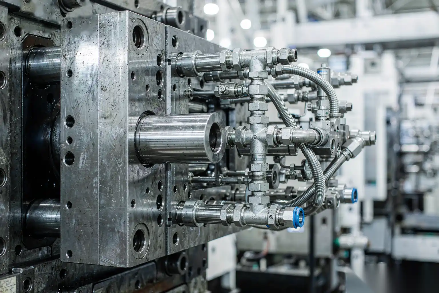
The valve is the component that decides whether a vacuum system survives production. Its job is to let air out and to stop before metal reaches it, and it has to do that on every shot for a tool life measured in tens or hundreds of thousands of cycles.
Mechanical shut-off valves
A mechanical valve uses the arriving metal front itself to push a piston or plate that closes the vacuum channel. They respond in a few milliseconds, which is why they are the most common choice. They sit in the die, close to the end of fill, and they need positive mechanical reset each cycle. Their weakness is contamination: aluminium fines and lubricant residue build up on the moving element, and a valve that sticks part-closed reduces evacuation and produces the intermittent porosity that is hardest to diagnose.
Chill block and wave-block valves
A chill block is a vent block with a labyrinth path sized so that metal freezes in the channel before it can reach the pump line. It has no moving parts, which makes it robust, but it depends on thermal balance. If the block runs hot, metal gets through; if it runs cold, the channel freezes early and evacuation stops before the cavity is full. Chill blocks need their own cooling circuit and a thermocouple, and they are temperature-sensitive in a way that mechanical valves are not.
Vacuum through the shot sleeve
Pulling vacuum from the pour hole or through the sleeve evacuates the largest gas volume in the system, because the sleeve above the metal is typically the single biggest air reservoir. It is usually combined with a die-mounted valve rather than used alone. The practical detail is the seal at the pour hole; a worn seal here leaks continuously and you will chase the symptom in the cavity for weeks.
Targets: Vacuum Level, Evacuation Time, Leak Rate
Three numbers define the process window, and all three should be on the setup sheet.
- Absolute pressure at the moment of fast-shot start. 50 to 100 mbar for pressure-tight structural parts; 100 to 200 mbar for general-purpose porosity improvement. Below about 50 mbar the marginal gain is small and the cycle time cost rises, because evacuation time grows roughly logarithmically as you approach the pump’s ultimate pressure.
- Evacuation time available. The vacuum must reach target before the plunger passes the pour hole, and it must hold until the valve closes. Typical available window is 0.5 to 2.0 s depending on the dry-cycle time and where the pour-hole seal engages. If you only have 0.4 s, no pump specification will save you; you need to re-sequence the cycle.
- System leak rate. A healthy die and vacuum line should hold below 250 mbar for 2 s after isolation. A rise faster than roughly 100 mbar/s indicates a leak at the parting line, a worn valve seat, a cracked line, or a missing O-ring on a core pull.
Pump capacity should be sized from the volume to be evacuated and the available time, not from a catalogue match to the machine tonnage. As a rough guide, evacuating 15 to 25 litres of cavity, runner and sleeve volume to 80 mbar within 1.2 s needs a pumping speed well above what a small vane pump delivers once line conductance losses are included.
Also worth recording: the vacuum level at which the valve closes, and whether it closes before or after the cavity is full. A valve that closes at 400 mbar because it is slow does not give you a 100 mbar result regardless of what the gauge read earlier in the cycle.
Realistic Porosity Reduction and How to Measure It
Here is the honest expectation, based on what we see in sectioned and X-rayed production parts.
| Condition | Typical gas pore size | Typical area fraction at a machined face | Leak rate before impregnation |
|---|---|---|---|
| Conventional venting, no vacuum | 0.3 to 1.5 mm | 1.5 to 4 percent | 5 to 15 percent |
| Vacuum at 150 to 200 mbar | 0.1 to 0.5 mm | 0.5 to 1.5 percent | 1 to 4 percent |
| Vacuum at 50 to 100 mbar, good valve | Below 0.15 mm | 0.2 to 0.6 percent | Below 1 percent |
| Shrinkage-dominated porosity, any vacuum level | Irregular, interdendritic | Largely unchanged | Poor, unaffected by vacuum |
Those are ranges, not promises, and they assume the rest of the process is under control. A tool with a bad plunger law will fold air in the sleeve and vacuum will not retrieve it.
The measurement matters as much as the process. Ranking from weakest to strongest evidence:
- Visual rating of a machined face. Cheap, fast, and too subjective to settle an argument.
- Density measurement by Archimedes method. Gives bulk porosity to roughly ±0.2 percent and is useful for trend monitoring, but averages over the whole part and hides local severity.
- X-ray or CT at the critical section. The right tool for a leak-critical zone. Set an acceptance criterion in pore diameter and pore density per unit area, not a vague “no visible porosity”.
- Pressure decay leak test at defined pressure and volume. The only method that answers the actual customer requirement. Specify test pressure, allowable decay, stabilisation time and temperature.
- Metallographic section with image analysis. The reference method for calibration. Cut the same location every time, measure pore area fraction and maximum pore diameter, and keep the numbers in a control chart.
We tell customers to pick one objective method, write the acceptance number into the drawing, and stop arguing about photographs.
When Vacuum Pays and When It Does Not
Vacuum pays when porosity is the constraint and the porosity is gas-driven. Concretely:
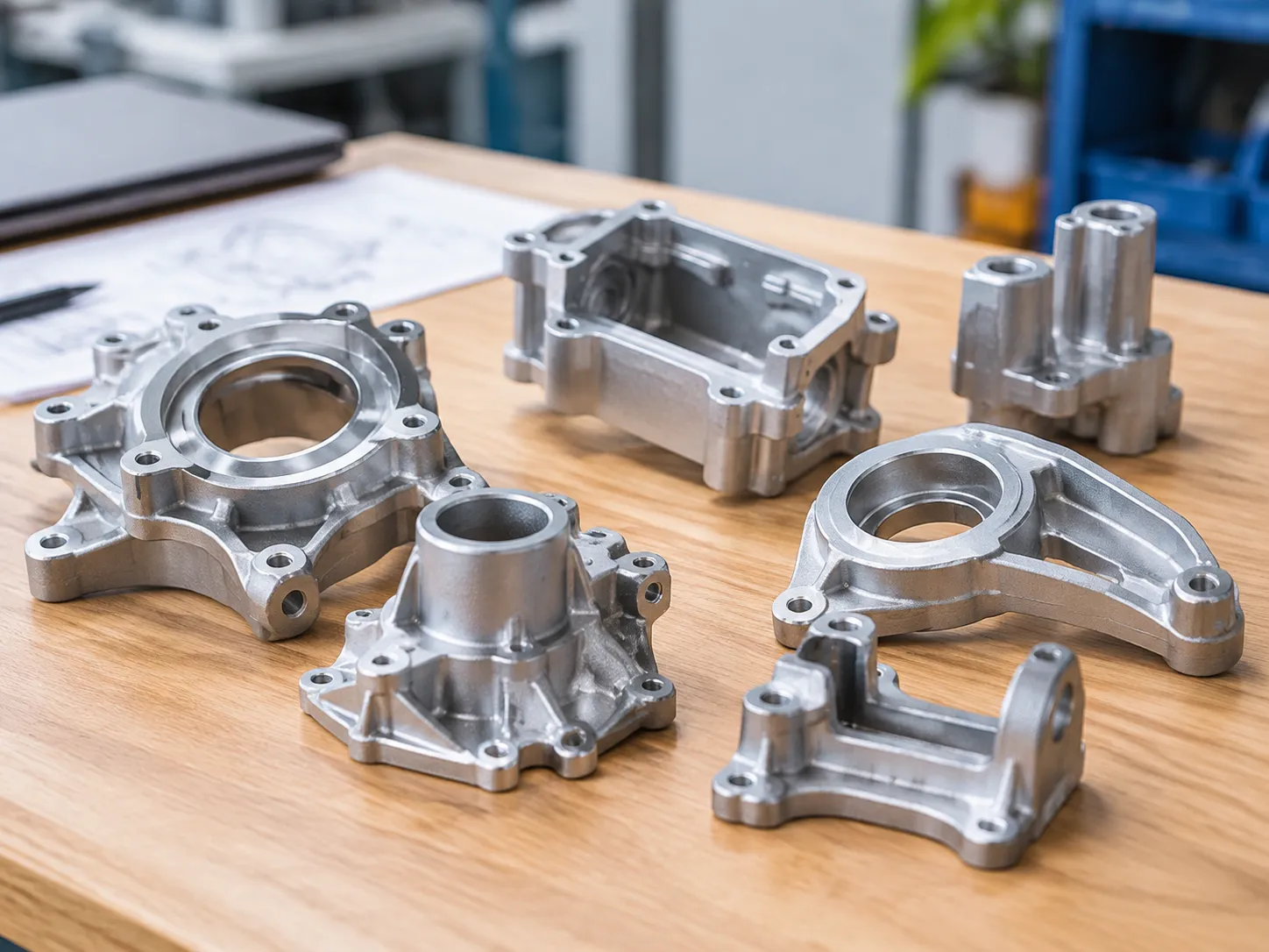
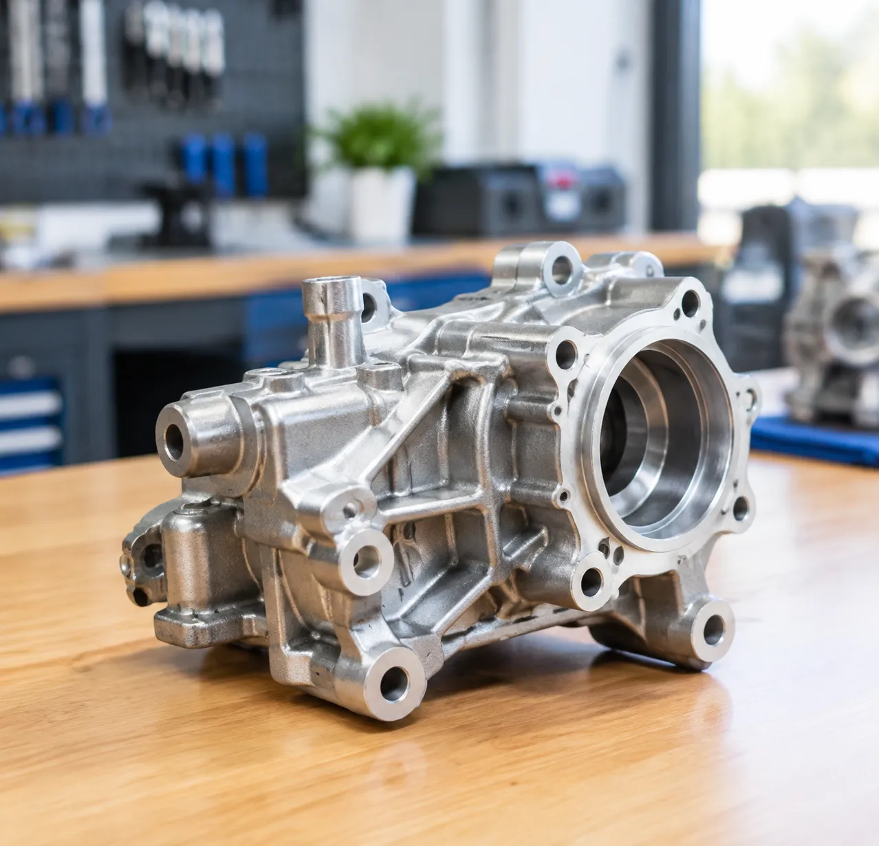
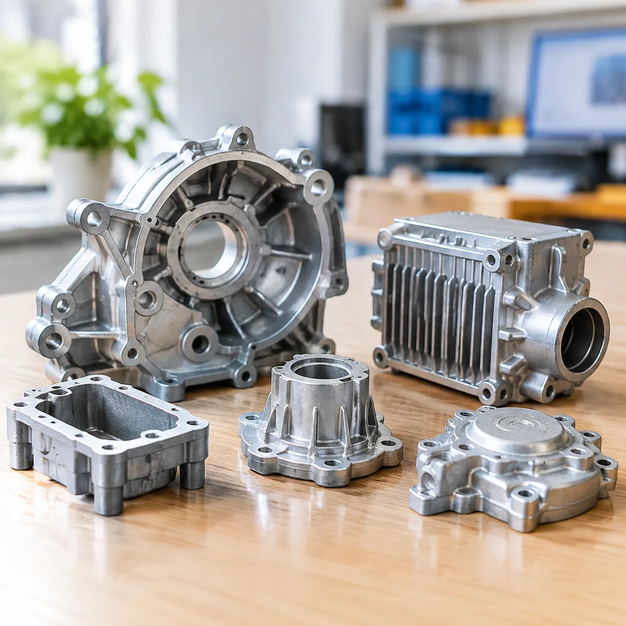
- Pressure-tight housings, valve bodies, pump bodies, compressor parts that must pass a leak test without impregnation.
- Parts that will be solution heat treated, welded, or high-temperature coated, where entrained gas expands.
- Thin-wall parts where fill is limited by cavity back pressure rather than machine capability.
- Parts where scrap cost per piece is high enough that a 2 to 4 percent yield gain covers the running cost quickly.
Vacuum does not pay when:
- The dominant defect is shrinkage, cold shut or flow mark. Fix feeding and thermal balance first.
- The part has no leak, structural or cosmetic-after-machining requirement. You are buying insurance against a failure mode nobody will test for.
- The tool leaks badly. Vacuum amplifies the value of good parting line condition; it cannot compensate for a die that will not seal.
- Cycle time is the binding constraint and there is no spare time in the cycle for evacuation. Vacuum typically adds 0.3 to 1.5 s per shot depending on volume and pump size. On a 25 s cycle that is a few percent; on an 8 s zinc cycle it is prohibitive.
The running cost is real and worth calculating before committing: pump and valve maintenance, filter and separator cleaning, additional die maintenance for the valve seat, and the yield loss while the system is being tuned. Against that, weigh avoided impregnation, avoided warranty claims and the yield gain.
Part Categories That Require Vacuum
Some categories effectively mandate it, because the acceptance test cannot be met otherwise:
- Pressure vessels and fluid handling bodies. Pneumatic valve bodies, hydraulic manifolds, water meter housings, pump volutes. Leak test at 5 to 10 bar with a decay limit measured in cm³/min is not achievable with conventional venting on anything but the simplest geometry.
- Structural and safety castings. Suspension and steering components, brackets that carry crash loads. Here the requirement is often elongation and fatigue life rather than leak tightness, and gas porosity above roughly 0.5 mm diameter is the crack initiation site.
- Welded assemblies. Any casting that will be MIG or TIG welded to another component. Gas in the fusion zone produces weld porosity and rework.
- High-temperature coated parts. Powder coating cure at 180 to 220 °C and anodising both produce blisters from near-surface gas. This is the most common cosmetic failure we see on parts that skipped vacuum.
- Thin-wall cosmetic parts with long flow length. Large trim panels and bezels where the fill limit, not the porosity limit, is the constraint.
Heat Treatability and Weldability
Standard high pressure die castings are not normally solution treated, precisely because entrained gas expands and blisters. Vacuum changes that calculation. With cavity pressure at 50 to 100 mbar and gas content reduced by an order of magnitude, T5 and limited T6 treatments become viable on alloys and geometries where they previously were not. The practical limits we work to:
- Solution treatment temperatures above roughly 480 °C remain risky even with vacuum, unless gas content is verified by sectioning on every lot.
- T5 artificial ageing at 150 to 200 °C is generally safe on vacuum cast parts and is commonly used for dimensional stabilisation before machining.
- Blister depth after treatment is the acceptance metric: any blister exceeding 0.3 mm on a cosmetic face is a reject, and a 1 percent blister rate is enough to make a heat treat route uneconomic.
Weldability improves for the same reason. Weld porosity in die cast aluminium is largely gas-driven, and vacuum-cast material produces noticeably cleaner fusion zones. You still need the correct filler, clean base material and controlled heat input, but the base material is no longer the limiting factor.
Keeping the Vacuum System Alive
Vacuum systems degrade silently, and the symptom is a slow increase in scrap that gets blamed on the alloy. A maintenance regime that works:
- Log vacuum level every shot. Modern systems record the pressure at fast-shot start and at valve closure. Trend it. A drift from 80 to 180 mbar over two weeks is a leak or a failing pump, and you want to see it before the customer does.
- Inspect and clean the valve every shift change at minimum, and strip it on a fixed cycle — daily for high-volume tools, weekly for others. Aluminium fines and lubricant coke are the enemy.
- Check line conductance monthly. A partially blocked filter or a crushed hose costs more vacuum than a pump upgrade recovers.
- Monitor pump oil and separator condition, and keep a spare valve cartridge on the shelf. A valve failure that stops a line for six hours costs more than the spare.
- Re-verify the leak rate after every die rework. A reworked parting line, a new core slide, or a replaced ejector pin can open a leak that no amount of pump capacity will overcome.
What Lower Porosity Means for Downstream Polishing
This is where vacuum shows up in our own numbers. Polishing a die cast surface is a battle against near-surface defects. A gas pore at 0.5 mm diameter under a polished surface is a visible pinhole the moment you bring the surface to a mirror finish; grinding it out means cutting deeper, which changes dimensions and lengthens cycle time; and a polished part with subsurface porosity will outgas or show defects after plating.
On vacuum-cast parts we see three consistent effects in the finishing cell:
- Reduced grinding depth. Less near-surface porosity means the abrasive sequence can start finer, so stock removal drops and dimensional scatter shrinks.
- Higher first-pass yield on cosmetic faces. Pinhole and blister rejects after polishing fall sharply, and with them the rework loop.
- More consistent polishing media consumption. Porous surfaces grab abrasive and loading behaviour varies from part to part; a dense surface behaves predictably, which is what makes an automated polishing cell repeatable.
The interaction with defect type is worth stating plainly: vacuum removes gas porosity, and gas porosity is the defect that automated finishing handles worst, because it is invisible until the surface is bright. Flow lines and cold shuts are at least visible and locatable. If you are planning an automated cell, the casting route matters as much as the cell specification, and aluminum die casting porosity causes and solutions is the natural companion to this discussion. For the surface specification side, see die casting surface finish standards, and for how we plan removal on porous castings, how to deburr aluminum die castings with automation.
DZ Machinery builds robotic grinding and polishing cells with compliant force control for die cast and faucet hardware, and we size those cells against the actual surface condition of your castings. If you are weighing a vacuum system, send us a sample batch with and without vacuum and we will run both through a finishing trial and give you the cycle time and yield difference in numbers.