Die Casting Machining Allowance and Datum Strategy: How Much Stock, Where, and Why
Machining allowance on a die casting is a decision that gets made by default far more often than by calculation. Somebody copies the value from the last drawing, or applies 1 mm everywhere, and the consequences surface months later as opened porosity, broken tools, warped parts, or a deburring cell that cannot hold a consistent edge.
We see the downstream end of this daily. A part with too little stock arrives at the finishing cell with cast skin still on the critical edge, and the robot has to cut deeper than programmed to clean it, which changes the edge radius part to part. A part with too much stock has a heavy interrupted cut that leaves chatter marks the polisher then has to remove, adding a station and a minute of cycle time.
This article sets out allowance values by feature type and size, the failure modes at both extremes, datum structure for cast-then-machine parts, fixture implications, and how the choice propagates into deburring and finishing.
What Machining Allowance Is Actually For
Allowance is not simply “extra metal to cut off”. It exists for four distinct reasons, and each implies a different number:
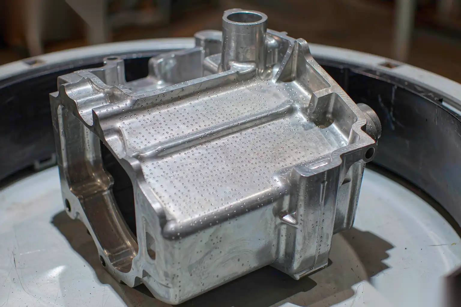
- Removing the cast surface layer. The as-cast skin on a high pressure die casting is dense and fine-grained for the first 0.1 to 0.3 mm, then gives way to a subsurface layer that contains gas pores, oxide films and lubricant residue. Machining below that layer gives a sound, consistent surface.
- Correcting dimensional variation. Casting tolerance across the parting line, and position tolerance between features in opposite die halves, is typically in the ±0.15 to ±0.5 mm band depending on size. Machining has to have enough stock to guarantee that the cut always reaches clean metal at the worst-case casting.
- Providing a locating and clamping surface. Some allowance is consumed purely to create a datum that the next operation can hold.
- Allowing for distortion. Trim, ejection and heat treatment all move the part. Allowance has to cover the worst-case movement or the cut breaks through in places.
The minimum allowance is therefore set by the sum of the worst-case casting deviation and the depth of the defective surface layer, not by a round number somebody likes.
Allowance by Feature Type and Size
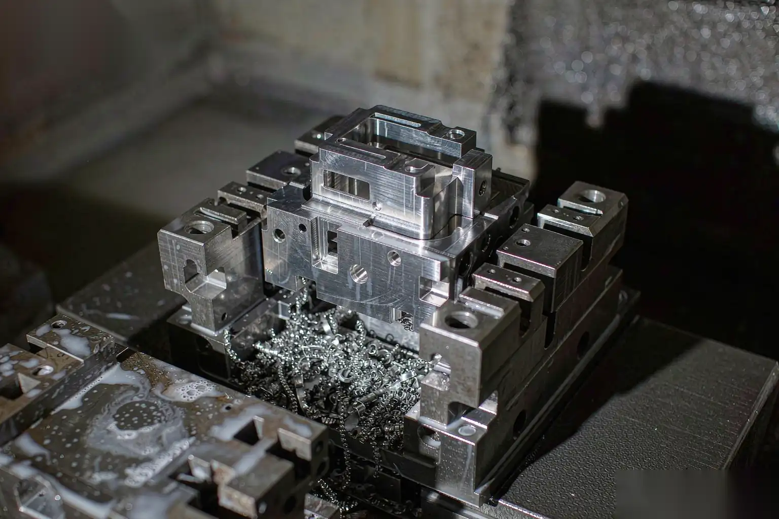
The values below are working numbers for aluminium and zinc high pressure die castings with conventional vacuum or standard venting, machined on CNC equipment with reasonable rigidity. Reduce them where casting capability is proven by capability study; increase them where the casting is large, thin-walled, or prone to movement.
| Feature | Small (under 100 mm) | Medium (100 to 300 mm) | Large (300 to 600 mm) | Notes |
|---|---|---|---|---|
| Flat face, single cut | 0.5 to 0.8 mm | 0.8 to 1.2 mm | 1.2 to 2.0 mm | Add 0.3 mm if the face is a sealing surface |
| Flat face, opposite a parting line | 0.8 mm | 1.0 to 1.5 mm | 1.5 to 2.5 mm | Covers parting line shift plus flash root |
| Bore, rough then finish | 0.6 to 1.0 mm on diameter | 1.0 to 1.5 mm | 1.5 to 2.5 mm | Core length and deflection drive the upper end |
| Boss face and counterbore | 0.8 mm | 1.0 mm | 1.5 mm | Bosses are shrinkage sites; do not skimp |
| Threaded hole, cast pilot | 0.5 to 0.8 mm on diameter | 0.8 to 1.2 mm | 1.2 mm | Pilot core must stay straight |
| Slot or groove | 0.6 mm per side | 0.8 mm per side | 1.0 mm per side | Interrupted cut needs more |
| Sealing groove, O-ring | 0.8 to 1.0 mm | 1.0 to 1.5 mm | 1.5 mm | Groove floor must be pore-free |
| Edge to be deburred only | 0 to 0.3 mm | 0 to 0.5 mm | 0 to 0.8 mm | See deburring note below |
Two adjustments matter. First, for zinc alloys, which cast to tighter tolerance and thinner walls, allowance can typically be reduced by 30 to 40 percent against the aluminium figures. Second, any feature machined in a second operation after the part has been released from its casting datums needs enough allowance to absorb the relocation error, which is where the upper end of these ranges comes from.
A useful sanity check: total allowance per face should be roughly 2 to 3 times the expected total casting variation on that dimension. If your casting study shows ±0.25 mm across the parting line, a 0.5 mm allowance is the mathematical minimum and 0.8 mm is the practical one.
Why Too Little Stock Exposes Porosity
Under-allowancing is the more dangerous error, because it produces a defect that passes incoming inspection and fails in service.
- The cut breaks through the sound skin into the pore layer. Gas porosity in a die casting is rarely uniform; it concentrates at 0.5 to 2.0 mm below the surface in thick sections and at the last-fill location. A face machined at 0.4 mm may expose a band of 0.3 to 0.8 mm pores that were invisible before the cut.
- Sealing faces leak. An O-ring groove floor with exposed interconnected porosity fails a pressure decay test. The fix is not deeper machining on the rejects; it is more allowance in the design, or vacuum casting.
- Plating and anodising defects. Subsurface gas that survives machining expands during anodising or powder cure, and the part blisters after it has already passed final inspection.
- Inconsistent appearance. A face that only partially cleans up shows islands of cast skin surrounded by bright machined metal. No polishing sequence recovers that cosmetically, because the two areas reflect differently regardless of surface roughness.
- Tool life and process stability. An intermittent cut that only engages on the high spots of a warped casting produces vibration, chatter, and variable tool load. That variability is what makes a machined surface inconsistent rather than merely wrong.
The test we use when reviewing a new drawing: take the worst-case casting from a capability study, measure the actual stock present at every machined feature, and confirm that the minimum is above the cut depth with margin. If that measurement has not been done, the allowance is a guess.
Why Too Much Stock Costs More Than You Think
Over-allowancing looks safe and is quietly expensive.
- Cycle time. Stock removal scales with volume, and on a face milling operation going from 0.8 to 1.5 mm allowance typically adds 20 to 40 percent to the cutting time on that face. Across a part with six machined faces, that is real money per piece.
- Tool life. More removed metal means more tool wear, more tool changes, and more variation as the tool wears through the batch.
- Heat and distortion. A heavier cut puts more heat into the part and releases more casting stress asymmetrically. Parts that were flat after casting can warp after an aggressive facing cut, and the warp is discovered at final inspection.
- More deburring. Every machined edge is a burr waiting to happen, and burr size scales with cut depth and feed. A 1.5 mm facing cut at the edge of a boss produces a substantially larger burr than a 0.6 mm cut.
- Scrap weight and remelt. On a part with 1 kg of machined-away material, that is 1 kg of swarf per piece to handle, separate and remelt.
The commercial point is that allowance is a shared cost. The casting designer specifies it, the machining supplier pays for part of it, and the finishing cell pays for the rest in burr removal. It should be set once, on evidence, across all three.
Datum Structure for Cast-Then-Machine Parts
Datum structure is where most cast-then-machine programs actually go wrong, more often than allowance itself.
The principle is simple: the datum features used to locate the casting for the first machining operation must be features that exist on every casting, in the same place, with repeatable geometry, and they must not be created by that same operation.
A workable three-two-one scheme for a typical housing:
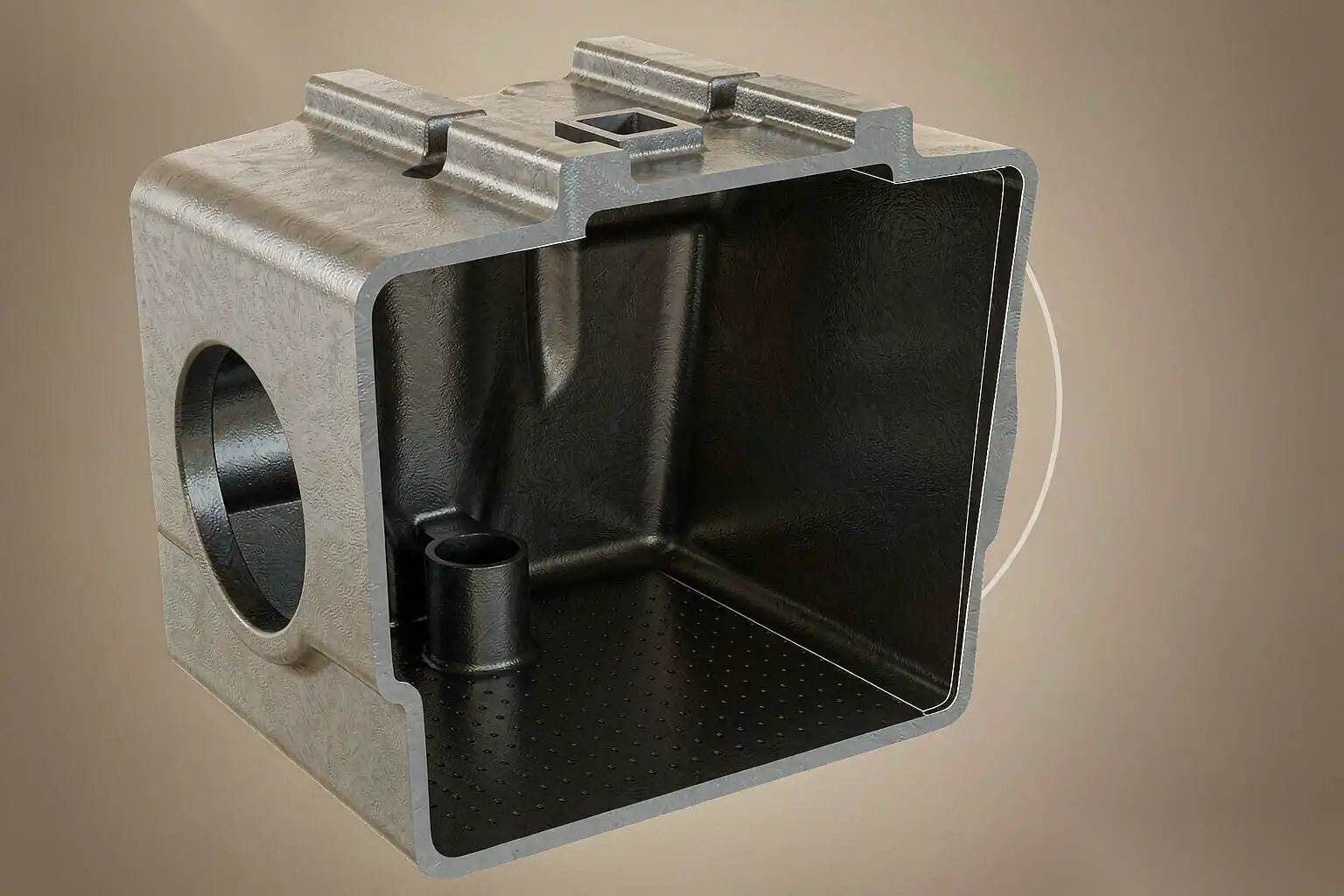
- Primary datum. Three points on the largest as-cast flat area, or on three pads deliberately added to the casting for the purpose. Three isolated pads are far better than one large flat, because as-cast flats are never flat and a three-point contact does not rock.
- Secondary datum. Two points on a second as-cast face, perpendicular to the primary, or on the side walls of two cored holes.
- Tertiary datum. One point on a third face, or one cast boss side, to stop rotation.
Design rules we apply:
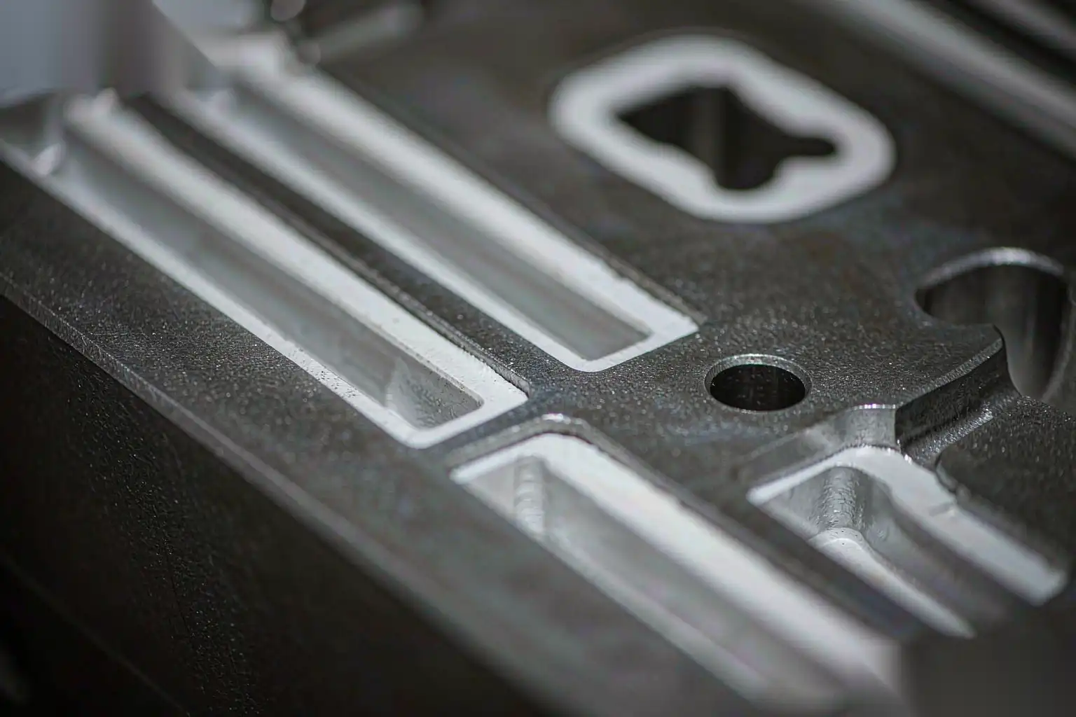
- Add machining pads to the casting. Three to four small raised pads, 8 to 15 mm diameter, coplanar as cast, cost almost nothing in the tool and transform fixturing repeatability. They are the single highest-value design change available on most parts.
- Keep all critical machined features referenced to one datum set. If a bore on one side is dimensioned from the parting line and a face on the other side from a cast boss, you are accumulating two independent variation sources.
- Machine the datums first if you need them later. For a two-operation process, operation 10 should create the precision datums that operation 20 locates on, and the allowance must include stock for those datum faces.
- Avoid datums that cross the parting line. Features formed by both die halves carry the parting line shift plus any die half misalignment, and they are the least repeatable features on the casting.
Locating from As-Cast Surfaces Versus Machined Datums
Both are valid, and the choice depends on what the tolerance requires.
Locating from as-cast surfaces is the normal first-operation approach. Its accuracy is limited by casting repeatability, typically ±0.1 to ±0.3 mm for locating on cast pads, and worse on large or thin parts. Advantages: no extra operation, no extra stock, and the datums are always there. Disadvantages: variation accumulates, and any casting distortion moves the datums with it.
Locating from machined datums is the correct approach for the second operation and for any tolerance tighter than roughly ±0.05 mm. Advantages: repeatability improves to the capability of the machine, typically ±0.01 to ±0.02 mm. Disadvantages: requires a prior operation to create the datums, requires allowance on those datum faces, and — critically — the part is now located on features that were created while it was held in a possibly distorted state. If the part springs after the first cut, the machined datums are geometrically true to each other but the rest of the part may no longer be where the drawing thinks it is.
Locating from a cast-in feature such as an insert bore is a third option that works well: the insert is dimensionally stable and its bore is usually more accurate than any cast surface. It requires that the insert itself is accurately placed in the die, which is a real constraint on the casting process.
A practical hybrid for high-volume work: rough machine everything from as-cast pads, then finish machine all critical features in one subsequent operation from datums created in the roughing operation. One clamping, one reference frame, all critical relationships generated in the same setup.
Fixture Design Implications
The fixture is where the datum structure becomes reality, and castings impose requirements that billet-machined parts do not.
- Accommodate cast variation. Fixed hard locators on a casting with ±0.4 mm variation will either not fit or will force the part into position and then release it after machining. Use adjustable or spring-loaded locators, or locate on small pads that average out the variation.
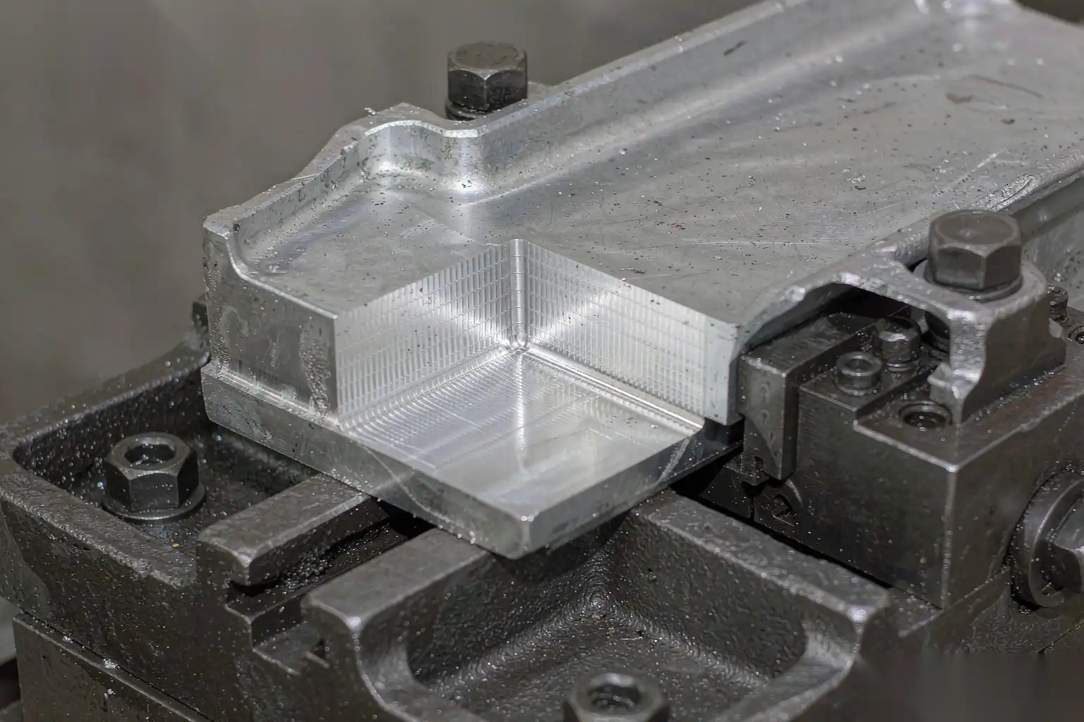
- Clamp on strong sections. Clamping on a thin wall or on a rib deflects the part; the machining then happens on a deflected part and the feature springs out of tolerance when the clamp releases. Clamp over a boss, over a machined pad, or directly over a locator.
- Support against the cut. Thin floors and webs need backing support under the cutting force, otherwise they deflect and the cut leaves a taper. Vacuum or low-melt backing is sometimes worth the cost on large thin parts.
- Handle flash and parting line remnants. Locator surfaces must be clear of flash, or the part sits on the flash and every dimension shifts. Design relief pockets around locators, and specify flash limits on the casting drawing.
- Ejector pin marks. Ejector pins leave raised or depressed marks typically 0.05 to 0.3 mm, depending on pin wear and adjustment. Never locate a datum on an ejector pin mark. Specify on the casting drawing where ejector marks are allowed, and keep them off all datum pads.
- Chip and coolant management. Die cast swarf is fine and abrasive. Fixtures need drainage and chip clearance, or chips pack under the part and it floats.
Parting Line, Ejector Marks, and Gate Location
Three casting features determine most of the difficulty in both machining and finishing, and they should be controlled on the casting drawing rather than discovered later.
- Parting line. Place it away from machined faces and sealing surfaces where possible. Where it must cross a machined face, specify the permissible flash height (typically 0.1 to 0.2 mm) and the permissible mismatch (typically 0.1 to 0.3 mm depending on part size), and add allowance accordingly.
- Ejector pin marks. Specify the permitted depth of raised or depressed marks and their permitted location. Marks on a cosmetic surface become visible after polishing, because polishing does not remove a 0.2 mm depression, it just makes it shiny.
- Gate location. The gate leaves a vestige that must be removed, usually by trimming then grinding. Put the gate on a non-cosmetic, non-datum area, and dimension the allowable gate vestige (typically 0 to 0.5 mm proud, or flush to 0.3 mm below). A gate vestige on a face that the robot then grinds adds a variable amount of stock removal.
How Allowance Choice Changes Deburring and Finishing
The finishing cell is the last operation, and it inherits every upstream decision.
- Cut depth determines burr size. A facing cut that exits an edge at 1.5 mm depth produces a burr roughly two to four times the volume of one produced at 0.5 mm. Burr size drives abrasive consumption, cycle time, and whether a single compliant pass is enough or whether a two-pass sequence is needed.
- Variable stock means variable results. If the casting varies by ±0.4 mm and the machine removes a fixed 1.0 mm, the finished geometry is consistent but the amount of burr formed varies. If the machine instead machines to a fixed dimension, the cut depth varies, and so does the burr. Either way, the finishing cell sees a variable input, which is exactly what force-controlled compliant spindles exist to absorb.
- Exposed porosity is unfixable downstream. No grinding or polishing sequence closes a pore. The only downstream option is to cut deeper, which breaks the dimension, or to scrap. This is why allowance and casting process belong in the same review.
- Polishing amplifies, it does not correct. A polished face shows every subsurface defect as a bright or dark speck. Consistent allowance above the pore layer is the cheapest way to get a high first-pass yield on a cosmetic polished face.
- Edge geometry should be specified. A deburred edge needs a defined break, typically 0.1 to 0.5 mm by 45 degrees or a radius in the same range. Specifying this on the drawing removes an argument and makes the robotic cell programmable to a target.
Getting allowance and datums right is largely a casting-design problem, and aluminum die casting tolerances sets out what capability to expect before you specify stock. On the finishing side, automated edge deburring for production quality covers how cut condition translates into cell design, and aluminum die casting defects and solutions covers the casting defects that allowance is meant to escape.
DZ Machinery builds robotic deburring, grinding and polishing cells for die cast and faucet hardware, and we specify those cells against the actual burr and stock condition of your machined castings. Send us the part drawing with the machining allowance called out, plus a sample before and after machining, and we will give you a cell concept with a realistic cycle time and a defined edge quality target.