Aluminum Die Casting Tolerances: What Is Achievable, What Is Not, and How to Specify
Why Tolerance Specification Matters More Than You Think
The tolerances you put on a drawing drive the cost and capability of the part more than almost any other specification. Tight tolerances:
- Require tighter process control (more inspection, more adjustment)
- Drive up scrap rate when parts fall out of spec
- Increase per-part cycle time
- May require additional operations (machining, grinding, sorting)
Loose tolerances:
- Make assembly fit-up harder
- May affect part function
- Can create assembly problems downstream
- Make cosmetic alignment difficult
The goal is to specify the loosest tolerance that still meets function — the principle of “tolerance as tight as necessary, as loose as possible”. This article covers what is achievable and how to think about it.
Achievable Aluminum Die Casting Tolerances (Standard Practice)
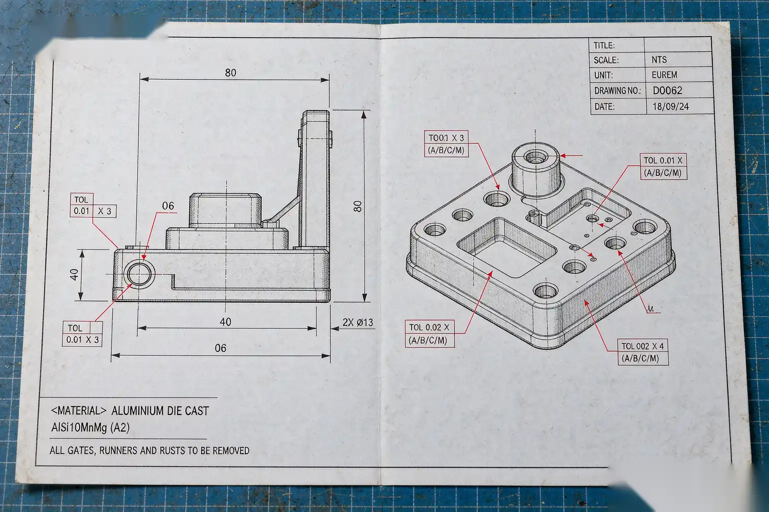
The following tolerances are achievable in production with a well-controlled die casting process using A380 or similar alloys:
| Feature Type | Standard Tolerance | Linear Tolerance (per mm) |
|---|---|---|
| Linear dimension (first 25 mm) | ±0.10 mm | — |
| Linear dimension (25-100 mm) | — | ±0.015 mm per mm |
| Linear dimension (100-500 mm) | — | ±0.010 mm per mm |
| Linear dimension (over 500 mm) | — | ±0.005 mm per mm |
| Flatness | 0.10-0.30 mm per 100 mm | — |
| Roundness | 0.05-0.15 mm | — |
| Concentricity | 0.10-0.20 mm | — |
| Parallelism | 0.10-0.30 mm per 100 mm | — |
| Perpendicularity | 0.10-0.30 mm per 100 mm | — |
| Position | ±0.10 mm typical | — |
| Surface roughness (as-cast) | Ra 3.2-6.3 µm | — |
| Surface roughness (machined) | Ra 0.8-1.6 µm | — |
| Draft angle | ±0.5° | — |
| Wall thickness | ±0.15-0.30 mm (under 3 mm), ±10% (over 3 mm) | — |
These are achievable in production at Cpk > 1.33 for a well-controlled process. The first-pass yield at these tolerances is typically 95-99%.
What Is “Tight” for Aluminum Die Casting
Tighter tolerances require special process control or secondary operations:
- ±0.05 mm linear: achievable with in-die sensing, closed-loop process control, and statistical monitoring. Adds 10-30% to per-part cost.
- ±0.025 mm linear: not achievable in die casting without secondary machining. If you need this, the supplier will machine the critical features after casting.
- ±0.10 mm on first article, ±0.05 mm after machining: typical pattern for parts with both cast and machined features.
What Is Not Achievable
The following tolerances are not achievable in standard die casting:
- Sub-micron tolerances: the die casting process cannot hold this. Use machining or grinding.
- Surface finish below Ra 0.4 µm: the as-cast surface is too rough. Requires machining, polishing, or grinding.
- Optical-quality flatness: not achievable. Requires machining and lapping.
- Sub-millimeter features on tall features: the aspect ratio of tall thin features is limited by die filling.
Where Tolerances Come From
The achievable tolerance on a die cast dimension depends on:
- Dimensional size — larger dimensions have larger absolute tolerance but smaller relative tolerance
- Process control — closed-loop process control, SPC monitoring, automatic adjustment
- Die condition — new die holds tighter than worn die
- Alloy and temperature — different alloys have different shrinkage rates
- Feature location — features near the gate are typically tighter than features far from the gate
- Number of cavities — multi-cavity dies have more variation than single-cavity
- Inspection equipment — the measurement must be more accurate than the tolerance being measured
The single biggest factor is usually process control. A supplier with good SPC will hold tighter tolerances than a supplier with the same die but no monitoring.
How to Specify Tolerances on a Drawing
Best practices:
- Use the loosest tolerance that still meets function. Default to ±0.10 mm or ±0.005 mm per mm for non-critical linear dimensions. Add “REF” or no tolerance to features that do not need it.
- Use GD&T properly. Geometric tolerances (flatness, roundness, perpendicularity) communicate functional intent better than stacked linear tolerances. Apply GD&T to features that mate with other parts.
- Identify critical dimensions explicitly. Tag critical-to-function dimensions with a note like “CRITICAL DIMENSION – 100% INSPECTION” or “CTQ” (critical to quality). This signals to the supplier which features need tighter process control.
- Allow datum structure for inspection. The supplier needs a repeatable reference for measuring critical features. Specify datums and use datum feature symbols.
- State the inspection method. CMM, optical comparator, go/no-go gauge, or visual. Different methods have different accuracy.
- Allow for variation in process. The tolerance window is the full range. If the nominal is 50.00 mm and the tolerance is ±0.10 mm, the supplier must hold between 49.90 and 50.10. The Cpk target should be > 1.33, meaning 4-sigma capability.
Common Tolerance Mistakes on Die Casting Drawings
In our experience, the most common errors:
- Inherited tolerances from a machined part drawing. A machined part may need ±0.025 mm, but the same dimension on a die cast part is much more expensive at that tolerance. Review and relax where possible.
- Tight tolerances on cosmetic non-functional features. A ±0.05 mm tolerance on a cosmetic surface that is hidden inside the assembly adds cost with no benefit.
- Unrealistic flatness on large surfaces. A 200 mm flat surface at 0.05 mm flatness is very difficult in die casting. The die flex, the part cools unevenly, the alloy shrinks differently — all work against this.
- No draft angle specified. Draft angle is critical for ejection and surface quality. Always specify 1-3° draft on all draw surfaces.
- Mixed metric and imperial units. Even with dual dimensioning, suppliers often round in their preferred unit, causing cumulative errors. Pick one and use it consistently.
Process Capability Studies (Cpk)
A proper capability study:
- Collect 30+ consecutive measurements on the critical dimension from a controlled production run
- Calculate the mean and standard deviation
- Calculate Cpk = min(USL – mean, mean – LSL) / (3 * sigma)
- Interpret:
– Cpk > 1.67: excellent, comfortable margin
– Cpk 1.33-1.67: acceptable, normal production
– Cpk 1.00-1.33: marginal, will produce defects
– Cpk < 1.00: not capable, will fail inspection routinely
A capable die casting process runs at Cpk > 1.33 on critical dimensions. A “capable” die casting process on paper is meaningless without a real capability study.
Tolerance Stack-Up Analysis
For assemblies, the cumulative tolerance of stacked features matters. A simple example:
- Part A has a 50.00 ± 0.10 mm hole location
- Part B has a 50.00 ± 0.10 mm peg length
- The stack-up is 100.00 ± 0.20 mm
If the assembly requires the peg in the hole to have 0.50 mm clearance, the stack-up is fine. If the assembly requires 0.10 mm clearance, the parts will interfere 25% of the time.
For critical assemblies, do a tolerance stack-up analysis before finalizing the individual tolerances. This may show that you can loosen the individual tolerances and still meet the assembly requirement.
Cost vs Tolerance Trade-Off
A rough rule of thumb: tightening the average linear tolerance by 50% (e.g., ±0.10 mm to ±0.05 mm) increases per-part cost by 15-30% due to:
- More frequent inspection
- Higher scrap rate
- Slower cycle time (if process control is in-die)
- Additional equipment (CMM, optical comparator)
- More operator skill required
Loosening the average linear tolerance by 50% (e.g., ±0.10 mm to ±0.15 mm) decreases per-part cost by 5-15% but may require design changes to accommodate the looser fit.
Tips for Communicating Tolerances to Your Supplier
- Send the drawing with a tolerance specification note. A single note saying “Standard die casting tolerance per ISO 8062 CT6” or similar gives the supplier a reference for general tolerances.
- Call out critical features separately. Do not bury critical tolerances in fine print. Use a flag, callout, or separate “Critical Dimensions” table.
- Provide inspection requirements. “100% inspection of dimension X” or “Cpk > 1.33 required on dimensions X, Y, Z”.
- Discuss the function. “This dimension controls the clearance for assembly” gives the supplier the information they need to make a sensible decision if the tolerance is borderline.
- Be present at T1 sampling. The first articles are when the discussion of tolerance vs capability happens. If you are not there, the supplier will assume the tolerance is critical and may reject the parts.
What to Ask For in a Supplier Capability Study
A tolerance is a promise; a capability study is the evidence behind it. Before locking tolerances into a production drawing, ask the prospective die caster for capability data — not on your part, which does not exist yet, but on a similar part they currently run: similar alloy, similar size, similar wall section. Request the Cpk on three or four features that resemble your critical dimensions, the measurement method used, and the sample size behind the number. A Cpk quoted from ten parts is a rumor; a Cpk from a hundred parts across several production runs is a promise you can write into a drawing.
Then run the reverse check on yourself. For every tight tolerance on your drawing, ask what function it protects and what breaks if it moves to the next looser standard band. In our experience reviewing customer drawings, roughly a third of sub-±0.05 mm callouts protect nothing in particular — they survive on drawings because someone copied them from the previous part.
DZ Machinery sits downstream of this whole decision chain. Our robotic grinding and polishing cells hold their own tolerances on material removal, but they inherit every tolerance the casting gives them: a part that arrives dimensionally consistent finishes consistently, and a casting with wandering dimensions forces manual touch-up back into the loop. When customers share capability studies with us during design, we can usually show them two or three callouts whose loosening saves finishing cost with zero functional impact — money that goes straight to the bottom line for the life of the program.
FAQ About Aluminum Die Casting Tolerances
What is the standard die casting tolerance grade?
The most common reference standards are ISO 8062 (international) and DIN 1688 (German). For aluminum die casting, CT5-CT7 is the typical capability range. CT6 is the most commonly used for general engineering.
Can aluminum die castings hold the same tolerances as machined parts?
No. Die casting is fundamentally a process with more variation than machining. The achievable tolerance is typically 3-5x larger than machining. If the part design requires machined tolerances, plan for machined features on critical dimensions.
How do tolerances change with part size?
Larger parts have larger absolute tolerances but smaller relative tolerances. A 10 mm feature might hold ±0.10 mm (1% of nominal), while a 100 mm feature holds ±0.15 mm (0.15% of nominal) and a 500 mm feature holds ±0.50 mm (0.10% of nominal).
Should I specify tolerances on cosmetic surfaces?
Generally no, unless the cosmetic surface mates with another part. For pure appearance surfaces, “Class A cosmetic per supplier standard” or similar note is more appropriate than a numerical tolerance.
A Realistic Tolerance Specification
For a typical aluminum die cast part, a reasonable tolerance specification is:
- Linear dimensions < 100 mm: ±0.10 mm
- Linear dimensions 100-300 mm: ±0.20 mm
- Linear dimensions > 300 mm: ±0.30 mm
- Critical features (CTQ): specified explicitly, typically ±0.05 mm with 100% inspection
- Draft angle: 1.5° (range 1-2°)
- Flatness on machined surfaces: 0.10 mm per 100 mm
- Surface roughness on cosmetic surfaces: Ra 1.6 µm (or as specified)
- Standard reference: ISO 8062 CT6 unless otherwise specified
Tighter tolerances should be added only where function demands it. Looser tolerances should be considered wherever possible to reduce cost and scrap.
At DZ Smart Manufacturing, our robotic finishing cells can hold tighter tolerances on the finished surface than manual finishing, particularly for cosmetic and mating features. If you are specifying tolerances for a die cast aluminum part and want feedback on what is realistically achievable in your production environment, our engineering team can review your drawings and suggest tolerance specs that balance function and cost.
See how automated edge deburring improves production quality