Aluminum Die Casting Defects: Identification, Root Causes, and Solutions
Why Die Casting Defects Cost So Much
Aluminum die casting defects fall into two cost categories:
- Visible defects (cold shuts, flow lines, surface blemishes) that fail cosmetic inspection. These are usually caught at the supplier and result in scrap or rework.
- Hidden defects (internal porosity, microcracks) that pass visual inspection but cause field failures. These are far more expensive — warranty claims, customer line shutdowns, recall costs.
A die casting process running at 95% first-pass yield sounds good, but the 5% that escapes often contains the worst field failures. The goal is not just to reduce scrap, but to reduce the variability that lets bad parts through.
The 12 Most Common Aluminum Die Casting Defects

1. Cold Shuts and Cold Laps
Appearance: irregular, often linear surface discontinuities where two metal streams met but did not fuse properly. Look like cracks but are shallow and oxide-filled.
Root causes:
- Melt temperature too low (below 660°C at the die entry point)
- Die temperature too low (below 180°C at start, below 150°C in production)
- Injection speed too slow — metal freezes before filling
- Wall thickness too thin (below 1.0 mm for A380)
- Excessive draft or poor gate design
Solutions:
- Increase melt temperature to 680-700°C
- Increase die temperature with better cooling channel design and pre-heating
- Increase injection speed in the slow-fill to fast-fill transition
- Redesign gate location for better fill pattern
- Add overflow wells at the end of fill path
2. Flow Lines
Appearance: visible bands or streaks on the part surface, parallel to the metal flow direction. Different texture or color from surrounding area.
Root causes:
- Melt temperature variation (cold metal mixing with hotter metal)
- Slow injection speed
- Thin sections causing premature freezing
- Oxide films on the metal surface
Solutions:
- Increase melt and die temperature
- Increase injection speed
- Optimize gate design to fill with single front
- Use vacuum die casting to remove oxides
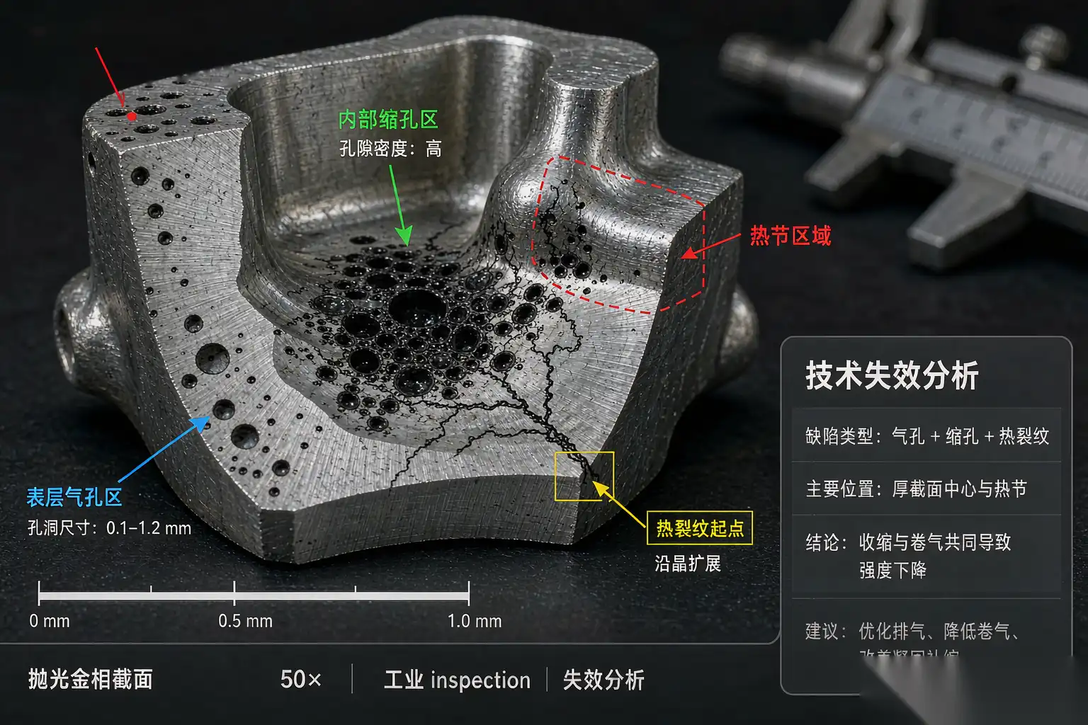
3. Porosity (Gas and Shrinkage)
Appearance: voids inside the part, sometimes visible at the surface as small bumps or revealed by machining or X-ray.
Root causes (gas porosity):
- Air entrapment in the die cavity during injection
- Hydrogen absorption from moisture in the alloy
- Lubricant over-application
- Excessive die spray
- Slow shot speed during the first phase (before high pressure)
Root causes (shrinkage porosity):
- Non-uniform wall thickness — thick sections shrink last and pull voids from surrounding material
- Hot spots in the die from inadequate cooling
- Insufficient intensification pressure
- High pouring temperature
Solutions:
- Use vacuum die casting for gas porosity
- Improve melt degassing (rotary degasser with argon or nitrogen)
- Reduce die spray volume and improve application
- Redesign part for uniform wall thickness
- Add cooling channels at hot spots
- Increase intensification pressure to 80-120 MPa
4. Flash (Burrs)
Appearance: thin metal fin along the parting line, around slides, or through ejector pin holes.
Root causes:
- Insufficient clamping force
- Worn or damaged die surfaces
- Excessive injection pressure
- High melt temperature causing more thermal expansion
- Improper die closing or alignment
Solutions:
- Increase clamping tonnage (rule of thumb: 1 ton per cm² projected area at 30 MPa injection pressure)
- Resurface or replace die at flash locations
- Reduce injection pressure if possible
- Improve die alignment
- Maintain die surface quality
5. Die Soldering
Appearance: localized sticking of aluminum to the die surface, causing pits or rough areas on the part. Often recurs at the same location.
Root causes:
- Iron content in alloy too low (below 0.7% in A380)
- Local hot spots on the die
- Excessive die spray in one area
- Prolonged contact time at high temperature
Solutions:
- Use A380 or alloys with iron content 0.7-1.1%
- Add or improve cooling at the hot spot
- Apply release agent more uniformly
- Refine die steel surface (reduce roughness)
- Apply PVD coating to the die in severe cases
6. Cracks (Hot Tearing)
Appearance: actual fractures, often at hot spots, thick-to-thin transitions, or near the gate. Usually visible immediately after ejection.
Root causes:
- High residual stress from non-uniform cooling
- Ejector pins too small or poorly located
- Excessive alloy content of low-melting elements
- Part design with sharp transitions
Solutions:
- Add cooling at hot spots
- Increase ejector pin area and number
- Reduce silicon and copper content if possible
- Redesign part with more uniform walls and fillets
- Adjust die temperature for more uniform cooling
7. Blisters
Appearance: raised bumps on the part surface, often visible after machining or heat treatment.
Root causes:
- Subsurface gas porosity expanding during heating
- Heat treatment of A380 (T6 causes blistering — alloy is not heat-treatable)
Solutions:
- Reduce gas porosity at the source
- Do not specify T6 heat treatment for A380
- Use vacuum die casting for parts requiring heat treatment
8. Surface Stains and Discoloration
Appearance: brown, gray, or yellow stains on the part surface, often near gates or ejector pins.
Root causes:
- Excessive die spray or wrong die spray dilution
- Contaminated alloy
- Improper handling (bare hands leave oils)
- Oxide formation from slow shot
Solutions:
- Use proper die spray dilution and application
- Verify alloy cleanliness
- Use gloves for handling
- Improve shot profile to reduce oxide formation
9. Dimensional Out-of-Spec
Appearance: critical dimensions outside drawing tolerance.
Root causes:
- Worn or damaged die
- Inconsistent die temperature
- Incorrect shrinkage allowance in die design
- Part design with unrealistic tolerances
- Variation in process parameters (shot speed, pressure, time)
Solutions:
- Maintain and refurbish die
- Improve process control (closed-loop shot monitoring)
- Review dimensional tolerances during DFM
- Implement statistical process control (SPC) on critical dimensions
10. Sticking in Die
Appearance: parts that do not eject cleanly, may tear or have surface damage from forced ejection.
Root causes:
- Insufficient draft angle
- Surface roughness on the die
- Inadequate ejector pin force or location
- Ejector pins too small
Solutions:
- Add draft to all draw surfaces
- Polish die surfaces
- Increase ejector pin area and number
- Add stripper pins for parts with large surface area
11. Welding/Bonding Defects (in assemblies)
Appearance: incomplete weld or weld porosity in welded die cast assemblies.
Root causes:
- Wrong filler alloy
- Contaminated weld area
- Gas porosity at the weld location
- Improper weld parameters
Solutions:
- Use 4043 or 5356 filler for A380
- Clean weld area thoroughly
- Avoid welding in high-porosity zones
- Optimize weld parameters for the joint design
12. Surface Roughness/Orange Peel
Appearance: rough, dimpled surface texture like an orange peel.
Root causes:
- Excessive shot speed
- Alloy contamination
- High iron content causing die soldering tendency
- Die surface wear
Solutions:
- Reduce shot speed
- Use cleaner alloy
- Verify iron content within spec
- Polish or coat die surface
Systematic Defect Diagnosis
When you encounter a new defect, follow this decision tree:
- Is the defect visible at the surface or hidden?
– Surface defects: usually cosmetic, die or process related
– Hidden defects: usually porosity, requires X-ray or CT scan to confirm
- Is the defect at a consistent location or random?
– Consistent location: die-related (wear, damage, cooling)
– Random: process-related (temperature, speed, pressure)
- Is the defect frequency changing over time?
– Increasing: die wear, process drift
– Stable: part design or systematic process issue
– Decreasing: self-corrected (rare)
- What is the alloy and process parameter record?
– Check alloy certification
– Check shot monitoring data
– Check machine parameters (clamp tonnage, shot speed, intensification pressure)
- What is the cost of getting it wrong?
– For critical parts, escalate immediately
– For cosmetic-only parts, accept higher scrap if rework is not economic
A structured approach prevents the most common mistake: fixing the symptom instead of the root cause.
Defect Prevention vs Detection
The economics of die casting defect management:
- Prevention (DFM, die design, process control): $1 invested saves $10 in detection and rework
- Detection (inspection, X-ray, CMM): $1 invested saves $5 in scrap and field failure
- Field failure (warranty, recall): $1 of prevention would have saved $50+
Most die casting operations over-invest in detection (sophisticated inspection equipment) and under-invest in prevention (DFM, process control, operator training). The reverse is more cost-effective.
Building a Defect Review Cadence That Actually Works
Most die casting plants do not lack defect knowledge; they lack defect discipline. The failure pattern is familiar: defects are discussed when a customer complains, actions are assigned, the fire goes out, and the same defect returns two quarters later through a different door. A working cadence fixes this without adding headcount. Weekly, thirty minutes: review the top three defects by cost, not by count, confirm each open corrective action still has an owner and a date, and close anything verified fixed with evidence. Monthly, one hour: trend the Pareto chart against last month and the same month last year, and ask the uncomfortable question — which defect did we accept this month that we would not have accepted last year?
The second discipline is photographing every new defect mode into a shared library with the shot parameters attached. Six months in, that library becomes the plant’s most valuable training asset: a new process engineer can pattern-match a fresh defect against documented history in minutes instead of days.
DZ Machinery sees the downstream end of this discipline in the parts that arrive at our robotic cells. Plants with a real defect cadence feed us consistent castings, and consistent castings let a deburring program hold its cycle time and quality for months without retuning. Plants without it send us surprises. Same robots, same programs — the difference is upstream discipline, and it is free.
FAQ About Aluminum Die Casting Defects
What is the most common aluminum die casting defect?
Porosity (gas and shrinkage combined) accounts for 40-60% of all die casting scrap. Flash and cold shuts together account for another 20-30%. Everything else is less common but tends to be more visible and more expensive to fix.
Can porosity be eliminated completely?
No. Die casting is fundamentally a process that traps some air and creates some shrinkage. Vacuum die casting reduces gas porosity by 80-90% but adds cost. The practical goal is to manage porosity to acceptable levels, not eliminate it.
How do I distinguish gas porosity from shrinkage porosity?
Gas porosity: round, smooth-walled voids, distributed throughout the part, often near the surface. Caused by trapped air or dissolved gas.
Shrinkage porosity: irregular, dendritic voids, located at hot spots or thick sections. Caused by volumetric contraction during solidification.
X-ray or metallographic cross-section is the definitive test. CT scan provides 3D visualization.
Should I accept higher scrap rate or invest in process improvement?
Almost always invest in process improvement. The cost of a good process engineer ($80,000-120,000/year) is recovered by reducing scrap by 1-2% on a $1M annual die casting operation. The math is straightforward.
A Systematic Approach Pays Off
A die casting operation that systematically tracks defects, root causes, and corrective actions will run at 97-99% first-pass yield. A die casting operation that fights defects one at a time will run at 90-95% first-pass yield forever. The difference is process discipline, not technology.
At DZ Smart Manufacturing, our robotic deburring and inspection systems catch surface defects (flash, cold shuts, flow lines) at the next station, before they reach the customer. If you are struggling with high defect rates and want to see how automated post-casting inspection can improve your first-pass yield, our engineering team can review your defect data and suggest a process improvement plan.
See how automated deburring cuts manual grinding defects for castings