Die Casting Pump and Valve Bodies: Porosity, Sealing and Finishing
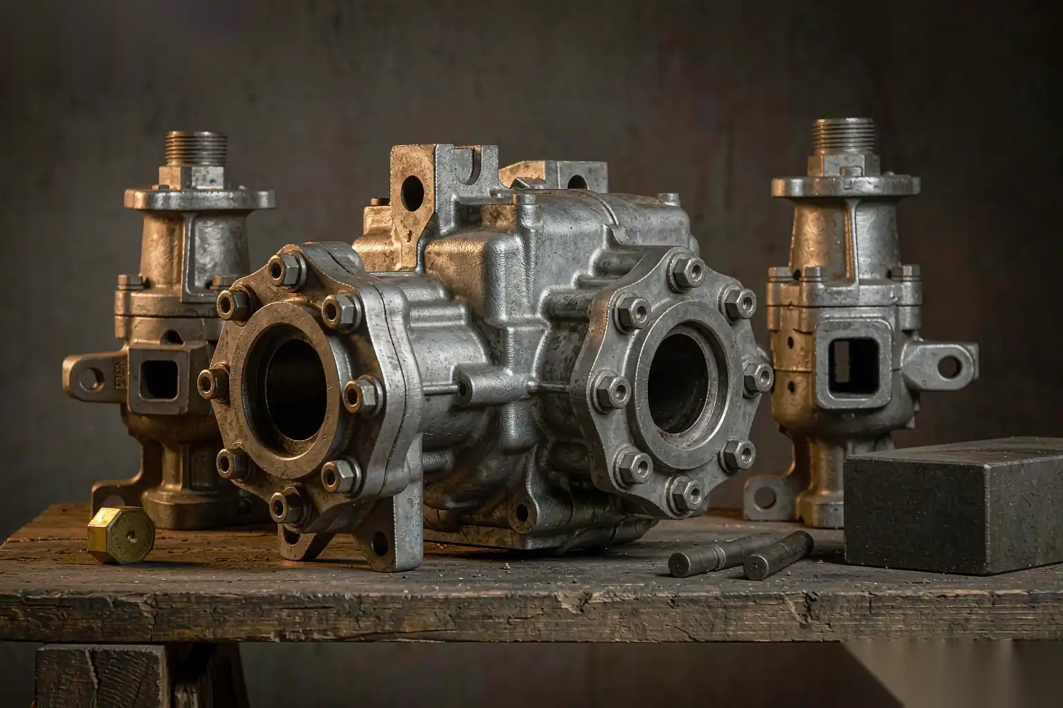
Pump and valve bodies sit at the intersection of two contradictory demands: they must hold internal pressure and resist leakage, yet they are usually made in high volumes where cost per unit decides whether a program survives. Cast iron and sand-cast or gravity-cast aluminum have historically owned this space because engineers trust them to be pressure-tight. High-pressure die casting (HPDC) was treated with suspicion for fluid-carrying parts because the fast fill traps air and produces porosity that opens up during machining of sealing faces. That judgment is now outdated for a large share of pump and valve housings, provided the porosity is controlled at the source and the sealing faces are finished to a repeatable standard. This article walks through the engineering decisions we make when a pump or valve body is moved from sand or gravity casting to die casting, and how the finishing line has to be built so that leakage does not escape the plant.
Why die casting competes for pump and valve housings
The argument for die casting a pump or valve body is rarely about a single property. It is about the total cost and quality package across the annual volume.
- Wall thickness can drop from 4 to 5 mm in a sand casting to 2.5 to 3.5 mm in a die casting for the same pressure rating in aluminum, cutting metal weight by 25 to 40 percent.
- Cycle time moves from minutes per part for sand and gravity casting to 60 to 150 seconds per shot for a typical HPDC housing, enabling volumes of 100,000 to 500,000 parts per year from a single cavity.
- Dimensional scatter on as-cast features is tighter, often plus or minus 0.3 mm on features within 100 mm, versus plus or minus 1.0 mm or worse on sand castings, which means less machining stock and fewer setups.
- The same die casting can be joined to a motor, sensor or manifold with fewer secondary brackets because bosses, ribs and port stubs can be cast in.
The trade-off is porosity. A sand casting is a slow, air-permeable mold where gas escapes; an HPDC tool is a sealed steel cavity filled in 30 to 80 milliseconds, so any air not pushed out becomes a void. For a non-pressure part the void is cosmetic. For a pump body with a 6 to 16 bar working pressure and a valve body with a 10 to 40 bar rating, that void becomes a leak path the moment a drill breaks into it at the sealing face. The rest of this article is about closing that gap.
The decision rule we apply with customers is simple. If the part has a working pressure below about 25 bar, a pressure decay rate that can tolerate 0.5 to 1.0 mL/min, and a machined sealing face that can be localized, die casting is usually the cheaper route. Above roughly 40 bar, or for bodies where the entire internal cavity is a sealing surface, we look harder at vacuum assistance and gate design before committing.
Pressure-tightness requirements and how porosity breaks them
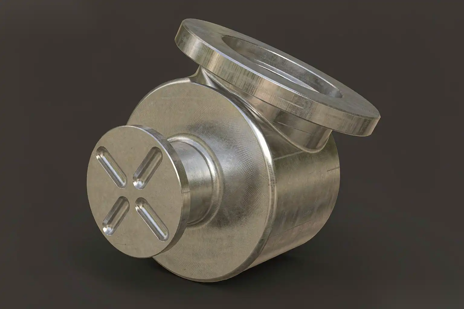
Leakage in a pump or valve body is specified in one of three ways, and they are not interchangeable.
| Spec type | How it is measured | Typical pump/valve target | What kills it |
|---|---|---|---|
| Pressure decay | Drop in pressure over a fixed time at test pressure | 0.5 to 2.0 mbar/min at 1.5x working pressure | Open interconnected porosity at a machined face |
| Mass flow (bubble) | Air volume passing the wall at test pressure | 0.1 to 1.0 sccm | Pinholes through thin sections |
| Helium sniff/accumulation | Tracer gas escaping to a sensor | 1e-5 to 1e-4 mbar·L/s | Microcracks and connected shrinkage |
Porosity is dangerous only when it is connected. A cluster of isolated spherical gas pores 0.2 to 0.5 mm in diameter that never reaches a surface is harmless for sealing. The failure mode is a worm-like, elongated void running from the casting interior to a drilled port seat or a milled flange face. When the cutter breaks through, the part leaks at the test bench even though it looked sound on the outside.
We classify porosity risk by location rather than by total volume:
- Porosity under a machined flange within 3 mm of the cut: high risk, must be suppressed.
- Porosity in a thick boss away from any cut: low risk, acceptable if isolated.
- Porosity intersecting a cored internal channel wall: medium risk, depends on whether the channel is sealed by a gasket or O-ring.
The practical acceptance threshold we use for a machined sealing face is no connected pore larger than 0.3 mm within 2 mm of the finished surface. That is tighter than a typical X-ray class, but it is what the leak test demands. Controlling it starts at the melt and the fill, not at the inspection bench.
Vacuum assistance and melt treatment for sound castings
The two levers that move porosity the most are how much air is left in the cavity at fill and how clean the melt is before it enters the shot sleeve. We cover the cavity-side control in our vacuum die casting guide, and the melt-side control is covered in our aluminum die casting porosity causes and solutions guide.
Vacuum assistance pulls the cavity pressure down to 50 to 150 mbar absolute before the metal front arrives. For a pump body that means:
- Reduction in gas porosity volume fraction from roughly 3 to 6 percent in standard HPDC down to 0.5 to 1.5 percent under vacuum.
- Ability to raise the first-stage plunger speed without folding air, which improves fill of thin port stubs and sharp fillets.
- A measurable drop in leak-test rejects, often from 4 to 8 percent scrap on a tricky valve body to under 1.5 percent.
Melt treatment matters just as much. Hydrogen dissolved in the aluminum expands on solidification and forms round gas pores that later connect to shrinkage. We hold the following on pump and valve programs:
- Degassing to below 0.12 mL/100 g hydrogen equivalent using rotary impeller treatment, verified by a reduced-pressure test sample.
- Filtration through a 20 to 30 ppi ceramic foam filter before the shot sleeve to strip oxides that act as pore nuclei.
- Holding furnace temperature controlled to plus or minus 5 degrees Celsius around 660 to 680 degrees Celsius to limit oxide growth.
A detail engineers underestimate: the shot sleeve itself entrains air if the pour is wrong. We keep the sleeve fill ratio above 60 percent and use a slow first-stage velocity of 0.2 to 0.4 m/s until the sleeve is full, then accelerate. On a 6 kg aluminum pump body this alone cut connected-porosity rejects by about a third in one program we ran.
Machining the sealing faces: datum strategy and stock allowance
A pressure-tight casting is half the battle. The other half is cutting the sealing face so the pore never appears and the gasket seats flat. The datum strategy decides whether your tolerances are real or accidental. Our die casting machining allowance and datum guide goes deeper, but the points that matter for pump and valve bodies are:
- Pick a primary datum from a cast boss or a three-point seat that is reproducible run to run, not from a flash line or a parting-line surface that varies with die wear.
- Machine all sealing faces in a single setup so flatness and perpendicularity are held relative to one reference, avoiding stack-up across fixtures.
- Hold the machined sealing face flatness to 0.05 mm total indicator reading across a 60 to 120 mm diameter seat for soft gaskets, and 0.02 to 0.03 mm for metal-faced or spiral-wound gaskets.
Stock allowance is the balancing act. Too much stock and you pay for cycle time and tool wear; too little and you expose a pore the moment the cutter breaks through. For bodies with vacuum-assisted castings we typically machine:
- Flange faces at 0.4 to 0.6 mm stock per side.
- Port seats at 0.3 to 0.5 mm.
- Bore diameters at 0.5 to 0.8 mm radial.
The number is not fixed. We run a first article, section it, and measure the porosity depth profile, then set the stock so the cut sits at least 0.2 mm above the deepest acceptable pore band. Over a die life of 100,000 to 300,000 shots the die wears and the as-cast surface drifts, so the stock is reviewed at every maintenance interval.
A common failure is machining the port seat from the wrong side of the part, so the cutter approaches the porosity-prone core-print region. We insist on a process drawing that shows the cut direction relative to the gate and vent locations, because that is where the sound metal is.
Surface finish for gasket and seal seating
The finish of the sealing face decides how well a gasket or O-ring does its job, and it is separate from porosity. A face can be pore-free and still leak because it is too rough for the gasket to conform, or too smooth so the gasket creeps.
| Gasket type | Target Ra on machined seat | Typical cutter | Notes |
|---|---|---|---|
| Soft nitrile or EPDM flat gasket | 1.6 to 3.2 micrometer Ra | 45 degree face mill, 4 to 6 flutes | Too smooth below 0.8 micrometer risks gasket slip |
| Spiral-wound with filler | 0.8 to 1.6 micrometer Ra | Fine face mill or ream | Needs flatness tighter than 0.03 mm |
| O-ring in a groove | 0.4 to 1.6 micrometer Ra groove wall | Bored or reamed | Groove bottom finish matters more than flange |
| Metal-to-metal flange | 0.4 to 0.8 micrometer Ra | Single-point or fine mill | Requires lapping on high-pressure lines |
After machining, the deburring step is what protects the seal. A burr left on a port edge will roll into the O-ring groove during assembly and cut the seal. A burr on a milled flange face becomes a leak channel. This is where manual finishing becomes the weak link on a high-volume program: a tired operator misses the same edge that a robot hits every time.
Integrating robotic deburring with leak testing
We treat deburring and leak testing as one cell, not two separate stations, because the handoff between them is where defects are lost. The line we build for a pump or valve body runs:
- Trim and gate removal at the die or by saw.
- CNC machining of faces, bores and ports.
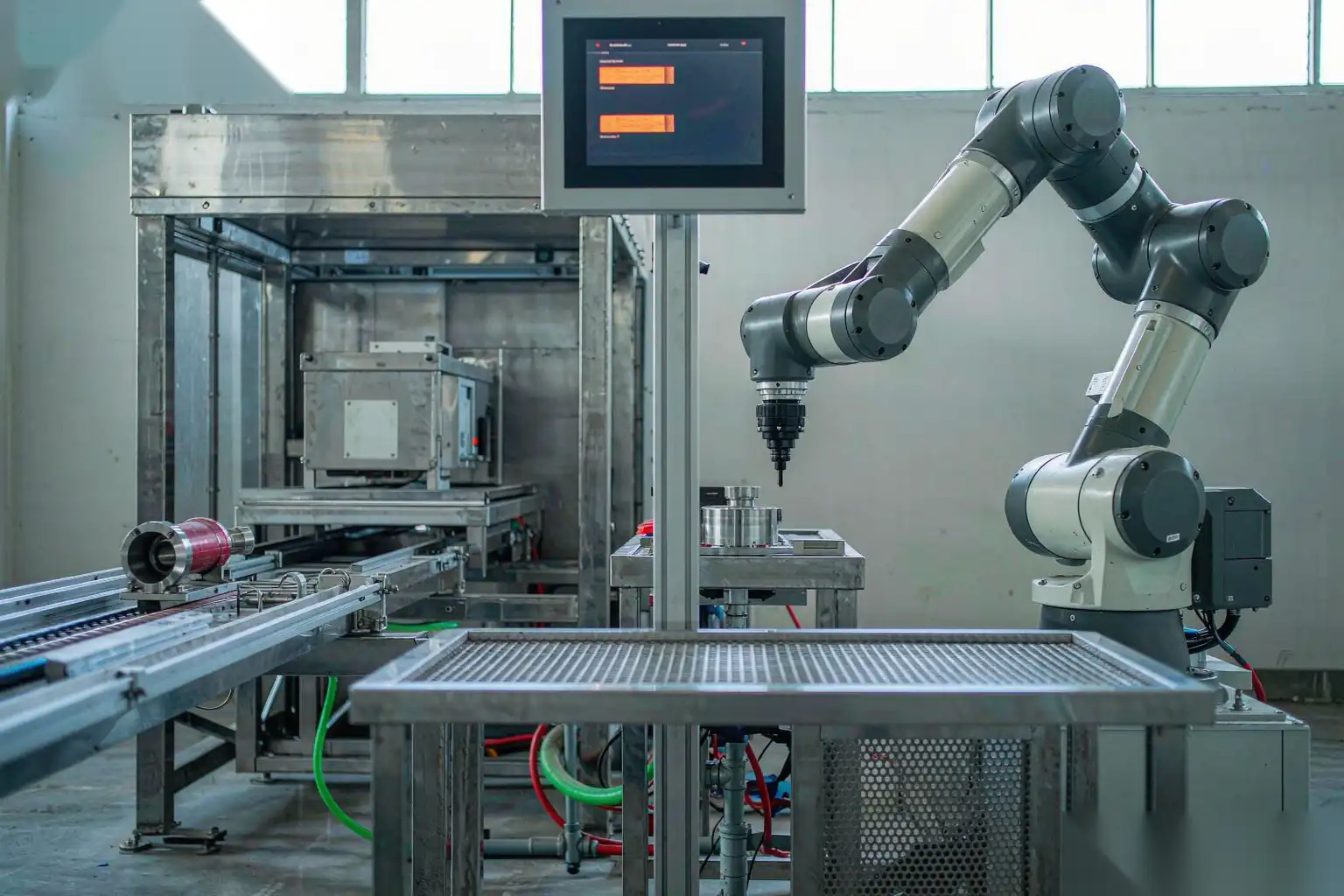
- Robotic deburring of parting-line flash, port edges and cross-drilled hole burrs using a force-controlled floating spindle so the tool follows the as-cast contour rather than cutting a fixed path.
- In-line leak test on a fixture that clamps the same datums used in machining, so a part that passed the cutter is tested in the same reference frame.
- Marking and sort to pass or rework.
The robotic deburring station carries the consistency the seal needs. A force-controlled spindle held at 15 to 40 N of normal force with a 120 to 240 mm/s feed removes flash without gouging the seat. For cross-drilled holes we use a small brush or abrasive filament tool at 2000 to 4000 rpm to break the edge by 0.1 to 0.3 mm, which is enough to protect an O-ring and not enough to change the bore function.
The leak test is run at 1.5 times the working pressure with a 10 to 30 second stabilization and a 20 to 60 second measurement window depending on part volume. A body that fails is diverted, not reworked blind. We capture the pressure-decay curve per part so a drift in the process shows up as a slow change in the average decay rate days before it crosses the reject limit. That trend data is what lets the cell run unattended on a second shift.
A layout for a combined casting-to-leak-test cell
The throughput target sets the cell shape. For a 200,000 parts per year program at 50 seconds cycle per part on a single machining center, you need the deburring and leak test to sit under that time or act in parallel.
| Station | Cycle contribution | Parallelism |
|---|---|---|
| CNC machining | 38 to 55 s | Serial, one center |
| Robotic deburring | 18 to 28 s | Can overlap with next part’s machining if robot cell has a load buffer |
| Leak test | 25 to 50 s | Often paired with a second fixture so test runs while next part deburrs |
| Mark and sort | 4 to 8 s | Inline |
We typically pair one machining center with one six-axis deburring robot and a two-station leak tester, with a small conveyor buffer between. The robot is the flexible element: the same cell can run a pump body in the morning and a valve body in the afternoon by swapping the fixture and the tool program, which is exactly what a jobbing foundry needs. The fixtures are designed for quick change, under 15 minutes including air and I/O confirmation, so changeover does not eat the gain from automation.
Safety and dust are part of the layout, not an afterthought. Deburring aluminum throws fine swarf and the occasional spark, so we enclose the robot with light curtains and run a downdraft dust extraction sized for the metal removal rate. The cell is interlocked so a door open stops the spindle before a hand can reach it.
Acceptance criteria and process monitoring
A pump or valve body is only as good as the data behind it. We lock the program with a first-article report and then monitor the running process against it.
- Dimensional checks on the first three castings per die maintenance cycle, including flatness of the sealing face and bore perpendicularity, on a CMM.
- Porosity checks by X-ray or sectioned sample at the start of each shift for the first week, then weekly once stable, sampling two parts per 1,000.
- Leak-test decay rate recorded per part and plotted as a moving average; an upward drift of more than 20 percent of the limit triggers a melt or process review before scrap accumulates.
- Tool wear tracked by cycle count on the CNC, with insert changes scheduled at 60 to 70 percent of the documented life to keep the seat finish in band.
The biggest source of field leaks we see is not the casting, it is a change made without a record. A die is touched up, the gate is adjusted, the degasser rotor wears, and nobody connects the later rise in leak rejects. The discipline that prevents this is boring but effective: every process change is logged against the part number and the leak-test trend is re-baselined. Over a year that logging typically recovers 1 to 3 percent of units that would otherwise have been scrapped or returned.
For pump and valve bodies, the win from die casting is not a lighter part on a drawing, it is a repeatable part that passes the leak bench at volume. That repeatability is engineered at the melt, held at the machined face, and proven at the in-line leak tester, and a flexible DZ Machinery robotic deburring and leak-test cell is how we build that proof into every shift. If you are weighing a move from sand or gravity casting to die casting for a pressure housing, talk to our engineering team about your part drawings and we will map the porosity, datum and finishing steps before you cut a die.