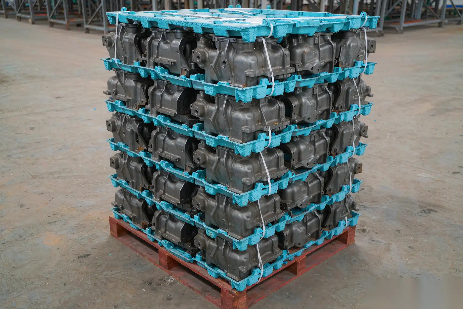
Die Cast Part Packaging: Stopping Damage Between the Finishing Cell and the Customer
A part that passes final inspection and arrives scratched has the same cost as a part that never made it through the cell, plus freight both ways and a customer who now inspects your next shipment harder. In most finishing plants we audit, handling and transit damage accounts for somewhere between 3 and 12 percent of total scrap or return cost, and it is almost always the least engineered part of the process. Grinding parameters get studied for weeks; the box the part goes into gets specified in a sentence.
This article covers the damage mechanisms, the packaging options with realistic cost and protection numbers, the specific rules for polished and plated surfaces, pallet patterns and load unitisation, what to actually specify for drop and vibration testing, and how to write a packaging specification that a supplier will follow without a phone call every month.
Why finished castings get damaged after they leave the cell
The part is at its most vulnerable at the end of the routing. It has been through every value-adding operation, and every subsequent touch carries the full cost of the part.
Four conditions make it worse for castings specifically:
- Weight. Die cast parts are dense relative to their contact area. A 600 g housing landing on a corner concentrates a lot of energy into a small point.
- Sharp geometry. Castings have ribs, bosses and parting line edges that act as punches against neighbouring parts.
- Soft or cosmetic surfaces. Zinc and aluminium scratch at a pencil hardness around 2-3 on the Wolff-Wilborn scale; a polished or plated surface is far more sensitive than the substrate.
- Long, multi-modal transit. Domestic truck, container, cross-dock, and a customer’s own warehouse handling. Each transfer is a new impact event.
Damage is also rarely random. If you log the defect location against the packaging layer and pallet position, the pattern is usually obvious: the bottom two layers, the corners of the pallet, and the top layer under the strap.
Contact and impact damage mechanisms
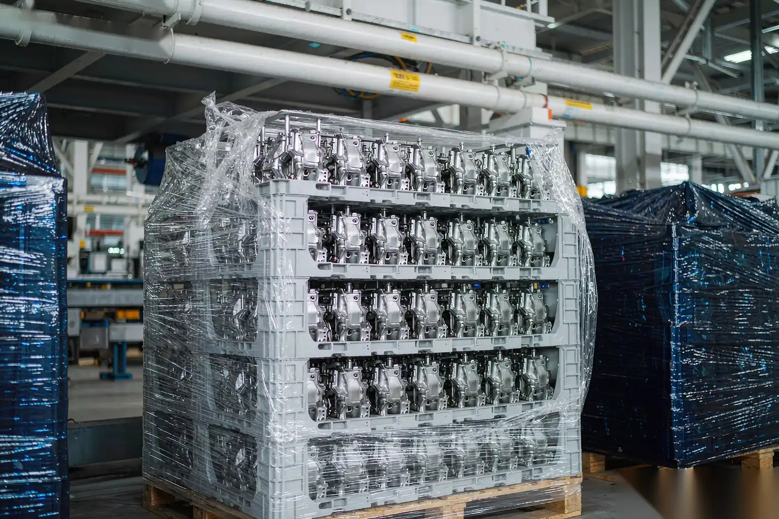
Classify the defect first, then fix the mechanism. Guessing at packing material without identifying the mechanism wastes money.
Abrasion and scuffing
Parts that move against each other or against the container under low load. Signature: fine parallel scratches, directionally consistent, worse on raised features. Cause: insufficient separation, vibration over long distance, or loose parts in a carton. Fix: eliminate relative motion with full separation, or add a low-friction interleaf.
Impact damage
A single event exceeding the local yield or the coating’s adhesion. Signature: a discrete dent, a chipped edge, a crazed or flaked plated area with radial cracking around the strike point. Cause: drops during handling, parts thrown into a tote, a part falling off a conveyor. Fix: increase separation distance and add energy-absorbing material; increase drop height in your test to match reality.
Stacking and compression
Static load over time. Signature: deformation of the lowest layers, crushed corners, cartons bulging, and on thin-wall castings, a gradual bow that shows up as a flatness failure at incoming inspection. Cause: carton compression strength too low for the stack height and storage humidity, or overhang on the pallet. Fix: specify box compression strength with a safety factor and control stack height.
Contact corrosion and staining
Signature: white rust on zinc, grey bloom on aluminium, water spots, or a ring where a wet part touched a dry one. Cause: parts packed warm or wet, humidity trapped in a sealed liner, incompatible materials such as untreated wood or sulphur-bearing paper, or direct contact between dissimilar metals. Fix: dry the part, control the atmosphere, and choose the interleaf chemistry deliberately.
Contamination
Signature: fibre, dust, wood splinters, or black residue in the packing. Cause: corrugated dust, loose-fill that breaks down, open-top totes under a grinding bay. Fix: closed containers, low-lint material, and packing in a clean area physically separated from grinding.
Packaging options compared
There is no universal answer, only a trade between piece cost, cube, labour and protection. The table below reflects typical costs for a part in the 0.3-2.0 kg range, quoted per part or per trip.
| Option | Piece cost (USD) | Protection level | Cube efficiency | Best for | Watch out for |
|---|---|---|---|---|---|
| Bulk in carton, no separation | 0.02-0.10 | Very low | Very high | Rough castings, in-house transfer | Guaranteed scuffing; never for finished parts |
| Corrugated layer pads | 0.05-0.25 | Low to medium | High | Flat parts, forgiving surfaces | Edges unprotected; pads compress over time |
| Paper or foam interleaving sheets | 0.05-0.30 | Medium | Medium | Mixed part families | Labour to place; inconsistent placement |
| Die-cut divider / grid partitions | 0.20-0.80 | Medium to high | Medium | Regular-shaped parts, high volume | Tooling cost 500-3,000; one part per design |
| Thermoformed tray (PET / PP) | 0.35-2.00 | High | Medium to high | Cosmetic and plated parts | Tooling 3,000-15,000; nesting design critical |
| Foam-in-place or die-cut PE / EPE foam | 0.40-2.50 | Very high | Low to medium | Heavy, irregular, fragile parts | Cube, disposal regulation, slow packing |
| Poly bag plus VCI paper | 0.05-0.40 | Medium plus corrosion | High | Non-cosmetic machined castings | Bag scuffing on polished faces; trapped humidity |
| Returnable steel or plastic racking | 1.00-5.00 per trip | Very high | High at volume | Closed-loop, regional customers | Asset tracking, return freight, cleaning, 200-500 trips to pay back |
A useful rule: below about 5,000 parts per year per part number, use a tray or divider you can tool cheaply. Above 50,000 per year to a single customer within 800 km, returnable racking usually beats everything else on total cost, provided you can get the empties back within two weeks. Without a closed loop, returnable packaging becomes an asset write-off.
Protecting polished and plated surfaces
Cosmetic surfaces need different rules from structural ones. The failure is invisible until the customer unwraps the part under their own lighting, at which point it is your problem.
- Never let a cosmetic face touch anything rigid. Contact only on the reverse side or on a non-cosmetic flange. Nesting designs that stack polished face into polished face are the single biggest cause of transit scrap on faucet and hardware parts.
- Use soft, non-abrasive, low-lint contact material. Polyethylene foam, EPE, or a soft non-woven interleaf. Avoid plain corrugated in direct contact: the liner is abrasive and sheds dust.
- Avoid PVC and sulphur-bearing materials against plated and polished surfaces. Plasticisers migrate and chemically etch lacquered brass, chrome and nickel over weeks in a warm container. Use PE or PP, and ask the supplier for a compatibility statement.
- Parts must be dry and cool before wrapping. Pack at ambient, after a verified drying step. A part packed at 50 C in a sealed bag generates condensate overnight and arrives with water staining.
- Handle with clean gloves. Fingerprints on a polished surface etch into the lacquer in a humid container. This is a real reject, and it is avoidable with a glove policy and a simple audit.
- Inspect under the customer’s lighting. Agree the inspection condition: distance, angle, illuminance in lux, and acceptance time in seconds. Most cosmetic disputes are really disputes about inspection conditions, not about the part.
- First-piece and last-piece inspection per shift. Cosmetic damage mechanisms show up within one shift of a change in material or handling, and nobody notices for a month without a deliberate check.
For context on what the customer is entitled to reject, agree the standard in advance; die casting surface finish standards covers how those requirements are normally written and measured.
Load unitisation and pallet patterns
Most transit damage is not caused by a single dramatic drop. It is caused by a pallet that is not a single mass, so every layer moves independently and grinds itself apart over 800 km.
- Pallet standard. Agree one footprint with the customer: 1200 x 1000 mm or 1200 x 800 mm, four-way entry, heat-treated wood (ISPM 15 for export) or plastic for closed loops. Mixed footprints on a container floor guarantee voids and load shift.
- No overhang. Carton or tray footprint should match the pallet within 25 mm. Overhang is the number one cause of crushed corner cartons because the overhanging portion carries no stacking load path.
- Column-stack, not random. Align cartons vertically so the load path goes straight down through the corners. Interlocking brick patterns look stable but transfer load into the carton centre where boards are weakest. If you brick-stack, use a slip sheet every layer.
- Carton strength. Specify the board grade and the box compression test value, not just “corrugated”. For a stack of five layers at 15 kg per carton stored three months, the bottom carton sees roughly 60 kg plus a dynamic factor; specify a compression strength at least 5x the calculated bottom load to allow for humidity, which can cut carton strength by 40-50 percent at 85 percent RH.
- Wrap and strap. Stretch film at 17-23 µm, three to five layers with 50 percent overlap, tensioned so the load is held but cartons are not crushed. For heavy castings, add PET strapping at 12-16 mm with corner protectors; a strap without a corner board cuts into the top cartons and creates a crushed-corner reject on the top layer of every pallet.
- Top cap and corner boards. A cheap top sheet and four corner posts typically cut top-layer damage by more than half.
- Container loading. Fill voids. A 40 mm gap along a container wall turns into a 200 mm shift after a hard brake. Use dunnage bags or timber blocking above 40 mm of void, and strap the last two metres of the load.
Drop test and transport vibration: what to actually specify
Test the pack you ship, not an idealised version of it. Use parts that have been through production, packed by the operators who normally pack them, conditioned to ambient for 24 hours.
A pragmatic test plan for a die cast part in a carton or tray:
- Drop test: ten drops per package, one flat on each face, one on each bottom edge and one on the worst bottom corner. Drop heights scale with packed weight; a common scheme runs from around 800 mm for a package under 10 kg down to 300-450 mm for packages in the 20-40 kg range. Critical orientation is the corner, because that is where the energy concentrates.
- Acceptance after drop: no part-to-part contact evidence, no coating damage under the agreed lighting standard, no carton failure, and the part still meets its dimensional and functional requirements.
- Random vibration: a truck spectrum in the 1-200 Hz range with an overall level of roughly 0.4-0.7 Grms, run for 60-180 minutes per axis. If you cannot get a vibration table, a 400 km road test on a known rough route with three instrumented packages is a legitimate substitute and sometimes more revealing.
- Compression: load the pallet to the maximum planned stack height for 24 hours at 23 C and 50 percent RH, then 24 hours at 40 C and 90 percent RH if the shipment will see a humid climate. Measure bottom-layer deformation.
- Incline and bridge impact: for palletised loads, a 10 degree incline impact test at 1.0-1.6 m/s reproduces most rail and cross-dock events.
Instrument one package with a 3-axis shock logger recording at 500 Hz or better, and set the trigger at 10-15 g. After one round trip you will know the real environment: how many events above 30 g the load saw, at what orientation, and at what time of day. That data ends arguments about who caused the damage and tells you the minimum packaging you actually need, which is usually less than you think in impact and more than you think in separation.
Writing a packaging specification suppliers follow
A packaging spec fails when it describes materials instead of outcomes, or when it is written once and never tied to a purchase order. Write it as a controlled document, referenced by number on the PO, and change it through the same route as any engineering change.
The spec must contain:
- Part identification: part number, revision, and whether the part is cosmetic, plated, machined or rough.
- Quantity per layer, layers per carton, cartons per pallet with a dimensioned drawing of the pack. Drawings stop improvisation far better than words.
- Material specification by grade, not by trade name: board grade and compression strength, foam density in kg/m3, film thickness in µm, VCI type and coverage.
- Separation rule, stated as a requirement: “no part-to-part contact anywhere in the pack” is testable; “wrap carefully” is not.
- Orientation and nesting rule with a sketch showing which face is allowed to contact.
- Dryness and cleanliness requirement: maximum part temperature at packing, no free moisture, no oil transfer onto packing.
- Pallet pattern, wrap, strap and corner protection with quantities and tensions.
- Marking and labelling: part number, quantity, date, batch or shot number for traceability, and any handling symbols such as fragile or this-way-up.
- Test method and acceptance criteria: drop, vibration, compression, and the pass/fail definition, with a re-test trigger.
- Audit method: first-article pack sign-off, plus what happens on a change of material or packer.
Tie the spec to payment reality: if the customer returns damaged goods, the cost lands somewhere. Put that number in the spec review meeting and packaging gets engineered properly the first time.
When the damage is a dimensional or surface defect that may have originated upstream, aluminium die casting defects and solutions is a good starting point for separating a casting problem from a packing problem before you spend money on foam.
Damage investigation: reading the defect
A short diagnostic sequence works in most cases:
- Photograph the defect and the pack in place before unpacking. The position in the pack is the most valuable clue and it is destroyed in ten seconds.
- Map defect locations across the pallet: bottom layer is compression, corners are impact, top layer is strap or handling, uniform distribution is abrasion or corrosion.
- Check the date and batch code against the production and packing records. A single bad day usually means a handling event or a material change, not a packaging design failure.
- Compare the defect orientation to the part’s own geometry. Scratches running in the vibration direction on the contact face mean separation failed, not cushioning.
- Reproduce it. Drop a production-packed carton ten times and see whether you can make the same defect. If you can, the fix is obvious and cheap. If you cannot, suspect the environment or the customer’s own handling.
Packaging checklist for a new part
- Cosmetic classification agreed with the customer in writing, including inspection lighting and acceptance time.
- Damage rate baseline measured for at least one month before changing anything.
- Separation requirement defined and drawn.
- Material grades specified by measurable property, with a second approved source.
- Carton compression strength specified with a safety factor for humidity.
- Pallet pattern, wrap, strap and corner protection documented.
- Drop, vibration and compression test completed on production-packed parts, with results filed.
- One instrumented shipment completed, with shock and humidity data reviewed.
- Labelling and traceability to shot or batch.
- Spec number on the purchase order and a change-control route.
- Annual re-test, or re-test on any material, supplier or customer-handling change.
Add one more item: the finishing cell has to deliver a part that can be packed by the method you specified.
Packaging protects the value that the finishing cell created, and the cell has to deliver a part that can be packed without rework. DZ Machinery builds robotic deburring, grinding and polishing cells for die cast housings, zinc faucet bodies and hardware parts, with fixtures, dust extraction and handling layouts designed so parts leave the cell oriented, dry and repeatable enough for a defined packing method rather than being tipped into a tote. If you are planning a finishing line and want the output to survive the trip, send us the part drawings, annual volume and your current damage rate, and our engineering team will come back with a cell concept, cycle time and yield estimate you can hold us to. For plants comparing sourcing routes, sourcing aluminium die casting from China covers what to check before the shipment leaves.