Shot Blasting Aluminium Die Castings: Media, Surface Profile, and What It Does to Your Grinding Load
Shot blasting sits between the casting machine and the finishing cell, and it is usually specified by whoever happens to own the blast room rather than by whoever has to hit the surface finish at the end of the line. That is how shops end up buying media on price per kilogram and paying for it in belt consumption, rework, and pinholes that only appear after polishing.
This article is written from the finishing end backwards. We run robotic grinding and polishing cells for die cast parts, faucet bodies, and hardware handles, and the condition of the part arriving at the cell decides the number of abrasive steps, the cycle time, and the yield more than any robot parameter does. Blasting is one of the three biggest inputs to that incoming condition, alongside die condition and melt quality.
Covered here: what blasting actually removes, media selection with a comparative table, how grit size and hardness set the surface profile you measure, machine types and their exposure control, parameter windows worth writing into a work instruction, what blasting will never fix, media and dust economics per machine hour, and finally how the blasted surface changes the load on downstream robotic grinding and polishing.
What Blasting Actually Removes, Mechanically
A die casting leaves the machine carrying several things on its surface, and most of them are bad for finishing.
- Die lubricant residue. A carbonaceous-to-waxy film, typically 1 to 5 µm thick, concentrated in areas where the spray pattern pooled or where the die ran hot. This film loads abrasive belts in seconds and causes polishing compounds to skid instead of cut.
- Release agent solids and die build-up transferred to the part. Spot-wise, hard, and often mistaken for casting defects.
- Superficial oxide and handling stain. Days of storage in a humid plant produces a grey bloom that is cosmetic but inconsistent.
- Light flash and parting-line feather. Anything under roughly 0.1 to 0.2 mm tall. Above that, blasting rounds it but does not remove it.
What blasting does mechanically is impact, not cut. Each particle makes a small crater with a raised rim. The visible result is a uniform, isotropic, matte texture with no directionality, which is exactly why it hides die-cast surface defects well and why it photographs consistently for cosmetic parts. The raised crater rims matter downstream: when you polish, those rims are the first material your belt removes, and the first 5 to 15 µm of your polishing allowance disappears into levelling them.
The other mechanical effect nobody puts in the specification is plastic deformation of the surface layer. Blasting cold-works the skin by roughly 50 to 200 µm depth and puts it in compression. That is usually harmless and occasionally useful, but two consequences follow. First, folded metal can bridge over subsurface pores so they disappear at receiving inspection and reappear at the polishing wheel or in the anodising bath. Second, that same folding embeds media fragments in the surface, which for carbon steel shot on aluminium means free iron and rust blooming after plating.
Media Selection
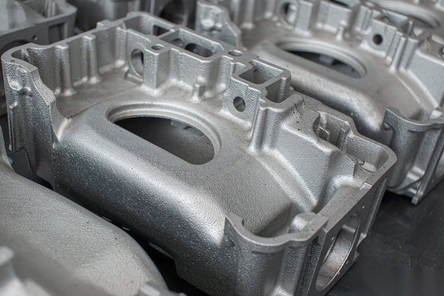
Media choice is a trade between aggressiveness, iron contamination, media life, and operating cost. The table below reflects what we see working in production rather than catalogue marketing.
| Media | Typical size range | Hardness | Typical result on ADC12 | Best used for | Cost per kg (USD, indicative) | Media life / notes |
|---|---|---|---|---|---|---|
| Cast steel shot, spherical | S110–S550 (0.3–1.7 mm) | 40–52 HRC | Cleans and peens, Ra changes little (+0 to +1.5 µm) | Structural parts, brackets, housings before machining | 0.9–1.6 | 500–1500 recycles; iron contamination risk; cheapest per tonne cleaned |
| Steel grit, angular | G25–G80 | 55–64 HRC | Cutting action, Rz can double | Heavy cleaning before painting or coating | 1.0–1.8 | Faster breakdown than shot; aggressive profile |
| Stainless cut wire | 0.3–1.0 mm | 30–40 HRC (conditioned) | Clean, no iron pickup | Parts going to decorative chrome or electroless nickel | 8–14 | 3 to 5 times the life of cast shot; very low dust |
| Aluminium oxide | 24–220 grit | ~2000 HV | Sharp angular profile, highest Rz per pass | Anchor pattern before powder coat or wet paint | 1.2–2.2 | High breakdown rate; high dust; angular profile for adhesion |
| Glass bead | 40–325 mesh | ~48 HRC equivalent | Low cutting, closes texture, satin uniform look | Cosmatte parts before anodising; gentle cleanup | 1.5–2.5 | Fragile at high pressure; excellent cosmetic uniformity |
| Zirconia ceramic bead | 0.1–0.8 mm | ~700 HV | Uniform satin, minimal metal removal | Zinc die castings, thin walls, parts with tight datums | 15–30 | Very long life and very low dust; high purchase price |
The rule we give customers is simple. If the part is going to a robotic polishing cell that has to reach a mirror or satin finish, do not blast it with anything harder than necessary. Media harder than the substrate is what folds the skin and closes pores. For parts going to powder coat, the opposite applies and a deliberate angular anchor profile is a genuine asset.
One special case: carbon steel shot followed by anodising is a recurring source of black speck defects. The embedded iron is not removed by normal alkaline etch in the time available, and every one of those specks becomes a pit. If you already own a steel-shot machine and cannot change media, add a short high-iron-tolerant desmut step or switch the last pass to stainless or ceramic media.
Grit Size, Hardness, and Measured Surface Profile
Surface profile after blasting is governed by particle size, particle hardness relative to the alloy, particle shape, impact velocity, and exposure time. Of those, size and velocity dominate, and velocity is the variable most operators get wrong because “more pressure” is the standard response to a part that looks dirty.
Profile is properly measured as a pair: Ra (arithmetical mean) and Rz or Rmax (peak height above the mean line). Ra alone hides everything that matters for appearance, because two surfaces can have identical Ra and completely different peak populations. A blasted surface and a ground surface both at Ra 2.0 µm look nothing alike. Also consider RSm, the mean peak spacing: blasting produces spacings in the 60 to 200 µm range depending on media size, which is what gives coatings their grip and what makes polishing take an extra step.
Typical measured values on ADC12 die castings, handheld roughness tester, 0.8 mm cut-off, five readings averaged:
| Condition | Ra (µm) | Rz (µm) | RSm (µm) |
|---|---|---|---|
| As cast, good die condition | 1.2–3.2 | 8–18 | — |
| As cast, eroded or soldered die areas | 4.0–8.0 | 25–45 | — |
| Steel shot S230, 65 m/s tip speed, 45 s | 3.0–5.0 | 18–30 | 120–200 |
| Aluminium oxide 60 grit, 5.5 bar air blast | 5.0–9.0 | 30–55 | 80–150 |
| Aluminium oxide 120 grit, 4.5 bar | 3.0–5.5 | 20–35 | 60–120 |
| Glass bead 100/170 mesh, 4.0 bar | 1.8–3.2 | 12–22 | 90–160 |
| Glass bead 200 mesh, 3.0 bar | 1.2–2.0 | 8–14 | 60–110 |
| Ceramic bead 0.3 mm, 4.0 bar | 1.5–2.8 | 10–18 | 70–130 |
Two practical implications for the finishing cell. First, an aluminium oxide 60 grit blast puts you roughly 4 to 6 µm above as-cast Ra, which means your first abrasive step has to remove that difference before it starts doing useful work. On a faucet body that is typically one extra belt pass, 8 to 15 seconds of robot time, and measurably shorter life on the coarse belt. Second, variability matters more than average. A batch where Ra ranges from 3 to 9 µm gives a force-controlled robot a moving target; the float spindle follows the contour, low spots get over-polished, and the cell yield drops. We would rather receive Ra 4 µm ±1 than Ra 3 µm ±4.
Dimensional effect is small but real. Blasting removes 5 to 30 µm of aluminium, occasionally more at corners where exposure concentrates. For casting tolerances that are already generous this is irrelevant, but if you have machined datums, sealing faces, or press-fit bores already in the part, mask them or blast before machining. See aluminum die casting tolerances guide for how that interacts with the datum scheme.
Equipment Types and How Each Controls Exposure
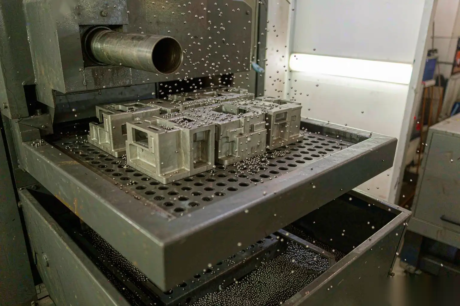
Exposure consistency is the whole point of machine selection. The three families used for die castings differ almost entirely in how evenly they present every part and every face to the media stream.
| Machine type | How parts are presented | Typical batch or rate | Exposure consistency | Strengths | Weaknesses |
|---|---|---|---|---|---|
| Tumblast (barrel batch) | Parts tumble in a rotating rubber or steel belt mill; wheel throws media into the tumbling mass | 100–400 kg per batch, 4–10 min cycle | Poor to moderate. Random part-on-part contact; shadowed faces get less exposure | Lowest capital cost, simple, high throughput per dollar | Part-on-part damage on cosmetic faces; thin sections can deform; not suitable for polished surfaces |
| Spinner hanger | Parts hung on hooks or trees which rotate and orbit past one or more wheels | 1–6 fixtures per cycle, 60–240 s per hook | Moderate to good. No part-to-part contact if racked properly; each fixture sees repeatable exposure | Good for medium parts, machined-critical parts, zinc handles | Labour-intensive loading; fixture design matters; hook contact marks |
| Continuous belt / wire mesh belt | Single layer of parts passes under multiple wheels at fixed belt speed | 0.8–3.0 m/min belt speed; 20–60 s under each head | Best. Fixed distance, fixed angle, fixed time for every part | Highest consistency, easy to integrate into a line, consistent for automation | Requires stable geometry parts; needs multiple heads for complex shapes |
| Monorail continuous / rotary table | Parts on rotating satellites pass through fixed wheel stations | 2–8 satellites, indexing every 20–60 s | Good, especially with indexed satellites | Versatile; can combine blasting with loading robot cell | Higher capital; bigger footprint |
For a part that will face robot or hand polishing afterwards, we push customers toward the continuous belt or rotary table designs. The reason is not throughput, it is variance. An automated finishing cell can be programmed to tolerate a predictable input; it cannot be programmed to tolerate a random one, and the cost of a variable input shows up as either rework or an over-designed process with too many passes.
For low volume or job-shop work where a tumblast already exists, the saving grace is simple process discipline: fixed batch weight, fixed blast time, fixed media top-up schedule, and never filling above 60 to 70 percent of rated volume. Over-filling a tumblast is the single most common cause of both poor cleaning and part damage.
Parameter Windows Worth Putting in a Work Instruction
Every one of these should be a number with a tolerance, not a habit.
- Wheel tip speed. Typical centrifugal wheels run 55 to 85 m/s tip speed. For a 380 mm diameter wheel that is roughly 2,760 to 4,270 rpm; most machines sit at 2,250 or 3,000 rpm, giving about 45 to 60 m/s on that diameter. Media wear rises with approximately the square to cube of impact velocity, so a machine running at 80 m/s when 60 m/s would clean adequately is burning two to three times the media. Run the lowest speed that achieves coverage.
- Media flow rate. Roughly 8 to 12 kg per minute of steel media per kW of wheel power. An 11 kW wheel runs 90 to 130 kg/min; a 15 kW wheel 130 to 180 kg/min. Aluminium oxide runs lower, typically 40 to 90 kg/min, because the higher mass flow simply destroys media. Low flow relative to that window means long exposure times and poor coverage; high flow wastes media and overloads the separator.
- Exposure time. Spinner hanger: 45 to 180 s depending on section complexity. Continuous belt: 20 to 50 s per head, often with two heads at opposing angles to cover shadowed geometry. Tumblast: 4 to 8 min, and remember that only the parts at the top of the tumbling mass are actually being hit at any instant.
- Air blast pressure (where used instead of wheels). 4 to 7 bar at the nozzle, never above what the cleaning task needs. A 6 mm nozzle at 6 bar consumes roughly 2.5 m³/min of free air, which is 15 to 18 kW of compressor input. Every bar you can drop saves roughly 10 percent of that.
- Nozzle distance and angle. 100 to 250 mm standoff, 45 to 90 degrees impingement. Beyond 300 mm the stream spreads and cleaning collapses; below 100 mm you get localised over-blast and visible swirl on cosmetic faces.
- Separator and media conditioning. Keep the operating mix within specification. For steel shot, target more than 80 percent of the working mix within one screen size of nominal. Broken media and fines in the mix are the cause of most “the machine suddenly stopped cleaning” complaints. Check the mix weekly by screening.
What Blasting Fixes and What It Never Will
Be explicit about this in the process documentation, because it is where most quality disputes between casting and finishing departments start.
Blasting genuinely fixes:
- Die lubricant residue and transfer build-up on the casting surface.
- Uniform cosmetic texture, which makes die-cast flow lines and light cold-flow marks much less visible.
- Light flash up to about 0.1 to 0.2 mm in height, where the feather is thin enough to be knocked off rather than bent over.
- Coating adhesion, by producing a clean, active surface with a defined anchor profile.
Blasting does not fix, and pretending otherwise costs money:
- Parting line mismatch. Typical die mismatch is 0.05 to 0.25 mm of step height. Blasting rounds the edge, which reduces its visual sharpness under raking light, but the step is still there and still needs grinding. This is the single biggest misconception about blasting.
- Heavy flash above about 0.2 mm. It gets folded into a ridge and can end up harder to remove than before.
- Sink marks and shrink depressions. Blasting cannot add metal.
- Subsurface porosity. Blasting can hide it temporarily by folding the skin over the pore. It reappears at polishing, at anodising, in a leak test, or in service. Our view is that blasting before leak testing is a bad practice for anything pressure-tight. See aluminum die casting porosity causes solutions for the upstream causes.
- Dimensional defects. Nothing about blasting is dimensionally corrective.
The acceptance criterion we recommend: define the incoming part in terms of defect dimensions, not appearance. If the maximum acceptable parting-line step after grinding is 0.05 mm, write that into both the trim die maintenance schedule and the blast specification, and measure it with a dial indicator or a profilometer trace rather than by eye. The die casting surface finish standards article covers how to write those callouts so that they survive contact with a supplier.
Media Consumption, Dust Load, and Cost per Hour
Blasting economics are driven less by machine purchase price than by media consumption and waste disposal. Indicative figures for a medium duty wheel machine running one shift:
| Item | Steel shot | Aluminium oxide | Glass bead | Ceramic bead |
|---|---|---|---|---|
| Consumption per operating hour | 3–8 kg | 25–60 kg | 15–35 kg | 0.5–2 kg |
| Consumption per tonne of parts cleaned | 2–6 kg | 20–45 kg | 12–30 kg | 0.3–1.2 kg |
| Fines and dust to collector per hour | 1–3 kg | 20–40 kg | 10–25 kg | 0.3–1 kg |
| Disposal comments | Recyclable or general waste depending on local rules | Usually general industrial waste | Glass fines, check local rules | Very low volume but expensive per kg |
A useful comparison is cost per tonne of parts rather than cost per kilogram of media. Steel shot at 1.2 USD/kg consumed at 4 kg per tonne of castings is roughly 5 USD per tonne. Aluminium oxide at 1.6 USD/kg consumed at 30 kg per tonne is roughly 48 USD per tonne, ten times higher. Ceramic at 20 USD/kg consumed at 0.8 kg per tonne is around 16 USD per tonne, and usually delivers lower downstream cost because the profile is gentler and more consistent.
Two safety items belong here because they are regularly missed in aluminium plants. Aluminium fines below about 500 µm are combustible dust with Kst values that can exceed 300 bar·m/s, putting them in the higher explosion severity classes. That means dry collectors need deflagration venting or suppression, duct velocities need to keep dust in suspension (typically 20 to 25 m/s minimum), and housekeeping has a hard limit rather than a suggestion. Wet collectors are an option but create a sludge disposal problem and can generate hydrogen from the aluminium-water reaction if the sludge is allowed to sit warm. Design the collector before installing the machine, not after.
Dust also affects downstream quality directly. Parts that leave the blast machine and sit for hours collect media fines and dust on their surface, and that contamination goes straight into the first abrasive belt. Keep blasted parts covered, and time-box the interval between blasting and finishing to one shift.
How the Blasted Surface Changes Your Robotic Grinding and Polishing Load
This is the section most blasting specifications skip, and it is where the money is.
A robotic cell with a force-controlled float spindle depends on predictable contact mechanics. Everything blasting does to the surface changes those mechanics in three ways.
- Removal volume. The robot has to take the part from the incoming Ra/Rz down to what the first polisher expects. If blasting adds 5 µm of Ra and 30 µm of Rz, that is 5 to 30 µm that has to come off the whole cosmetic face before the surface is level. On a 200 cm² cosmetic face that is roughly 0.4 to 0.6 cm³ of aluminium per part, which sounds trivial until you multiply by a shift and price it in belt life.
- Abrasive loading. Removing die lube before finishing is unambiguously good: belts last 20 to 40 percent longer and polish compounds behave consistently. Blasting that leaves embedded media instead achieves the opposite, because hard fragments act as a contaminant between the abrasive and the work.
- Process stability. Uniform blasted texture actually improves force-control stability once the initial passes are done, because the coefficient of friction is constant across the part. Uneven blasting, especially localised over-blast at corners near nozzles, produces hard spots that read as geometry variation to the force loop.
The following table summarises what we typically observe on a mid-size faucet body going through a six-step robot polishing line.
| Incoming condition | Extra roughing passes required | Added cell time per part | Coarse belt life, parts per belt | First-pass yield to mirror finish |
|---|---|---|---|---|
| As cast, clean die, no blast | 0 | baseline | 900–1200 | 96–98 percent |
| Light glass bead, Ra 2.0–3.0 | 0 | +3 to 6 s | 1200–1600 | 96–98 percent |
| Fine steel shot S170–S230 | 0 to 1 | +6 to 12 s | 1000–1300 | 94–97 percent |
| Aluminium oxide 120 grit | 1 | +10 to 18 s | 700–950 | 92–96 percent |
| Aluminium oxide 60 grit, heavy | 2 | +20 to 35 s | 450–700 | 85–93 percent, high pinhole rework |
The takeaway is not “never blast”. It is that the blast specification should be set jointly with whoever owns the finishing yield. For cosmetic zinc handles and faucet bodies going to mirror Polish, our recommendation is normally light ceramic or fine glass bead in the Ra 1.5 to 3.0 window, or nothing at all if the casting is clean and the die is in good condition. Where blasting is needed to hide flow lines prior to powder coating, use the most aggressive media that still leaves enough material for subsequent machining, and remember blasting is not a substitute for grinding the parting line.
DZ Machinery builds robotic deburring, grinding and polishing cells with force-controlled float spindles, multi-station indexing tables and integrated dust extraction, and we routinely run incoming parts through trials to set exactly these windows against real cycle times. If you want your blast specification reconciled with your polishing cell rather than optimised in isolation, send us the part drawings and the incoming roughness data.