Aluminum Die Casting Process Steps: From Ingot to Finished Casting
A die casting cycle looks like one motion and is actually about a dozen controlled events, each with a window that has to be defended. When a part fails, the cause is almost always a parameter that sat at the edge of its window for a few thousand shots before somebody noticed. This is the sequence we walk through with customers when we are sizing the equipment downstream of the machine, because the state the casting leaves the die in determines what the saws, CNC cells, grinders and polishers have to deal with.
Step 1: Melting and melt treatment
The cycle nominally starts at the melting furnace, and a lot of downstream problems are decided here.
- Charge make-up. Typical production charges are a mix of primary ingot and returned internal scrap: runners, biscuits, overflows and rejected castings. A common ratio is 60-70% ingot to 30-40% returns, though some plants run higher returns. Returns must be segregated by alloy and free of oil, water and machining chips.
- Melting furnace. Gas or electric crucible/reverberatory, melting at 700-750 °C. Going above roughly 760 °C accelerates hydrogen pickup and iron dissolution from the crucible and the tooling.
- Holding furnace. Metal is transferred to a holding furnace at 640-680 °C and dosed from there. Holding above about 720 °C for extended periods is where you buy porosity and die soldering together.
- Degassing. Rotary degassing with nitrogen or argon, 10-20 minutes per treatment, rotor speed 300-500 rpm. The goal is dissolved hydrogen below roughly 0.15 ml/100 g, verified by a reduced pressure test with a density index target of ≤ 3%, or ≤ 2% for leak-critical parts.
- Fluxing and dross removal. Dross is skimmed every 2-4 hours and before any alloy change. Residual flux and dross inclusions become leak paths and machining defects, and they are a corrosion initiation site if they reach the surface.
- Melt loss. Expect 2-5% of charged weight as dross and oxidation loss. A sudden change in that number usually means temperature control or charge quality has moved.
Step 2: Dosing and transfer
An automatic ladle or a dosing furnace transfers a measured shot weight into the cold chamber. The shot weight includes the casting, the runners and gates, the overflows, and the biscuit; process yield on the useful casting is typically 50-75% of the total shot, with the remainder recycled.
Points that matter here:
- Repeatability. Shot weight variation of more than about ±1.5% changes the biscuit thickness, which changes the pressure transmission during intensification.
- Transfer temperature loss. Metal loses 20-40 °C between the holding furnace and the shot sleeve depending on ladle design and transfer time. Control the time, not just the furnace setpoint.
- Sleeve fill ratio. The shot sleeve should be filled to roughly 40-60% at the start of injection. Fill it too full and you cannot run a proper slow shot wave; fill it too little and you trap air.
Step 3: The injection curve
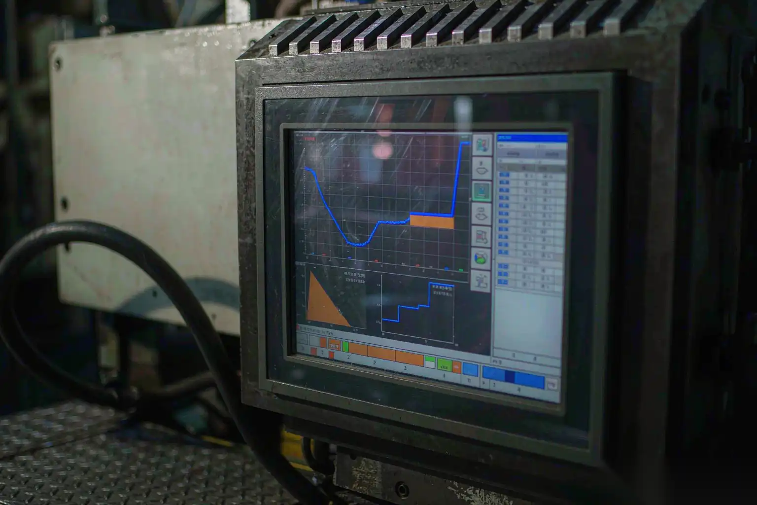
This is the heart of the process. The plunger moves through three distinct phases, and each has its own parameter window.
| Phase | Purpose | Typical window | What goes wrong outside it |
|---|---|---|---|
| Slow shot | Push metal forward as a stable wave, expel sleeve air through the vent | Plunger velocity 0.15-0.60 m/s; acceleration controlled | Too fast: wave breaks, air entrained, gas porosity. Too slow: early solidification, cold shuts, fill marks |
| Fast shot / switchover | Fill the cavity before the metal freezes | Switchover at 60-85% of stroke; gate velocity 30-60 m/s, up to 80-100 m/s on thin walls; fill time 20-80 ms, 10-40 ms for thin wall | Late switchover: misruns and cold shuts. Excessive velocity: die erosion, flash, air entrapment at the last fill point |
| Intensification | Compensate shrinkage while the gate freezes | Pressure 60-100 MPa (600-1000 bar); delay 20-50 ms; rise time under 30 ms | Low pressure or long delay: shrinkage porosity in heavy sections. Too high: flash and die deflection |
| Dwell / holding | Hold pressure until the gate is frozen | 1-8 s depending on section thickness | Too short: back-feed of shrinkage. Too long: no benefit, slower cycle |
| Die closed / solidification | Extract heat at a controlled rate | Die surface 180-250 °C; cycle 30-120 s | Cold die: cold shuts, fill marks. Hot die: soldering, longer cycle, blisters |
Two parameters deserve special attention because they are the ones most often wrong in a running process.
Switchover position. The point at which the machine changes from slow to fast injection is set as a percentage of stroke or an absolute plunger position. If it is late, the fast shot begins with the cavity partly filled and the wave already broken; you get cold shuts and scattered gas porosity. If it is early, the metal jets into the cavity and entrains air. On a stable program this value should be recorded and alarmed shot by shot.
Intensification delay. The time between the end of fill and full pressure. The gate has to still be open. A delay beyond roughly 50 ms on a thin-wall part means you are intensifying into a frozen gate and the heavy section gets nothing but shrinkage.
Also worth logging per shot: the actual slow shot velocity profile, the fast shot velocity at the gate, the peak metal pressure, and the cycle time. Machines give you this; most plants do not trend it. Trending it is the cheapest predictive maintenance available in the cell.
Step 4: Die lubrication and thermal balance
Before each shot the die faces receive a water-based release agent, applied by a reciprocating spray head or by fixed manifolds.
- Dilution. Typical 1:50 to 1:200 concentrate to water, adjusted by part complexity and die temperature. Over-concentrated release agent builds up in vents and on cores, and the residue contributes to surface staining and to pre-treatment problems if the part is coated later.
- Spray duration. 0.5-3 seconds, plus blow-off. Long spray times cool the die locally and cause cold shuts; short ones leave the die hot and invite soldering.
- Die temperature control. Internal cooling lines, plus spot cooling on heavy cores. Target 180-250 °C surface, measured at the start of the shift and after any stoppage.
- Warm-up. The die needs 20-60 cycles to reach thermal steady state depending on mass. Parts made before steady state are scrap, and a first article taken from shot three is not a first article.
Step 5: Solidification, opening and ejection
After the dwell, the machine opens and ejectors push the casting off the fixed or moving half.
- Ejection balance. Ejector pins are placed to push the casting off square. Uneven ejection bends thin walls and cracks bosses; the classic symptom is a part that is in tolerance hot and out of tolerance after it cools.
- Ejector stroke and timing. Parts are usually ejected at 300-450 °C, hot enough to be ductile and cool enough to hold shape.
- Take-out. Manual or robot take-out to a quench tank, a conveyor, or directly to the trim die. Robot take-out gives a consistent quench delay, which matters if you are controlling mechanical properties or distortion.
- Biscuit and shot monitoring. The biscuit should be 10-20 mm. A thinning biscuit is a sign that the shot weight or the sleeve fill is drifting.
Step 6: Trimming, runner removal and quenching
The as-shot cluster goes to a trim die in a hydraulic press, typically 20-100 tonnes depending on the projected area of the trim.
- Trim die. Shears the runner, gates and overflows off in one stroke. Trim die clearance is normally 0.05-0.15 mm per side on the cutting edge; dull or badly set trim dies leave a raised burr that has to be removed later and is a common source of extra work downstream.
- Gate remnants. A properly designed gate leaves 0.2-1.0 mm of remnant on most parts. If the gate is thick or the trim die is worn, you get 2-4 mm and the grinding stage grows accordingly.
- Quenching. Water or air, usually to below 100 °C within 30-120 seconds. Water quench freezes the as-cast structure and is used when the part goes to machining or when a subsequent heat treatment is planned. Air cooling is gentler and produces less distortion.
- Ageing. Castings continue to change for roughly 7-30 days after casting as precipitation proceeds. If a dimension is critical and machined, either allow the natural ageing window or specify a stabilization treatment.
Step 7: Secondary operations
For most commercial parts, this is where the money is. The casting operation may be 40-60% of the delivered cost on a cosmetic part, and the secondary operations are where labour concentrates.
| Operation | Typical parameters | Notes for the process plan |
|---|---|---|
| Band sawing | Carbide or bi-metal blade, 25-60 m/min | Used for large runners and sprues, and for low-pressure and gravity cast parts with heavy feeders |
| CNC machining | 3-5 axis, 6,000-18,000 rpm | Faces, bores, threads. Stock allowance on as-cast surfaces typically 0.5-1.5 mm |
| Deburring | Belt 80-180 grit, or spindle with carbide burr | Removes parting line witness and trim burr. Allowance 0.1-0.5 mm typical |
| Grinding | Flap wheel or belt 60-120 grit | Gate remnant leveling and blend-out. Removal 0.3-2.0 mm |
| Polishing | Belt 180-600, then sisal and cloth with compound | Cosmetic surfaces, faucet bodies, handles, lock plates. Multi-station, compound feed |
| Shot blasting | Steel shot 0.2-0.6 mm, or glass bead | Uniform matte surface, removes parting line marks before coating |
| Leak test | Pressure decay, 0.5-6 bar | 100% on pressure boundary parts |
| Impregnation | Vacuum/pressure resin, cure 85-95 °C | Salvage route for microporosity; should be a fallback, not a process step |
| Coating | Powder, e-coat, anodize or conversion | Needs a controlled pre-treatment sequence; see our aluminum die casting finishing options overview |
The sequence matters. Deburr before grinding, grind before polishing, polish after any machining that breaks the surface, and always leak test after machining rather than before, because a machining operation can open a pore that was sealed by as-cast skin.
Details of the deburring and polishing route options, and what each costs in cycle time, are covered in how to deburr aluminum die castings with automation.
Step 8: Inspection and pack
- First piece layout on every setup, full CMM on at least one piece per cavity.
- In-process SPC on key characteristics, typically 5 pieces every 1-2 hours per cavity, with Cpk ≥ 1.33 on machined and assembly-critical dimensions.
- Porosity sampling by X-ray against a reference standard, with acceptance zoned by function, and AQL 0.65-1.0 in critical zones.
- Leak testing per the specified decay limit, on 100% of pressure boundary parts.
- Cosmetic inspection against signed limit samples under defined lighting, 800-1000 lux at a stated viewing distance.
- Pack to the agreed configuration, with cavity and lot traceability marked.
The aluminum die casting tolerances guide defines what to expect as-cast before you add machining to hold a dimension, which is the number that should drive the inspection list above.
Where automation changes the economics
Steps 1 through 5 are machine-controlled and reasonably repeatable. Steps 6 through 8 are where manual work enters, and where the variation that a control plan cannot absorb is created. Three failure patterns show up repeatedly:
- Burr height follows the operator, not the part. A hand-held grinder removes what the operator thinks is enough. Two operators produce two different edge conditions, and the cosmetic reject rate follows the shift roster.
- Polishing is the bottleneck. A faucet body or a lock plate may need four to seven polishing stations with belt, sisal and cloth. Manual polishing is also the hardest station to staff and the one with the highest reported injury and dust exposure.
- Gate remnant variation propagates. If the trim die is allowed to wear, the grinder has to remove 2 mm where it was designed to remove 0.5 mm, and cycle time triples.
DZ Machinery builds the equipment for these stages. Our 6-axis robotic deburring and grinding cells use force-controlled floating spindles, so the contact force is a set parameter rather than a human judgement, with pneumatic or compliant belt heads, automatic tool change and multi-station rotary tables for loading during the cycle. Our polishing cells run belt, sisal and cloth stations in sequence with automatic compound feed, which is what makes a repeatable cosmetic finish achievable on faucet bodies, zinc and aluminum handles, and lock plates. We also integrate the whole line around them: core shooting, low-pressure or gravity casting, band sawing of the runner, CNC, robotic grinding, automatic polishing and inspection, with the fixtures, dust extraction and guarding designed in.
The practical next step is a cycle time study. Send us the part model, the material, the as-cast burr specification or a sample part, and your target output. We will return a station count, a cycle time per station, the abrasive consumable estimate and the dust extraction requirement, and we will tell you honestly where a manual station is still the right answer.