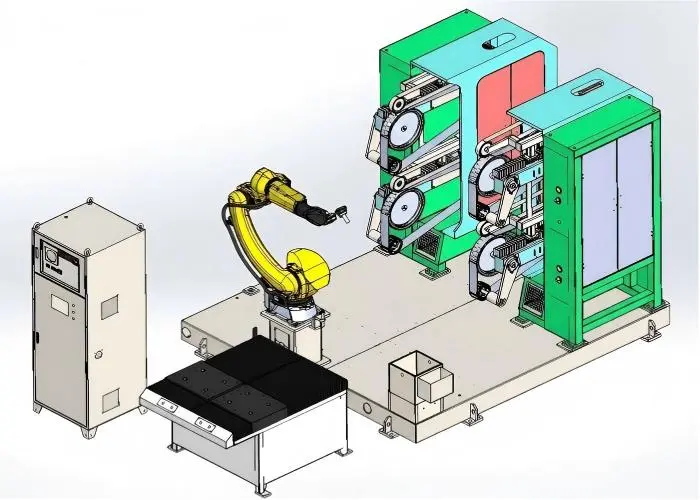
Low pressure die casting machine for brass faucets & valve bodies. Siemens PLC control, 380 pcs/shift & quick die change. Get a free quote for factory price!
Two Manipulators Low Pressure Die Casting Machine
Description
Machine Description
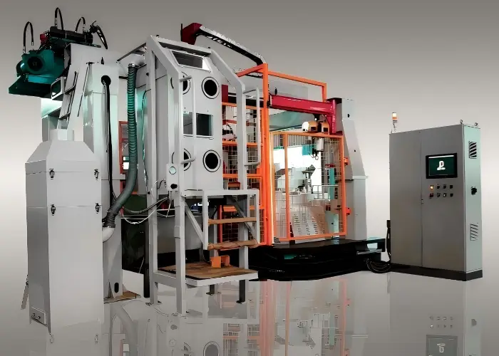
Our low-pressure die casting machines for brass are designed for manufacturing sanitary fittings, faucets, water meter bodies, and valve bodies. In this process, molten metal is filled directly into the die or sand mold from below, ensuring an absolutely controlled casting process with minimal turbulence. To meet various production capacities, we offer customizable configurations with one or two manipulators and one to three riser tubes, all powered by a freely programmable Siemens control system.
Machine Features
- Fully automatic machine on a single steel frame with one manipulator mounted on a linear transfer device and one furnace for the cost-effective production of high-quality casting products.
- Achieve high productivity with an output of approximately 380 castings per 8-hour shift.
- This machine with its automatic operation of the complete low pressure die casting process is highly suitable for the mass production of casting products with a noticeably short die changing time.
Packaging Standards
All machines are packaged in export-standard wooden cases with moisture-proof treatment. 👉 View packaging guide →
Technical Parameters
| No. | Equipment / Parameter Description | Value / Specification |
|---|---|---|
| 1 | BASIC EQUIPMENT | ONE MANIPULATOR |
| 1.1 | INDUCTION FURNACE | |
| CHANNEL INDUCTION FURNACE | 3 INDUCTORS | |
| CAPACITY | 1800 kg | |
| MELTING CAPACITY | 350 kg/h | |
| POWER COSUMPTION | 3*35 kW | |
| POWER CONSUMTION @ TEMPERATURE HOLDING 950°C | 35 kW | |
| 1.2 | MANIPULATOR | 1, LINEAR GUIDING |
| Max. Speed of Manipulator (S) | 20 m/min | |
| 1.3 | HYDRAULIC AGGREGATE | SERVO MOTOR 1* 7.5 kW |
| HYDRAULIC LIQUID | Ethylene glycol | |
| CYLINDRES | Dipping: 63*100*2 sets Rotary: 63*215*1 set Lifting: 63*250*1 set Die Closing: 50*372*1 set Ejector: 32*50*2 sets |
|
| NOMINAL WORKING PRESSURE | 80 bar | |
| HYDRAULIC LIQUID TEMPERATURE | ≤ 52 °C | |
| 1.4 | WATER DISTRIBUTION UNIT | |
| Cooling water for furnace coils, graphite bath and hydraulic system | ||
| pH value | 7 ~ 8.5 | |
| Water pressure | 3 – 5 bar | |
| Water temperature | 20 ±2 °C | |
| Water Flow | ≥15 l/min – ≤80l/min | |
| 1.5 | AIR PRESSURE UNIT | |
| Compressed air for die cleaning, pneumatic valves, furnace cleaning, casting, and security valves etc. | ||
| Compressed air pressure | 0.6 bar | |
| Compressed air consumption | 15 m³/h | |
| 1.6 | DRIVE UNIT | |
| SERVO MOTOR: | 1* 7.5 kW | |
| 1.7 | FURNACE COVER | |
| RISER TUBE FLANGE | 1 | |
| PROTECTION TUBES FOR THERMOCOUPLES | 2 | |
| RISER TUBE | 1 | |
| CERAMIC SEALING | 1 | |
| CHARGING TUBE AND COVER FOR MANUALLY OPENING | 1 | |
| 1.8 | GRAPHITE BATH | 1 |
| Temperature controlled coating bath, SS316L material | ||
| 1.9 | GAS BURNER | |
| Gas burner mounted on the furnace cover for riser tube heating and pre-heating. | ||
| 1.11 | CONTROL AND POWER CABINET | 1 |
| PLC CONTROL | Siemens S7/300 | |
| HMI (TOUCH SCREEN) | 1 | |
| OUTER DIMENTIONS (L * W * H) | 1200 * 500 * 1800mm | |
| 1.12 | REMOTE SYSTEM | |
| PC via Team Viewer and Internet connected | ||
| 2 | MAIN OPTIONS | |
| 2.1 | PIECE REMOVAL UNIT | |
| Automatically removal unit, equipped with an unloading device to transport the castings to storage trolley directly. | 1 | |
| 2.2 | SHOT BLASTING DEVICE | |
| Copper or brass chips blasting for die cleaning | 1 | |
| 2.3 | FILTER AND SUCTION UNIT FOR CASTING VALVE | |
| For zinc oxide dust suction to cleaning furnace dust after each casting | ||
| 2.4 | CRANE WITH ELECTRIC HOIST | 500 KG |
| 2.5 | PNEUMATIC OPENING OF THE CORE INSERTING WINDOW | |
| Automatically opening by a pneumatic cylinder; manually closing after core setting is finished. | ||
| 3 | ELECTRICAL OPTIONS | |
| 3.1 | EMERGENCY POWER CONTACTOR | 1 |
| With emergency stop buttons; for security purpose: there is automatic locked doors and complete fence unit. | ||
| 3.2 | SPECIAL CABLES | 10 M |
| 4 | DIE OPTIONS | |
| 4.1 | DIE FLANGES | |
| 4.2 | TEMPERATURE MEASURMENT OF THE DIES | PID control |
| 4.3 | TEMPERATURE MEASURMENT GRAPHITE BATH | PID control |
| 4.4 | PUMP CIRCUIT FOR CONTINUOUS CLEANING OF THE GRAPHITE BATH | |
| 4.5 | Max. die dimensions | 600 * 400 mm |
| 4.6 | Max. die thickness | 2 * 120mm |
| 4.7 | Max. die opening stroke | 372 mm |
| 4.8 | Max. die weight | 250 kg |
| 4.9 | Max. force of die closing | 2400kg |
| 4.10 | Max. force of ejector | 1000 kg |
| 4.11 | Max. die ejector stroke | 48 mm |
| 5 | HEATING GAS OPTIONS | |
| 5.1 | Propane pressure | 0.5 bar |
| 5.2 | Propane flow | 0.225 m³ / h |
| 6 | UTILITIES OPTIONS | |
| 6.1 | Equipment Size: L * W * H | 5200 * 5000 * 3600 mm |
| 6.2 | Total Weight | 13000 kg |
| 6.3 | Total Power | 125 kW |
| 6.4 | Operating Voltage | 380 V |
Application Fields
The ZL200Ⅱ 50kg spherical sand mixer is used across multiple industries to produce precise, high-quality foundry sand cores.
Brass Faucet Manufacturing
Precision cores for brass plumbing fittings and faucet components
Valve Production
Complex internal cavities for industrial and residential valves
Automotive Parts
Engine components and transmission parts requiring precise cores
Plumbing Hardware
Pipe fittings, connectors, and bathroom hardware components
Construction Hardware
Decorative and functional hardware for building applications
General Foundry
Custom sand cores for various metal casting applications