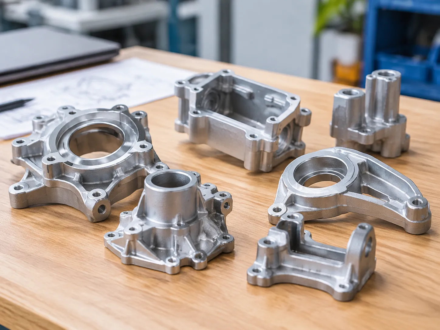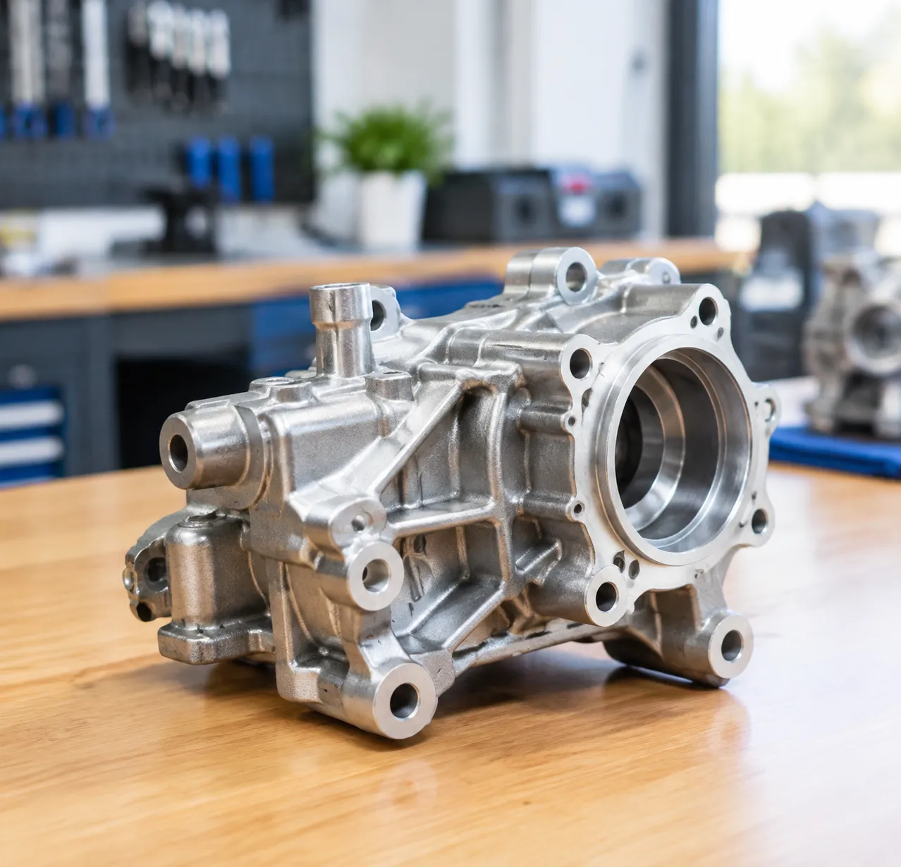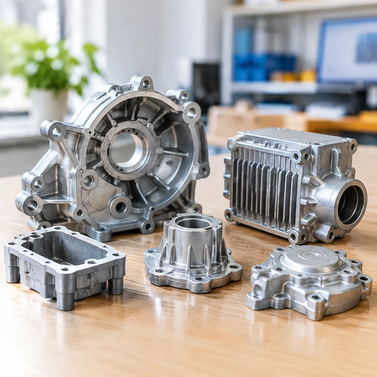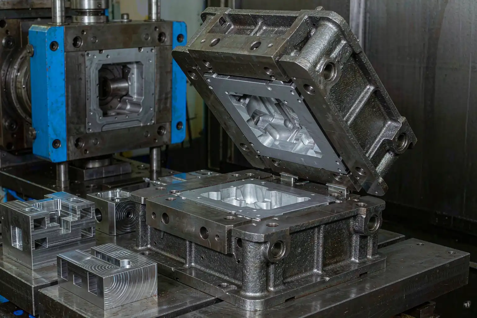
Zinc die casting runs at lower temperatures and injection pressures than aluminum or magnesium. The molten Zamak sits around 410 to 430 °C versus 660 °C for aluminum, and the injection pressure is roughly half. The result is gentler on the tool. A a properly designed mold for Zamak 3 or Zamak 5 will routinely run a million shots before any major rework. A a well-designed mold on a stable part can run five million shots. That long life is one of the reasons zinc is competitive with plastic injection molding for medium-volume hardware.
The friendliness is not free. The same low temperature and pressure that extend tool life also mean the casting defects that punish tooling — soldering, erosion, heat checking — appear more slowly. A a mold that is poorly cooled still works, it just makes bad parts. A a mold that is poorly gated makes the same bad parts every cycle. The design rules for zinc focus on getting the metal into the cavity smoothly and getting the heat out out consistently, not on surviving harsh conditions.
Tool Steel Selection

The two tool steels that cover the bulk of Zamak tooling are:
| Steel | Typical use | Hardness | Notes |
|---|---|---|---|
| P20 (pre-hard) | Cavities for short to medium runs | 30 to 36 HRC | Machinable, no heat treat after machining |
| H13 | Cavities for long runs, slides, cores | 48 to 52 HRC | Harder, wears longer, harder to machine |
| S7 | Slides, ejector pins | 54 to 58 HRC | Tough, holds impact |
For Zamak 3 and Zamak 5 parts with run rates under 500,000 shots, P20 is the default. The pre-hard condition is machinable, the cavities can be cut on a standard CNC, and the mold is ready to run without a heat-treat cycle that might distort the cavity. For longer runs or parts with thin walls where steel wear matters, H13 cavities are worth the extra machining cost. For slides and wear parts, S7 holds an edge and survives impact better than H13.
A few zinc-specific caveats matter for steel choice:
- Avoid copper-bearing tool steels (such as P20 with copper additions). The molten zinc dissolves copper, leaving a rough cavity surface and contaminating the casting.
- Keep the cavity surface finish to SPI-A2 or better. Zamak replicates the cavity finish directly, and a coarser finish means more polish work on every part.
- Through-hard the corners and thin features. Soft corners round off under injection pressure and start producing flash after a few thousand shots.
Gate, Runner, Overflow Design
Zinc flows easily and freezes quickly. The gate design for Zamak is generally larger than for aluminum, because the lower temperature means the metal loses heat fast and a small gate freezes off before the cavity fills. A a typical gate thickness for a medium Zamak part is 1.5 to 2.5 mm, versus 0.8 to 1.5 mm for an equivalent aluminum part.
The runner system should be:
- Cold chamber style, with the runner sized to feed the cavity in under 0.1 second.
- Balanced for multi-cavity molds, so every cavity fills at the same time. Unbalanced runners produce short shots on the starved cavity.
- Vented at the end of fill, with overflow wells sized to catch the air that the zinc displaces. Without overflow, the air compresses and produces porosity or misruns at the far end of the part.
The gate location matters more for finish than for fill. A gate on a visible surface leaves a witness mark that has to be polished off. A gate on a non-visible surface (the back of a handle, the inside of a housing) lets the plater skip the gate-polish step. For parts heading to bright chrome, the gate location is a plating decision as much as a casting decision.
Cooling Layout
Cooling is the single biggest determinant of cycle time and casting quality on a zinc tool. The rule of thumb is that the cycle time on a Zamak part equals roughly the time to cool the thickest section to ejection temperature. A a 3 mm wall casts in about 12 to 18 seconds with good cooling. A a 6 mm wall casts in 30 to 50 seconds. A a poorly cooled 6 mm wall can take two minutes or more, which is the difference between a profitable mold and a museum piece.
Cooling layout rules:
- Cooling channels as close to the cavity surface as practical. A channel 10 mm below the surface is far more effective than one at 20 mm. The trade-off is that channels too close can mark the casting surface or crack under pressure.
- Baffles or bubblers for deep cores. A a deep core cannot be cooled by a straight channel. A baffle (a plate that deflects water around the core) or a bubbler (an inlet tube aimed at the core) is needed.
- Conformal cooling for high-volume tools. Conformal channels that follow the cavity contour are 30 to 50% more efficient than straight drilled channels. The cost is the additive-manufactured insert, which only pays off on long-run tools.
- Separate cooling zones for slides and cavities. Slides cool differently from the main cavity. If they share a circuit, the slide runs hot or the cavity runs cold, neither good.
Ejection and Slide Systems
Zamak shrinks about 0.1 to 0.15% on solidification, which is roughly half of aluminum’s shrinkage. The lower shrinkage means parts stay in the cavity longer at ejection temperature, which is good for dimensional stability but means the ejection system has to move the part cleanly off the cavity wall.
Ejection system rules:
- Ejector pins at thick sections. The part sticks to the cavity wall where the mass is greatest. Put pins where the wall is thick and the part is stiff.
- Stripper plates for thin-walled parts. Thin parts deform under ejector pins. A a stripper plate pushes the part off the cavity evenly and avoids distortion.
- Slides for side actions. Side actions for side-action features. A a slide that is poorly cooled will gall after a few thousand shots. A a slide that is poorly lubricated will score the cavity.
- Ejector pin return springs, not just springs. Return springs alone wear out. A a positive return (mechanical linkage) is more robust.
Mold Life and Maintenance
A well-designed Zamak mold will last a million to three million shot before requiring cavity rework. The first thing to wear is usually the gate area, which sees the highest thermal cycling. The second is the cavity corners. The third is the ejector pins, which take impact every cycle.
A preventive maintenance schedule extends life dramatically. The schedule looks like:
| Interval | Action | |
| Daily | Spray lubricant, check ejection | |
| Weekly | Polish gate area, inspect for soldering | |
| Monthly | Check cooling channels for scale | |
| Quarterly | Pull slides, polish wear surfaces | |
| 500,000 shots | Re-cut gate area | |
| 1,000,000 shots | Full cavity re-polish |
A plater who skips the weekly gate polish usually sees soldering start at the gate and spread to the cavity within a few hundred thousand shots. The fix is a five-minute polish, not a cavity re-cut.
Common Defects from Poor Mold Design
Most Zamak casting defects trace back to mold design, not alloy or machine. The most common and their design fix:
- Cold shuts — the metal freezes before the cavity fills. Fix: thicker gate, hotter die, faster injection.
- Flash — the cavity opens under pressure. Fix: more clamping force, larger platen, harder cavity steel, tighter slide fit.
- Soldering — zinc sticks to the cavity wall. Fix: better cavity steel, polished cavity surface, proper die release spray, balanced cooling.
- Porosity — air trapped in the cavity. Fix: better venting, more overflow, faster injection, balanced runners.
- Warping on ejection — uneven cooling. Fix: balanced cooling, longer cooling time, ejection at uniform temperature.
Each defect has a quick root-cause path. A a five-minute check on the cycle log, the cooling water temperature, and the gate area usually narrows it to one of the design rules above.
Making the Call
Zinc die casting rewards plants that invest in tool design at the front end. The mold is the single biggest determinant of part quality, cycle time, and reject rate, and the same mold runs for years. Cutting corners on tool steel, cooling layout, or gate design shows up as plating rejects six months later, when the mold is in production and the cost of fixing it is high.
The first step is the same as for any tooling investment: pull the part print, sketch the cavity layout, and ask a tool designer to review the gate location, cooling layout, and ejection system before cutting steel. A a 30-minute review at this stage saves a 30-day rework cycle later.
For plants already running Zamak tooling, the audit is straightforward: pull the last quarter of casting rejects, count the ones that trace to mold design, and price them. If the price exceeds the cost of a re-cut or a cooling retrofit, the retrofit has a business case before any vendor walks in.
A Hardware Maker’s Mold Retrofit
A door hardware maker in the Xiamen region had been running the same Zamak 5 lever mold for nine years. Production volume was roughly 800,000 parts per year. The original tool steel was P20 with a basic straight-drilled cooling layout. By year seven the cavity corners were rounding off, the gate area was soldering regularly, and the cycle time had stretched from 18 seconds to 27 seconds as scale built up in the cooling channels.
The maker faced three choices: scrap the mold and cut a new one ($80,000), retrofit the cavities with H13 inserts ($28,000), or rebuild the cooling channels and accept the corner wear ($15,000). The maker chose the H13 insert retrofit. The new inserts brought the corner wear back to spec, the gate area soldering dropped to near zero, and the cycle time dropped to 19 seconds — faster than the original mold because the new inserts had better surface finish. Total retrofit cost was $28,000 and the recovered production was worth roughly $190,000 per year from cycle time and reject reduction. Payback was under three months.
The lesson is that mold retrofits often beat new tools, especially for parts that have stabilized in geometry. A a 30-minute mold audit by an experienced tool designer will identify the wear points and the cooling gaps in any tool that has run more than 500,000 shots. The retrofit cost is a fraction of the new tool cost, and the cycle-time recovery usually pays for it in the first quarter.
The same logic applies to the cooling layout. A a conformal cooling insert is expensive as an aftermarket retrofit, but a well-designed baffle or bubbler upgrade costs a few thousand dollars and can cut 20% off the cycle time on a deep-core part. The audit is cheap. The retrofit is cheap. The recovery is not.