Robotic Finishing Cell Safety: Light Curtains, Dust and Lockout
A robotic grinding and polishing cell concentrates several hazards that most machining operations keep separate: high-speed rotating tools, flying sparks, fine combustible metal dust, loud broadband noise, and a robot arm moving with enough force to cause serious injury. Treat the cell as a system, not a collection of guards, and the safety design becomes a process-engineering problem rather than a compliance checkbox. In this article we walk through the hazard inventory for deburring and polishing, the safeguarding layers we specify on a DZ Machinery cell, the specific problem of aluminum and zinc dust explosions, and the lockout and teach procedures that keep the system safe in daily use.
Hazard inventory in grinding and polishing
Before specifying a guard, list what can actually hurt someone. For die-cast aluminum and zinc finishing the dominant hazards are:
- Rotating tools. Abrasive belts run at 15 to 35 m/s surface speed; flap wheels and buffing mops spin at several thousand rpm. Contact with skin removes flesh faster than most people expect, and a snagged glove can pull a hand into the wheel.
- Ejected particles and sparks. Gate removal on a casting throws hard fragments. At a 25 m/s belt, a 2 mm particle leaves the contact zone at a speed that penetrates ordinary safety glasses unless they are rated.
- Combustible metal dust. Aluminum fines below roughly 500 microns, and especially the fraction below 100 microns, form explosible clouds at the right concentration. Zinc dust is less energetic but still classified as combustible. This is the hazard most plants underestimate.
- Noise. Belt grinding of aluminum runs 85 to 98 dB(A) at the operator position. Eight-hour exposure above 85 dB(A) requires hearing protection and often engineering noise control.
- Heat. Friction at the contact point raises local part temperature; a freshly finished part or wheel can burn on touch.
- Robotic motion. The 6-axis arm moves through a large envelope with forces that can crush or strike. The risk is highest during teach and recovery from a fault.
Each of these maps to a layer of control. The principle we design to is that no single layer is trusted alone: a guard fails, the interlock still stops the robot; an interlock is bypassed, the light curtain still trips; the curtain is defeated, the speed and separation monitoring still limits the arm.
The control layering for each hazard is summarized below so the design intent is explicit rather than implicit.
| Hazard | Primary control layer | Backup layer | Last-resort layer |
|---|---|---|---|
| Rotating tools | Fixed enclosure and interlocked doors | Light curtain at opening | Teach-mode enabling switch |
| Ejected particles and sparks | Rated enclosure and polycarbonate panel | Captured extraction airflow | Rated eye and face protection |
| Combustible metal dust | Wet or rated dry capture at source | Explosion relief and isolation | Grounding and wet cleaning |
| Noise | Enclosure attenuation | Local acoustic screening | Hearing protection program |
| Robotic motion | Speed and separation monitoring | Light curtain trip | Lockout for in-envelope work |
Safeguarding the cell: guarding, interlocks, and light curtains
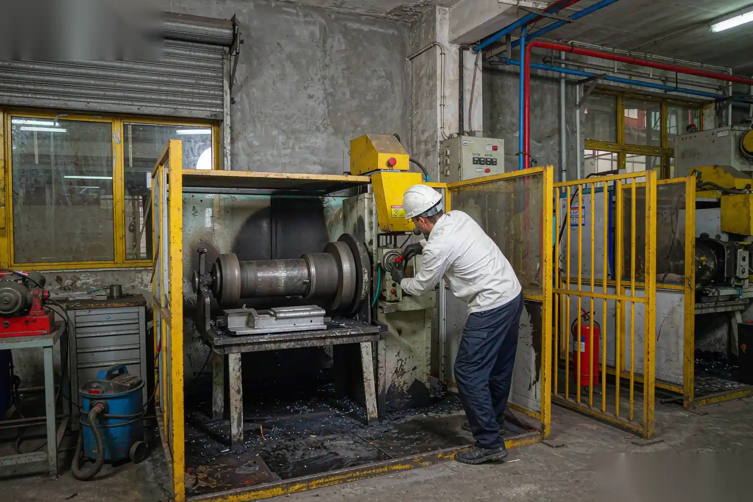
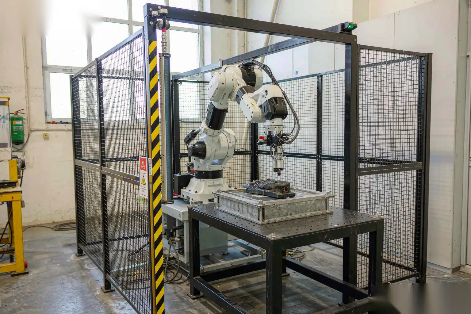
The physical boundary is the first layer. We enclose the cell on all sides that face people with fixed guarding rated to contain ejected particles, with a viewing panel of rated polycarbonate rather than glass. Access for loading and maintenance is through interlocked doors, not through removable panels someone can leave off.
Interlocks are wired as positively driven safety contacts, not as proximity sensors that can be masked. A door opened during operation drops the robot to a safe-stop state within the monitored stop time, and the spindles lose power through a monitored safety relay. The interlock state is logged, so a bypassed door shows in the cell controller and on the line dashboard.
Light curtains form the active safeguarding at the load and unload opening. Specification points that matter:
- Resolution. For a hand and arm detection we use a 14 mm or 30 mm resolution curtain depending on the required detection zone. Finer resolution costs cycle time at the opening, so it is matched to the access risk.
- Height and coverage. The curtain must cover the full opening including the space above the belt line where a reach-over is possible. We extend the guarded height and add a fixed top Guard where reach-over risk exists.
- Response and stop time. The total time from beam break to robot standstill must be shorter than the time for a person to reach the hazard. We calculate the stopping performance of the robot plus spindle and set the curtain standoff distance accordingly using the standard reach formula. If the cell cannot meet the distance, we reduce robot speed in that zone.
- Muting and blanking. Load stations need the curtain to mute during a confirmed pallet transfer. We use fixed blanking only on defined beams and require a presence confirmation from the fixture, never an operator-held mute, so a person cannot walk through a muted curtain.
Speed and separation monitoring is the layer that lets the robot keep working while a person is in the envelope during setup. The controller tracks the person’s position from safety-rated sensors and slows or stops the arm if the separation distance closes. This is what makes teach and recovery practical without a full cage entry for every fault.
Combustible metal dust: aluminum, zinc, and explosion control
Dust is the hazard that turns a routine finishing cell into a regulatory and insurance problem. Aluminum fines generated by dry grinding are fine, hot, and readily ignitable. The control strategy follows the standard hierarchy: prevent ignition, control concentration, and provide relief if a deflagration occurs.
Key design elements on a DZ cell:
- Wet capture at source. We prefer wet-type dust collection or a flooded capture at the contact point for aluminum, because water both captures the fine and removes the ignition source that a dry spark-arrestor baffle can still allow. Where wet collection is not acceptable for the process, we use a dedicated aluminum-rated dry collector with continuous protection.
- Dedicated collectors, never shared. Aluminum dust must not mix with other materials or with steel dust in a common collector, because the reaction and the cleaning procedure differ. Each cell or cell group gets its own rated unit.
- Explosion relief and isolation. The collector and ductwork are specified with relief vents sized to the deflagration parameters of the specific dust, and with isolation devices on the duct so a flame front cannot propagate back into the cell or across to another unit.
- Grounding and bonding. The entire airflow path, cell frame, and tool are bonded to a common ground to prevent static discharge ignition. Plastic components in the airstream are avoided or made static-dissipative.
- Housekeeping and cleaning. Accumulated dust on ledges and floors is the real reservoir. We design surfaces to shed dust toward the capture flow and specify a wet cleaning procedure; compressed-air blowing of aluminum dust is prohibited because it re-suspends the cloud.
The grinding and polishing dust safety guide goes deeper into threshold diameters, minimum ignition energy, and the cleaning protocols we hand to the plant’s EHS lead. The point for the cell designer is that dust control is part of the machine, not a separate janitorial task. A cell that generates fines faster than it captures them is unsafe by design.
Zinc behaves differently from aluminum: its dust is combustible but its minimum ignition energy is higher and the oxide layer is less reactive. The same capture discipline applies, but the relief sizing and wet-versus-dry decision are made per alloy and per local code. We do not assume one dust strategy fits both.
Lockout and tagout for energy isolation
A light curtain stops a person from entering a live cell, but it does not make the cell safe to work inside. For tool changes, fixture maintenance, and any reach into the envelope, lockout and tagout isolates all hazardous energy: electrical, pneumatic, and the stored kinetic energy in the robot and spindle.
Our procedure on a DZ cell:
- A single clearly marked isolation point cuts control power to the robot controller, spindle drives, and the automatic abrasive changer. Locking this point removes the ability to energize the cell.
- Pneumatic isolation for the floating spindles and fixture clamps is separately locked, because a clamp can still close on a hand from stored air after electrical lockout.
- The robot is parked in a defined safe pose and the teach pendant is set to a mode that requires the key, so a fault recovery cannot restart motion.
- Stored energy is dissipated: the spindle is confirmed stopped, the floating mechanism depressurized, and any counterbalance verified safe before a person enters.
- The lock is the technician’s, not a shared plant lock. Tagout records who, why, and when, and the cell status reflects the lock on the dashboard.
A common failure is treating the light curtain as a substitute for lockout. It is not. The curtain protects a passer-by; it does not protect someone working inside the envelope against a restart from a remote fault clear or a maintenance override. The rule we train: if you are inside the guarded space, the cell is locked out, full stop.
Teach mode and fault recovery procedures
Most serious incidents in robotic finishing happen during teaching and recovery, when an engineer is inside the envelope with the system partially live. The cell design must make safe teaching the easy default.
- Teach pendant with three-position enabling switch. The robot moves only while the switch is held in the mid-position; release or over-press stops it. This is non-negotiable and is enforced in firmware, not as a procedure.
- Reduced speed in teach. Motion in teach mode is capped at a low speed, typically 250 mm/s or less, so a collision is survivable.
- Single-channel control. In teach, only the pendant can command motion; external starts are disabled. A fault clear does not auto-resume the program.
- Defined recovery. After an estop or fault, the cell requires a deliberate restart sequence from the pendant, re-homes the robot, and confirms the fixture state before resuming. It does not pick up mid-path blind.
- Visual and audible indication. Teach mode is announced by a distinct beacon and tone so anyone approaching knows the cell is in a partially live state.
We document these steps in the cell manual and train the customer’s maintenance staff on them before handover, because a safe cell operated by an untrained person is not a safe cell. The training covers not just the buttons but the why: why a muted curtain is dangerous, why lockout is separate from the guard, and why zinc and aluminum dust are handled differently.
Integrating safety into a DZ cell design
Safety is designed in from the first layout, not added after the process is fixed. On a DZ Machinery deburring and polishing cell the safety architecture is built as follows.
- Risk assessment first. We run a task-based risk assessment against the actual part, tool, and cycle before fixing the layout, identifying each hazard, its likelihood, and the required risk-reduction layer. The safeguarding spec flows from that assessment, not from a generic template.
- Safety-rated control. The cell controller uses a safety-rated PLC and drives with monitored stop, safe speed, and safe torque-off functions, so the safeguarding is enforced in certified hardware rather than in application logic that can be edited away.
- Zoned design. The cell is divided into load zone, process zone, and maintenance zone, each with its own safeguarding and its own entry procedure, so a person loading parts is never exposed to the process envelope.
- Dust and noise engineered together. The enclosure that contains particles also attenuates noise, and the extraction that controls dust also pulls heat and sparks away from the contact point. The three hazards share one engineered airflow.
- Audit trail. Interlock status, estop events, light-curtain trips, and lockout state are logged with timestamps, giving the plant an EHS record and a way to spot bypass attempts before they cause harm.
For plants building the wider automation, the surface finishing automation complete guide for foundries places this cell safety architecture inside the full line from casting through inspection, and the die casting secondary operations guide covers how trimming, machining, and finishing sequence together so the safety boundaries align rather than overlap.
Commissioning and ongoing verification
A cell leaves our floor safe, but it stays safe only with verification. We commission with the following checks and recommend they repeat at defined intervals.
- Stop-time measurement. We measure the actual robot and spindle stop time and confirm the light-curtain standoff distance still protects, because wear and firmware changes drift the numbers.
- Interlock functional test. Every door and guard interlock is tripped under load to prove the safe-stop triggers and the spindle loses power.
- Dust concentration check. Where a continuous monitor is fitted, we verify the alarm threshold against the measured generation rate at full cycle.
- Lockout drill. We run a supervised lockout with the customer’s staff to confirm the isolation points and the procedure are understood, not just documented.
The recurring theme is that safety is a measured quantity, not a feature list. A cell that passes at commissioning and is never re-verified slowly accumulates bypasses, worn curtains, and defeated interlocks until the next incident teaches the lesson. We build the logging and the test points so that verification is a routine part of preventive maintenance rather than a yearly scramble.
DZ Machinery designs robotic deburring, grinding, and polishing cells with integrated safeguarding, explosion-rated dust collection, and documented lockout and teach procedures built in from the first layout. Talk to our engineering team about your finishing cell and we will scope the safety architecture against your alloy, your part, and your local code before any equipment is built.