Die Casting EV Battery Housings: Megacasting Scale, Leak Tightness and Finishing Requirements
Battery housings are the most demanding structural die casting application in volume production today. They are large, they must be leak tight for fifteen years, they must survive crash loads, they carry thermal management hardware, and they are joined by processes that impose their own tolerance requirements. Getting any one of those wrong is expensive, because a housing is a high-value part with a long supply chain leading into it. This article walks through the engineering decisions in the order they actually get made: machine size, alloy, porosity control, leak test specification, dimensional control, joining, thermal and fire behaviour, and then the finishing step that determines whether the sealing surfaces work.
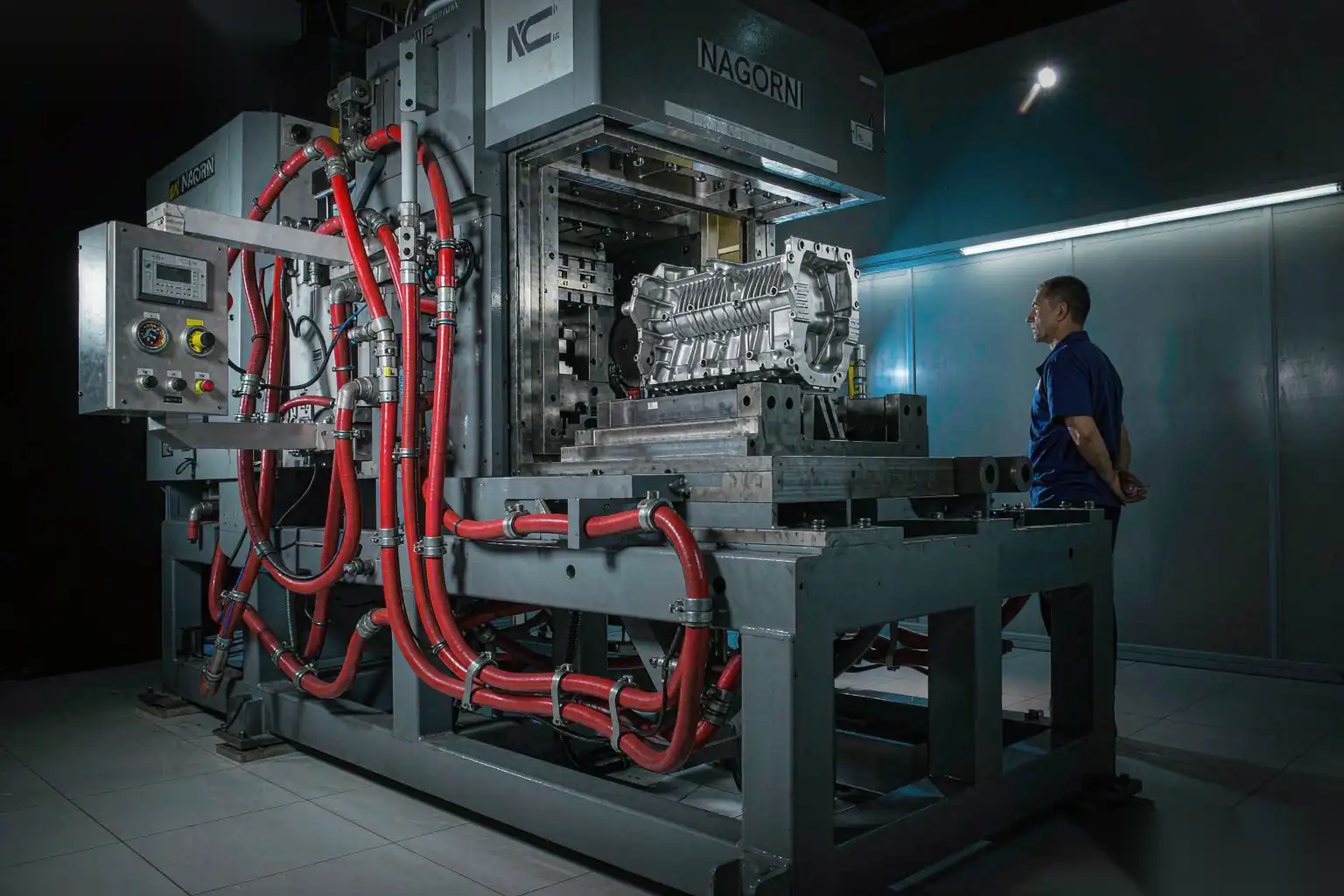
The Megacasting Trend: Clamping Force Versus Part Size
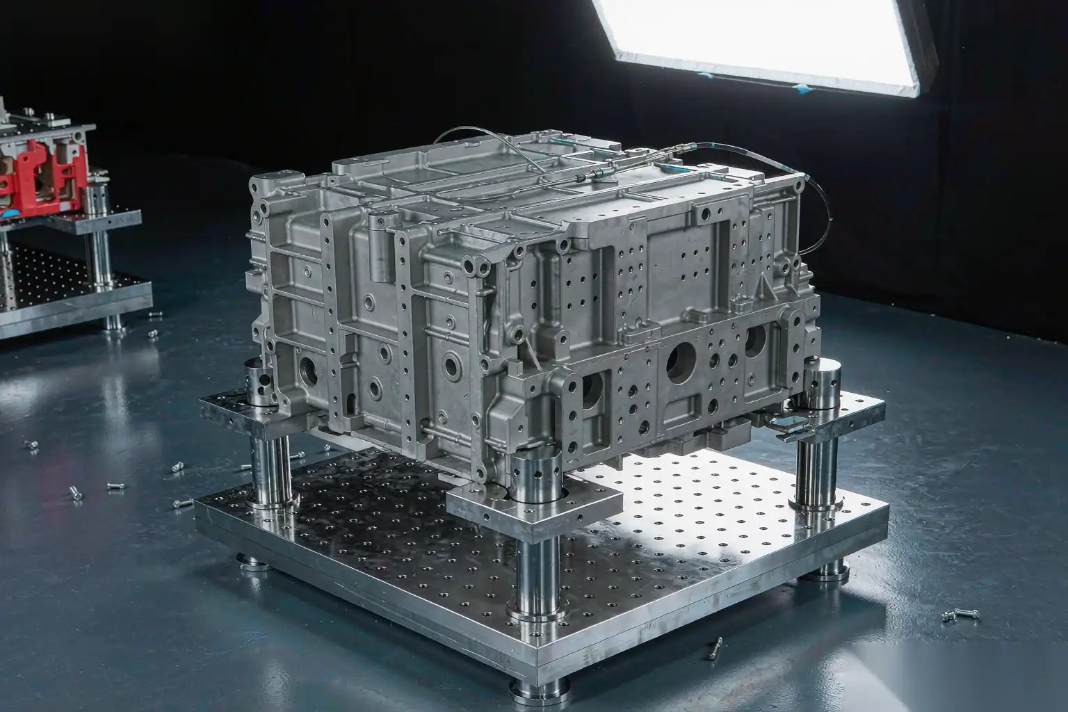
The term megacasting refers to casting a large structural component in a single shot rather than assembling it from dozens of stampings and smaller castings. For battery housings the driver is part consolidation: fewer joints means fewer leak paths, fewer fasteners, less sealing material and a shorter assembly line.
The governing equation is simple and it sets the machine size. Clamping force must exceed the separating force generated by injection pressure acting on the projected area of the casting, including runner, overflows and biscuit.
Force in tonnes equals projected area in square metres, times specific injection pressure in megapascals, divided by 9.81.
| Part class | Projected area | Specific injection pressure | Calculated clamp force | Machine class |
|---|---|---|---|---|
| Corner node, small bracket | 0.08 m2 | 80 MPa | 650 t | 800 t |
| Structural rail, 1.0 m | 0.30 m2 | 70 MPa | 2,140 t | 2,500 t |
| Rear underbody, 1.4 m | 0.60 m2 | 65 MPa | 3,970 t | 4,000-4,500 t |
| Battery tray, 1.4 x 1.0 m | 1.40 m2 | 60 MPa | 8,560 t | 9,000 t |
| Battery tray, 1.6 x 1.2 m | 1.92 m2 | 55 MPa | 10,760 t | 12,000 t |
Add 15-20 percent margin to the calculated value to keep the die from flashing as the machine and tie bars deflect under load. That is why 9,000 and 12,000 tonne machines exist for this work.
The practical consequences that follow from scale:
- Shot weight climbs fast. A 1.4 x 1.0 m tray at 3 mm nominal wall with ribs and bosses is typically 45-70 kg of aluminium, plus a runner, overflows and biscuit that can add another 25-40 kg. Total shot weight of 80-110 kg is normal on the large end.
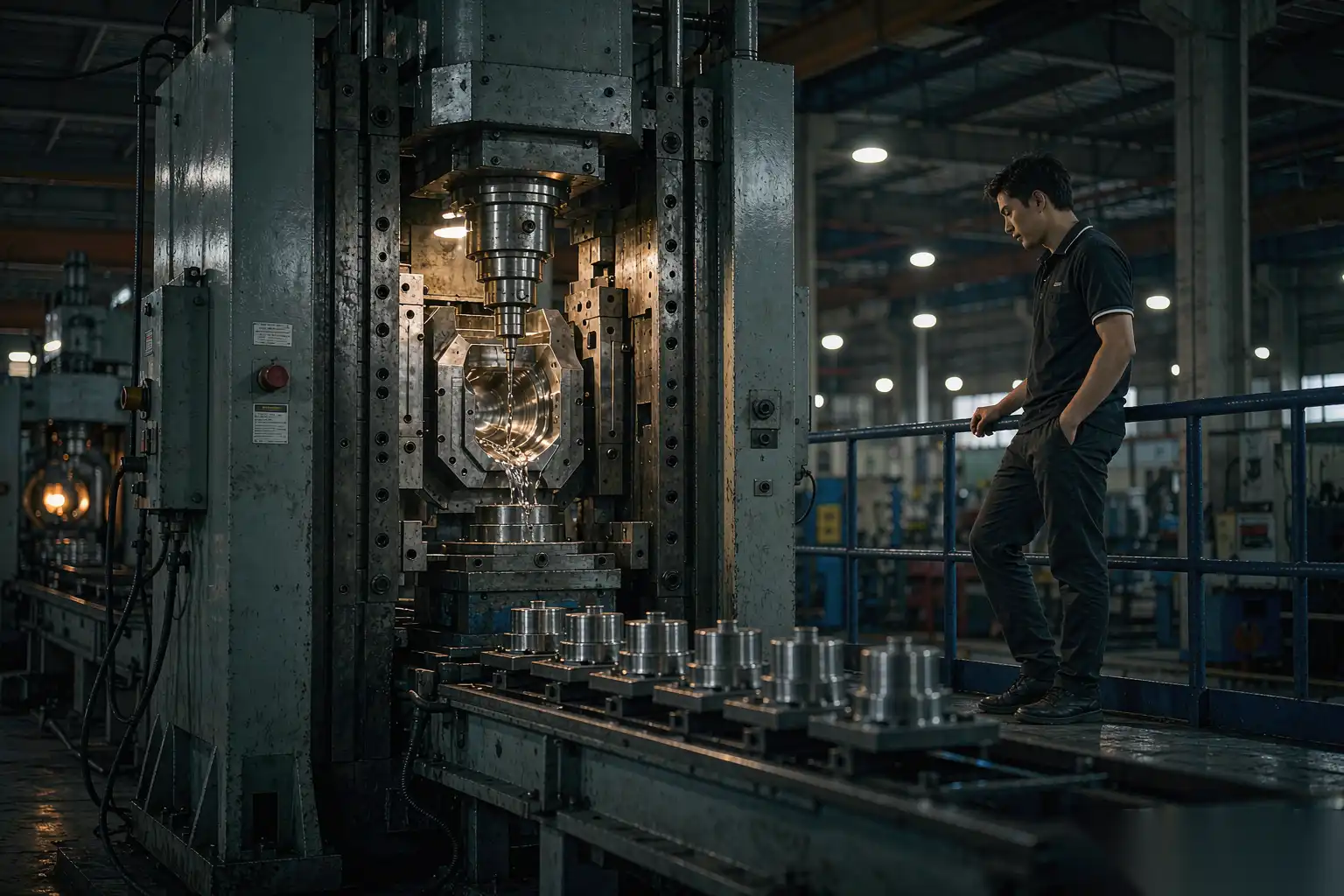
- Fill distance is long. Metal must travel 1.5 m or more through thin section, which forces very short fill times, typically 60-120 ms, and high gate velocities. This is the main reason megacastings need vacuum: the entrained gas from a 100 kg shot through a long thin cavity is unacceptable.
- The biscuit and runner are large. Removing a 10-15 kg biscuit and a full perimeter runner is a real material handling and cutting problem, not a trimming afterthought.
- Thermal management of the die is harder. A 20-40 tonne tool with several hundred metres of cooling line needs zoned control and careful water treatment; hot spots on a large die are what drive heat checking and dimensional drift.
- Dimensional stability across a 1.6 m part over a production run is the hardest single requirement. More on this below.
Alloy Requirements: Ductility, Crash Energy and Corrosion
Battery housings are structural and safety relevant, so the alloy has to deliver elongation and energy absorption, not just strength. The standard as-cast or T7 targets we work to:
| Property | Typical requirement | Why it matters |
|---|---|---|
| Yield strength | 120-150 MPa | Determines intrusion resistance in side impact |
| Ultimate tensile strength | 240-300 MPa | Global strength |
| Elongation at break | 8-15 percent | The real crash requirement; brittle housings crack |
| Bend angle, 3-point bend | 45-70 degrees at specified support span | The acceptance test most OEMs actually use |
| Charpy or impact energy | Application specific | Low temperature behaviour |
| Thermal conductivity | 120-160 W/mK | For integrated cooling plates |
| Corrosion, salt spray | 1,000 h with controlled mass loss | Underbody exposure |
The alloys used are almost all low-iron, strontium-modified, manganese-bearing Al-Si-Mg or Al-Mg-Si systems, cast under high vacuum and used in the as-cast or T7 condition. T6 is generally avoided for housings because the strength gain is less valuable than the elongation retained by overageing, and because a full solution treatment on a 1.6 m part creates distortion and a blister risk that is not worth carrying.
Chemistry controls that matter more than most people realise:
- Iron below 0.15-0.25 percent. Iron forms plate-like intermetallics that nucleate porosity and cut elongation. Low iron is also why these alloys need manganese, to prevent die soldering, typically Mn at 0.4-0.8 percent with an Mn to Fe ratio above 2.
- Strontium modification at 100-250 ppm to convert acicular eutectic silicon to a fibrous morphology. This is the single biggest lever on elongation. Strontium fades with holding time, so it must be checked at the furnace, not assumed from the ingot certificate.
- Copper below 0.05 percent. Copper improves strength and age response but wrecks corrosion resistance and makes the alloy more susceptible to hot tearing.
- Magnesium 0.2-0.6 percent for the precipitation response; higher magnesium in the AlMg5Si2Mn family gives better as-cast ductility and anodising appearance.
- Hydrogen degassing to below 0.15 mL/100 g before casting, verified by reduced pressure test or an equivalent hydrogen probe at the holding furnace on a defined frequency.
- Grain refinement with Al-Ti-B at a controlled addition rate; too much grain refiner causes TiB2 agglomerates that act as porosity nucleation sites.
Crash performance is verified by component bend testing, not just by coupon tensile data. The standard approach is a three-point bend on the cast section at a defined support span and ram speed, at both room temperature and minus 40 °C, with an acceptance bend angle. Coupon elongation correlates with bend angle only within a given alloy family, so specify both.
Porosity Limits Near Machined Sealing Surfaces
Sealing surfaces are the critical zones. A pore that is harmless in a rib becomes a leak path when it intersects a machined gasket face or a threaded fastener hole.
- Set a maximum allowable pore diameter within a defined depth of any sealing surface. A common specification is 0.5 mm maximum pore diameter within the first 1.5 mm below the machined surface, and 1.0 mm maximum beyond that depth.
- Set a cluster limit, not just a single pore limit. A field of 0.4 mm pores is a leak path even though each pore passes. We typically specify that the total pore area fraction in any 25 x 25 mm window of a sealing surface must not exceed 1 percent.
- Specify gas content by volume. Structural vacuum castings should be under 2 mL/100 g, with best practice under 1 mL/100 g. Measure by reduced pressure test on a defined sampling plan and record it with the shot data.
- Machine allowance matters. If you leave 1.0 mm of stock on a sealing face, the surface after machining was 1.0 mm inside the casting, where the pore population is very different from the skin. Specify the machining allowance on the drawing and qualify the porosity limit at the machined depth, not at the as-cast surface.
- Inspection method: X-ray to ASTM E505 or E155 reference radiographs for grade acceptance, plus computed tomography on first article and on a defined audit frequency for critical zones. Dye penetrant is not reliable on as-cast surfaces and should be restricted to machined faces.
- Helium leak test is the functional verification and it supersedes visual or radiographic judgement. A part that passes radiography can still leak through a connected pore network.
Because porosity control at this level depends on fill behaviour, the same porosity causes and solutions logic applies, but with much tighter limits and with vacuum as a hard requirement rather than an option.
Helium Leak Testing: Methods and How to Specify a Leak Rate
Helium testing is the standard for battery housings because it detects leak paths an order of magnitude smaller than air decay testing, and because helium is inert, non-flammable and present in air at only about 5 ppm, so background is low.
Two methods are in use, and they answer different questions.
| Method | How it works | Sensitivity | Best for |
|---|---|---|---|
| Vacuum chamber, integral test | Part sealed with test ports, placed in a chamber, chamber evacuated, part pressurised with helium, detector measures helium escaping into the chamber | Down to 1 x 10⁻⁷ mbar L/s | Total leak rate of the whole assembly, production line testing |
| Sniffing, localisation | Part pressurised with a helium mixture, operator or robot moves a sniffer probe over joints and surfaces | Down to 1 x 10⁻⁶ mbar L/s, location dependent | Finding where the leak is |
| Pressure decay with helium, accumulated | Part pressurised inside a sealed enclosure, helium that escapes accumulates and is measured after a dwell | Down to 1 x 10⁻⁵ mbar L/s | Larger parts where full vacuum chambers are impractical |
Specifying a leak rate properly requires five numbers, not one:
- Maximum allowable leak rate, expressed with units. A typical battery housing specification is 1 x 10⁻⁵ to 5 x 10⁻⁵ mbar L/s at the test pressure, equivalent to 1 x 10⁻⁶ to 5 x 10⁻⁶ Pa m3/s. Note the unit conversion: 1 mbar L/s equals 0.1 Pa m3/s. The most common specification error in this industry is a leak rate quoted in sccm or mbar L/s with no stated test pressure, which makes the number meaningless.
- Test pressure and direction. Battery trays are usually tested at 1.0-2.5 bar gauge, pressurising in the direction that would drive water inward in service, or under vacuum where that represents the real condition. State which.
- Test gas concentration. Sniffing is typically done with 5-10 percent helium in nitrogen or air for cost and safety; integral testing uses 100 percent helium or a defined mixture. The measured rate scales with concentration, so state it.
- Dwell and stabilisation time. Typically 5-30 s of fill, 10-60 s of stabilisation, then measurement. Too short a stabilisation gives false rejects on large volumes.
- Temperature. Helium leak rate changes with temperature and large housings come off the line warm. Specify testing at a stated part temperature band, typically 20-35 °C, or apply a documented correction.
Also specify the calibration regime. The reference leak standard must be certified, checked at the start of each shift, and the system must demonstrate a measurable response to it. Without a certified reference leak in the loop, every pass result is an assumption.
Gross leak detection should be run before the helium test. A quick air decay or pressure hold at 2 bar for 10-20 s catches the large defects cheaply and protects the helium detector from contamination, which otherwise causes long recovery times and phantom readings.
Where the housing is tested as part of a pack, remember that individual component limits do not add linearly in a useful way. A tray at 5 x 10⁻⁵ and a cover at 5 x 10⁻⁵ do not give a pack at 1 x 10⁻⁴ that anyone should accept; agree a system-level limit and allocate it down to components with margin.
Dimensional Tolerance and Flatness Across Large Parts
Large thin-wall castings move. The dimensional plan has to acknowledge that rather than pretend otherwise.
- Linear tolerance. For castings in this size range, ISO 8062-3 DCTG 6 to 8 is realistic, which at 1,000-1,600 mm nominal is roughly plus or minus 1.0 to 2.5 mm on general features. Tighter is possible on features formed by the same die half with a short datum chain, typically plus or minus 0.3-0.5 mm, and anything tighter should be achieved by machining, not by casting.
- Flatness. Sealing flanges are the critical case. A workable specification is 0.5 mm per 500 mm on the flange face, with an overall limit of 1.0-1.5 mm across a 1.4 m tray in the free state, plus a separate limit under a defined clamping condition that represents assembly.
- Datum strategy. Establish the datums in the die, not afterwards. All sealing features, fastener holes and cooling interface features should be dimensioned from a single datum system that is achievable in the die and then in the machining fixture.
- Measuring in the free state versus clamped. Say which. A flange that is 1.4 mm out in the free state may pull down to 0.2 mm with fasteners torqued, and if your gasket design can accommodate that, the free-state number should not be 0.5 mm. Over-specifying free-state flatness is one of the most common causes of unnecessary scrap on large housings.
- Wall thickness variation. Target plus or minus 10 percent on nominal wall. Thinner sections fill badly and thicker sections create hot spots and shrinkage.
- Thermal growth. Aluminium expands roughly 23 micrometres per metre per kelvin. A 1.6 m part measured at 20 °C and at 45 °C differs by about 0.9 mm. Inspection must be at a controlled temperature, typically 20 plus or minus 2 °C, and this has to be enforced in a plant that is not air conditioned.
- Verification cadence. Full CMM or laser scan on first article, then a defined feature set per shift, with a full scan at an agreed interval or after any tooling intervention. Track Cpk on the sealing features specifically; a drift there is the earliest warning of die wear or thermal imbalance.
Joining: SPR, Flow Drill Screws and Their Tolerance Effects
The housing has to be joined to itself, to the vehicle body and to internal structures. The two dominant mechanical joining methods for aluminium in this application are self-piercing rivets and flow drill screws, and both have hard geometric requirements that feed back into the casting design.
- Self-piercing rivets. SPR joins two or more sheets without a pre-punched hole by driving a semi-tubular rivet through the top layer and flaring it into the bottom layer. Requirements: total stack thickness typically 2.0-6.0 mm, the more ductile material on the bottom or die side, edge distance of at least 8-10 mm from the rivet centre to any free edge, and rivet pitch of at least 15-20 mm. On cast aluminium, elongation of at least 8 percent is needed to avoid cracking during flare. Access is needed on both sides, so the flange geometry has to allow a C-frame to reach.
- Flow drill screws. FDS uses a rotating fastener that generates heat by friction, extrudes a boss in the lower sheet and then threads into it. Requirements: lower sheet thickness typically 1.5-3.0 mm for a 5 mm screw, single-sided access, and a boss that protrudes 1.5-3 mm on the far side. FDS is preferred where access is one-sided or where the stack includes a cast section, and it produces a removable joint, which helps serviceability.
- Tolerance interaction. Both processes need the joint gap controlled. A gap above roughly 0.2-0.3 mm before joining causes poor rivet flare or strip-out, so the casting flange must be flat enough to be clamped closed, and the assembly fixture must clamp adjacent to every fastener. This is why flatness and the joining process specification are written together, not separately.
- Hole and feature position. FDS and SPR do not tolerate cumulative position error well. Position tolerance of plus or minus 0.5 mm on fastener locations is realistic for cast features and should be verified by functional gauging rather than by CMM only.
- Mixed material joints. Where the housing joins steel body structure, galvanic corrosion has to be managed with isolators, coatings or sealants. Specify it; it is not optional and it is not covered by the alloy’s own corrosion resistance.
- Sealing. Adhesive or liquid gasket in the joint is normal, and a formed-in-place gasket bead needs a groove with controlled width and depth, plus a surface clean and free of release agent residue. Residual die lubricant is a common cause of bead adhesion failure and is entirely a process discipline issue.
Thermal Management and Fire Resistance
The housing is part of the thermal system and part of the safety system.
- Cooling interface. Where a cold plate or cooling channel is bonded to the tray floor, flatness and gap control drive thermal performance. A thermal gap filler needs the gap held within plus or minus 0.15 mm; a 0.3 mm extra gap roughly doubles the interface thermal resistance in a typical pad system. Cast-in cooling channels remove the interface entirely but require leak-tight cast-in tube or a sealed channel, and they add inspection burden.
- Coating. External corrosion protection is normally a conversion coating plus e-coat or powder coat, with a stone-chip resistant layer on the underside. Coating thickness has to be accounted for in the dimensional stack-up, particularly on sealing faces that are masked.
- Thermal propagation. Regulations in most markets require that a thermal event in one cell does not propagate to cause a fire or explosion for a defined period, commonly five minutes, to allow occupant egress. The housing contributes by containing the event and by resisting burn-through.
- Fire resistance measures: intumescent coatings that expand under heat, mica or ceramic fibre barriers bonded to the tray floor or cover, and in some designs a dedicated thermal barrier layer. Each adds thickness and mass and must be in the dimensional budget from the start, not added afterwards.
- Pressure relief. A vent or burst path is required to relieve internal pressure during a thermal event. It has to be designed so it does not become an ingress path in normal service, which means it is itself a sealing and leak test consideration.
- Electrical isolation. The housing must be bonded and isolated from the high voltage system, with insulation resistance verified, typically at 500 V DC, to a defined minimum, often in the hundreds of megaohms for the pack and with a specified test duration.
Downstream Finishing: Robotic Gate Removal and Sealing-Surface Deburring
Finishing on a battery housing is not cosmetic. It is functional, and it is mandatory for consistency.
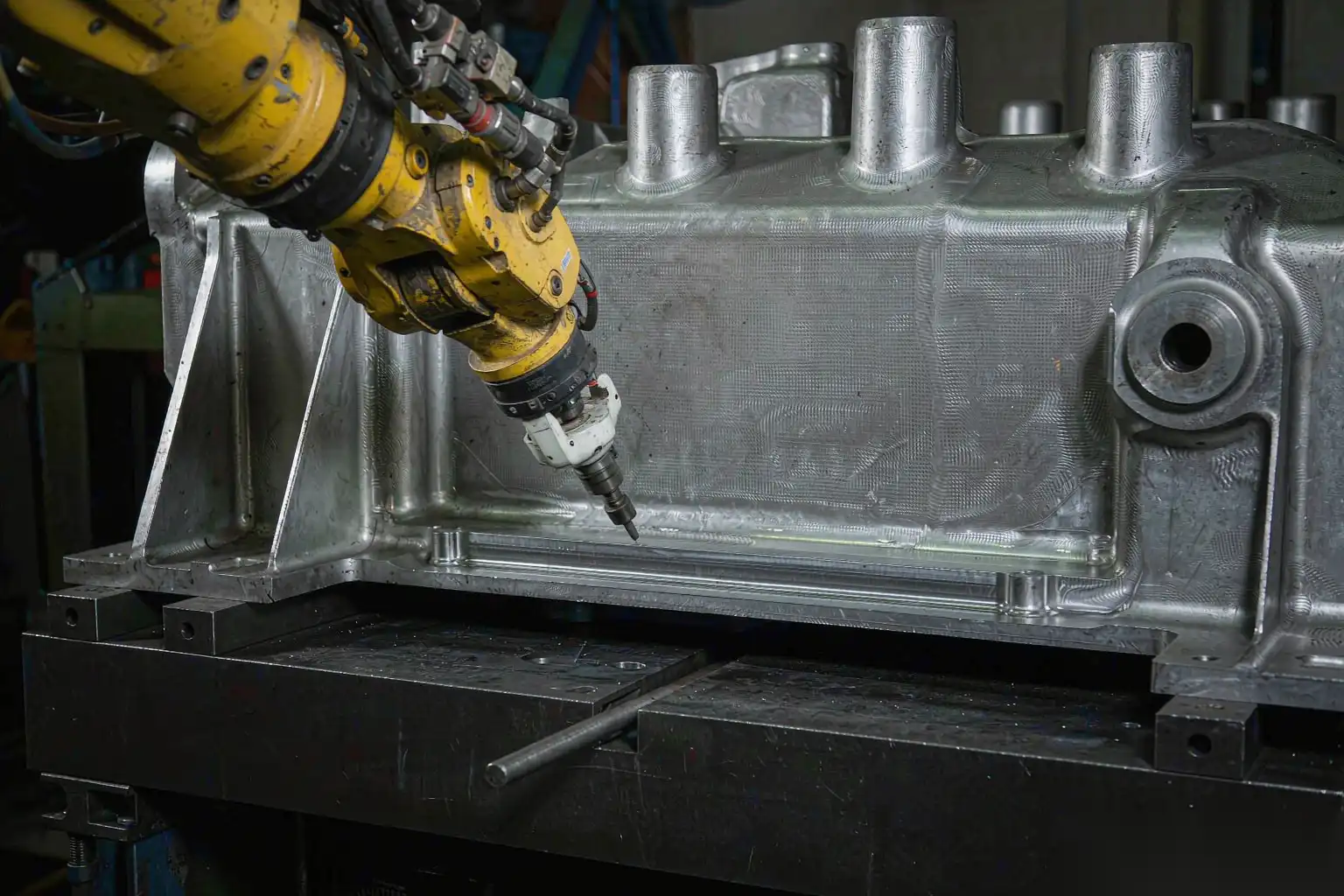
- Gate and biscuit removal. On a large tray the biscuit can be 8-15 kg and the runner runs the full perimeter. Manual cutting of that volume is slow, inconsistent and a genuine safety hazard. Robotic cutting with a saw or spindle, on a six-axis handler with the part fixtured, gives repeatable remnant height, typically within plus or minus 0.3 mm, and removes a labour-intensive step.
- Sealing-surface edge break. Every machined sealing face and every fastener hole needs a controlled, consistent edge break. A burr of 0.1 mm on a gasket flange is a leak path. The acceptance is normally a maximum burr height of 0.05 mm with a minimum edge break of 0.1 mm, which means the process has to hold both ends of a band, not just remove metal.
- Consistency is the requirement, not speed. A human can finish one housing well. The issue is that the two-hundredth housing of the shift, finished at 03:00, needs to be identical to the first. Force-controlled floating spindles with automatic tool change hold contact force constant as the abrasive wears, and part presentation on a dedicated fixture makes the result repeatable.
- Cooling interface surfaces need the same discipline. Any scratch or ridge on a cold plate mounting face defeats the thermal interface material.
- Chip and dust control. Aluminium fines from a tray-scale operation are a real volume, and the extraction system has to be rated for it with appropriate ATEX-classified components. Swarf carried into a leak test or into a pack assembly area is a contamination problem.
- Typical cell parameters for a 1.4 m tray: cycle time 90-180 s covering gate removal, perimeter deburring, flange edge break and hole deburring, with automatic abrasive change on a defined part count and force traces logged per part for traceability.
- Inspection integration. Burr height gauging immediately after the cell, before the part leaves the station, converts a latent defect into an immediate signal.
We build these cells at DZ Machinery with force-controlled floating spindles, pneumatic and floating belt heads, automatic tool change and multi-station turntables, together with the fixture design, extraction and safety enclosure. The same platforms are used for large die cast enclosures where flatness and edge consistency matter, and the general aluminum die casting finishing options discussion covers where each process fits.
If you are specifying a battery housing programme and want the gate removal and sealing-surface deburring step validated against your leak test acceptance level rather than treated as a final clean-up operation, send us the tray drawings, takt time and burr specification and we will quote the cell against those numbers.