Ejector Pin Marks on Die Castings: Causes and Practical Fixes
Why Ejector Pin Marks Appear
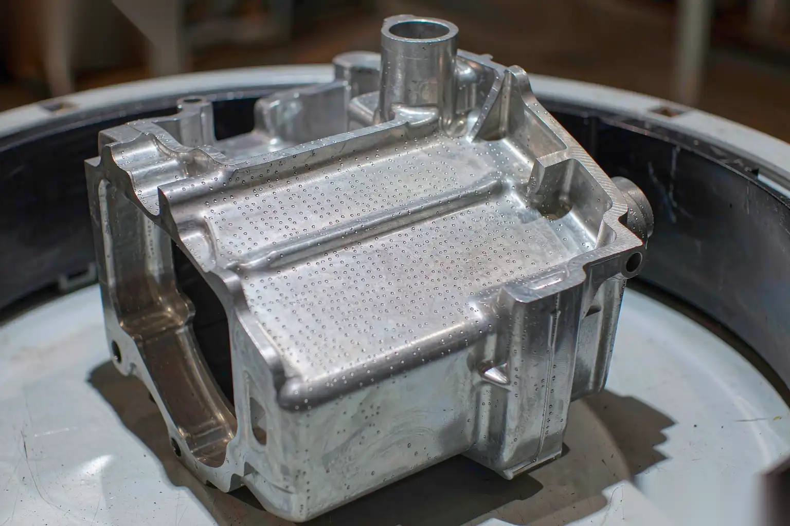
An ejector pin mark is the signature left where the pin pushed the solidified part off the core or out of the cavity. Every die-cast part is stripped by pins (or sleeves, or a stripper plate), and every pin contact leaves some trace. The trace becomes a defect when it is deeper than the part can spare, or when it sits on a face that must stay clean. The root cause is almost always force: the part will not release freely, so the pins have to push hard, and hard pushing deforms the local metal.
We separate the three causes because the fix differs for each:
- Ejection force too high: the part is gripping the core because draft is low, the core is long, or the alloy shrink-fit is large. The pins must apply high load, and the local metal yields under the pin tip. This is a draft and geometry problem first.
- Pin placement wrong: the pins sit where the wall is thin, where a rib meets a wall, or where the section is already stressed from fill. The same force that would be harmless on a solid boss dents a thin web.
- Pin design wrong: the pin is too small for the load, worn, or not backed by enough support, so it sinks into the part instead of pushing it. A 6 mm pin asked to carry a force meant for a 10 mm pin leaves a deeper, wider mark.
The interaction with draft is the one we control first. In the draft angle rules article we showed that more draft means less ejection force means shallower marks. On a new tool, if marks appear, the first question is whether the core was cut to the drafted angle on the drawing or under it; a core 0.3° under spec will mark even with good pins.
We also see marks driven by process, not geometry. A die running hot, or a part ejected before it is fully solid at the core, is soft and dents easily; a part held too long and shrunk tight also needs more force. Ejection temperature is a tuned parameter, not a fixed number, and we check it before changing pin layout.
Mark Classification: Dent, Smear and Scuff
Not all marks are equal, and the fix depends on the type. We classify three:
Dent
A dent is a local depression where the pin pushed the metal in. It is plastic deformation, not a surface smear. Dents are round or pin-shaped, measurable by depth with a dial indicator or a profilometer, and they do not rub off. A dent under 0.05 mm on a non-cosmetic face is usually accepted; a dent on a cosmetic or machined face is a reject if it exceeds the finishing stock.
Smear
A smear is a thin layer of metal pushed sideways by the pin, often with a raised lip at the edge. It happens when the pin face is not flat, when the pin is tilted, or when the local metal is soft at ejection. A smear is worse than a dent for finishing because the raised lip must be ground, and the smeared metal can fold over a cosmetic face and show as a flow-like line after polishing.
Scuff
A scuff is a dragged mark where the part slides against the core as it strips, leaving a streak of disturbed surface. Scuffs point to low draft, a sticking core, or inadequate lube; they run along the pull direction and can cover a wide band, not just the pin point. A scuff on a cosmetic face usually means the whole wall needs more draft or the core needs re-texturing.
Classification method we use on a rejected part:
- Section or profile the mark to see if it is a depression (dent), a lip (smear), or a directional streak (scuff).
- Measure depth against the finished-face stock; if the mark top is within the stock, the finishing cell can remove it, and the defect is a finishing-cost issue, not a reject.
- If the mark exceeds stock or is a smear lip on a visible face, it is a tool or process reject, and we fix upstream.
This step matters because shops often blame the polisher for marks the polisher can actually remove, or accept marks the polisher cannot. The surface finish standards define how much stock is allowed at each specified face, and that stock is the line between “mark” and “reject.”
Relocating and Resizing Pins
When the mark is a dent from too much local force, the first fix is to spread the force. A pin at a thin web dents; the same total force shared by two pins on a stiffer section does not. We relocate and resize by these rules:
- Move pins off thin walls and ribs onto adjacent solid bosses or thicker sections within 10-15 mm of the stuck zone, so the push is still effective but the bearing area is stronger.
- Add pins rather than enlarge one; three 8 mm pins spread force better and mark less than one 12 mm pin in the same spot, because they engage more of the part’s stiff structure.
- Enlarge pins only where the section allows; a bigger pin needs more platen travel and more clear steel around it, and it leaves a bigger scar to finish.
- Keep pin tips flush with the cavity at shutdown; a pin proud of the surface leaves a raised pip, a pin recessed leaves a dent and a step the finisher must grind.
We also check pin support. A pin with too little guide or a worn return shows tilt marks (smears); a pin that has lost its spring or its backing sinks. Pin maintenance is part of the tooling plan, and a worn pin set is a common late-life cause of marks that were not there at first article.
Placement also affects the finishing path. Pins on a face the robotic cell can reach are fine; pins buried in a pocket the spindle cannot enter leave a mark the cell cannot remove and the part is rejected at inspection. We put pins on reachable faces wherever the geometry allows, and we mark pin locations on the finishing program so the cell plans the pass.
The table below is how we size pins against load for aluminum at a typical ejection temperature:
| Pin diameter (mm) | Max safe load (kN, approx.) | Local bearing stress (MPa) | Preferred location | Mark risk if overloaded |
|---|---|---|---|---|
| 4 | 1.5-2.0 | 120-160 | Solid boss only | High dent |
| 6 | 3.5-5.0 | 120-180 | Boss or thick wall | Moderate dent |
| 8 | 6-9 | 120-180 | Wall or rib base | Low dent |
| 10 | 10-14 | 120-180 | Thick section | Low, but big scar |
| Sleeve (12-20) | 15-30 | Lower, distributed | Around core | Lowest, best for cores |
These loads assume a polished core and adequate draft; with low draft or texture, cut the safe load by 30-50%.
Using Ejector Sleeves for Cores
When the mark is on a core, the fix is often to stop pushing the part off the core and instead push the core through the part, or push a sleeve that supports the part while the core retracts. An ejector sleeve is a tube around the core; the sleeve advances and strips the part off the core while the core stays put or retracts slightly. The load is spread over the sleeve’s full circumference instead of a point, so the local mark is far shallower and often invisible.
We specify sleeves when:
- The core is long and the part grips it hard; point pins dent the base of the boss.
- The feature is a deep hole or boss that must stay round; a sleeve keeps the bore true while stripping.
- The part is cosmetic on the cored face; the sleeve leaves a clean ring, not a pin dent.
Sleeves add cost: a sleeve needs its own guide, its own return, and close fit to the core to avoid flashing a ring. But on a deep cosmetic boss they are cheaper than scrapping parts for marks across a long run. We size the sleeve wall so it carries the strip load without deflecting into the core, and we confirm the sleeve’s parting leaves a flash line the deburring cell can reach.
A stripper plate is the larger version of the same idea: a plate that pushes the whole part off the cavity at once, spreading force over the entire parting face. We use stripper plates on flat parts with many thin features where individual pins would mark or bend the walls. The cost is a second moving plate and more die height, but for a thin-wall panel it removes marks that pins cannot.
Surface Prep So Automated Polishing Removes Residual Marks
Most ejector marks are not rejected; they are finished. The job of the upstream tool and process is to keep marks within the finishing stock, and the job of the robotic polishing cell is to remove them consistently. We prepare the part so the cell succeeds:
- Keep marks under the specified stock. A cosmetic face finished to Ra 0.8 after 0.10 mm removal can absorb a 0.08 mm dent; a 0.15 mm dent cannot and is a reject. Draft and pin area set this.
- Keep marks on reachable faces. A mark the spindle or belt cannot touch is a reject regardless of depth. We place pins with the finishing path in mind.
- Avoid smear lips. A smear folds metal over the face and the polisher opens a line; flat, flush pins and correct ejection temperature prevent smears better than any polishing program.
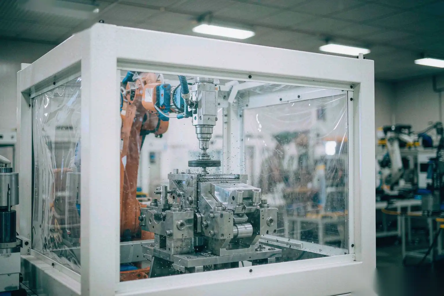
The robotic polishing cell we build handles residual marks as part of the normal pass. A robotic deburring and grinding automation cell with force control follows the part surface and removes the shallow dent in the same pass as the parting-line flash, holding the stock to the spec. Where marks are deeper or on a tighter face, we add a second polish stage with a finer media, and we set the stock so the mark clears without over-grinding the surrounding face (over-grinding changes the contour and can break flatness).
We verify the cell removes marks by measuring before and after on a sample set:
- Profile the mark depth on 10 parts before finishing.
- Run the cell at the quoted parameters.
- Profile the same faces after; confirm marks are within the finished-face tolerance and no new contour error was introduced.
- Lock the parameters only after this passes; a cell tuned to remove flash but not marks will drift once production volume rises.
The link to defect classification is direct: the aluminum die casting defects and solutions view treats ejection marks as a controllable process defect, and the polishing cell is the last line that converts a controlled mark into an acceptable surface.
When Marks Become a Cosmetic-Class Reject
A mark crosses from “finished” to “reject” at the point where it exceeds the finishing stock on a face that must stay clean, or where it is a smear or scuff that the polish opens into a visible line. We set the reject threshold on the drawing, not on the floor, because an undefined threshold is argued over every shift.
The reject rules we document:
- Cosmetic face, specified stock 0.10 mm: any dent deeper than 0.10 mm, any smear, any scuff = reject.
- Non-cosmetic structural face: dents under 0.15 mm accepted if they do not break wall thickness or function; deeper = review.
- Machined face: mark within the machining allowance is removed by CNC; mark below the allowance = reject because the machined face would show it.
- Sealing face: any mark that breaks the seal band = reject, because leak test will fail regardless of polish.
The cost of a reject is not just the part; it is the lost finishing minute and the inspection load. We therefore bias the tool design toward marks that are always finishable: enough draft, enough pin area, sleeves on cores, reachable pin faces. The downstream cell then runs at a stable yield instead of fighting variable marks part to part.
When a batch shows rising marks, the diagnosis order is: check ejection temperature (soft part dents), check draft actually cut (under-spec core binds), check pins (worn, tilted, recessed), then check process (hot die, late ejection). We fix in that order because it moves from cheapest to most expensive, and most mark problems are ejection temperature or worn pins, not the original tool design.
The DZ Smart Manufacturing engineering team designs ejector pin layout, sleeves and the robotic polishing cells as one package, so marks are held within the finishing stock by the tool and removed consistently by the cell from the first run. If you are seeing ejection-mark rejects or high polishing cost, send us the part model and a few samples and we will map the marks and return a pin, sleeve and finishing proposal together.