Aluminum Die Casting Draft Angles: Rules, Lifters and Undercuts
Minimum Draft by Surface Texture
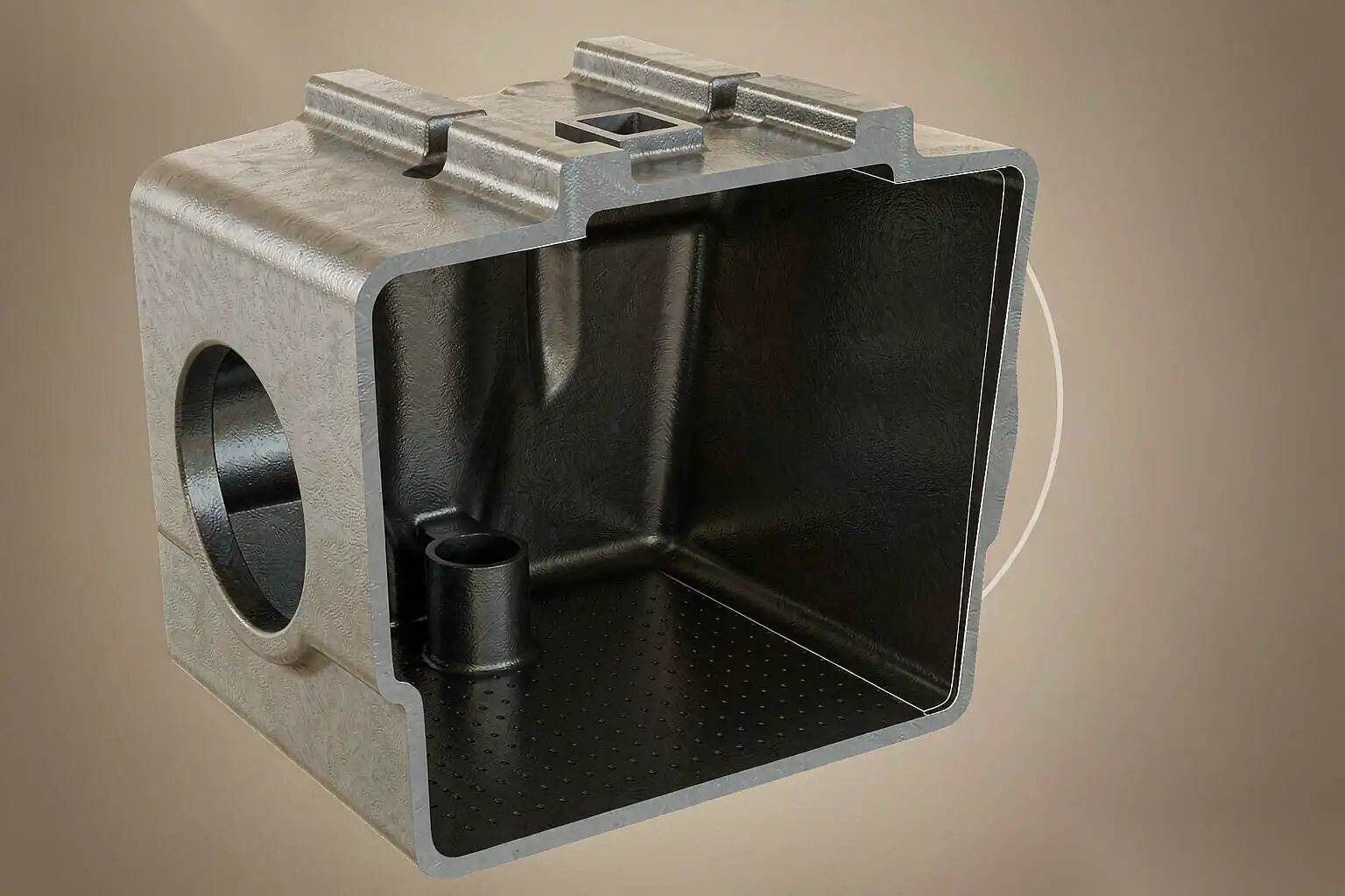
Draft angle is the taper on a mold wall that lets the solidified part leave the cavity or core without scoring the steel or tearing the part. In aluminum die casting the minimum draft is not a single number; it depends on how the steel surface was finished, because the surface texture sets the friction and the mechanical interlock at ejection. A polished core releases at a much lower angle than a textured or bead-blasted one.
We use the following minimum-draft starting points for aluminum (A380, A360, A356 class alloys):
| Steel surface condition | Minimum draft on cavity wall | Minimum draft on core (internal) | Why |
|---|---|---|---|
| Polished, under 0.2 µm Ra | 0.5° | 1.0° | Low friction, but internal walls need more for safe strip |
| As-machined, 0.4-0.8 µm Ra | 1.0° | 1.5° | Tool marks add grip |
| Fine bead-blast / stone | 1.5° | 2.0° | Texture interlocks with alloy |
| Coarse textured / EDM matte | 2.0-3.0° | 2.5-3.0° | Deep texture needs real taper |
These are launch values, not absolutes. The actual required angle rises with wall length, because a long wall accumulates more total interference as the part shrinks onto the core. A 1.0° draft on a 10 mm deep core may release; the same 1.0° on a 60 mm deep core may bind because the cumulative shrink clamping force grows with length. For deep cores we add draft per the formula that total interference equals shrink rate times depth times tan(angle), and we size the angle so that interference stays below what the ejector force can overcome without marking.
Texture also interacts with cosmetic intent. A part that must look textured after casting needs a textured die, which forces a higher draft; if the customer also wants crisp detail, we move the texture to a non-ejection face or accept the larger angle in the tool quote. Draft is a die cost and a part geometry decision made together, not a number filled in after the shape is fixed.
How Draft Interacts With Thin Walls and Deep Cores
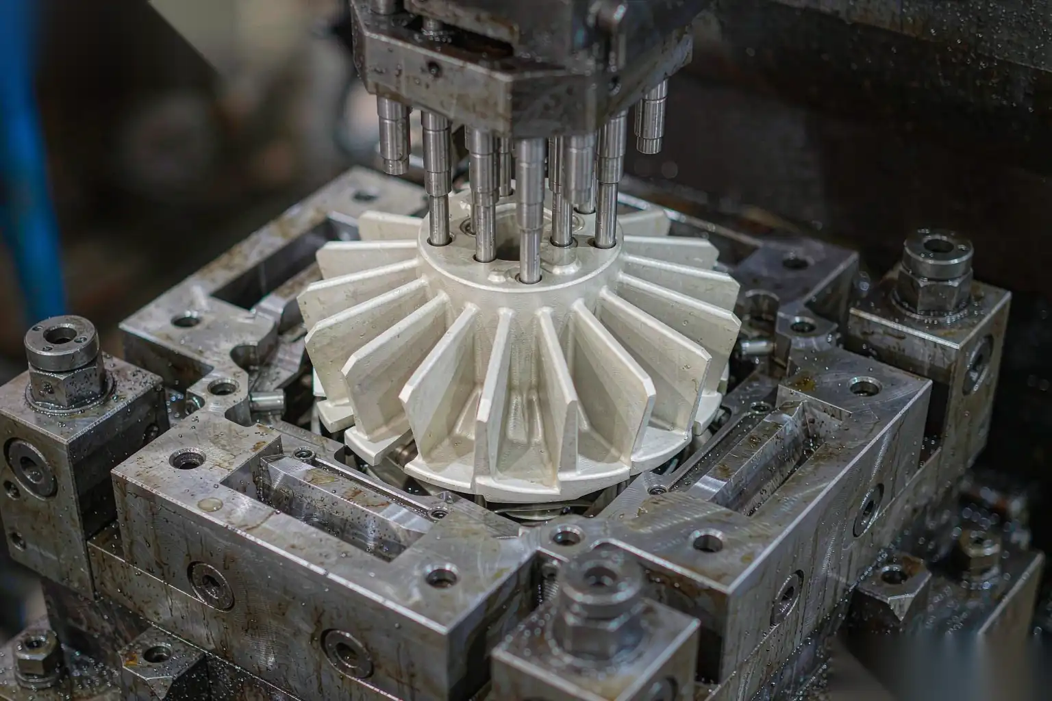
Thin walls are the parts most sensitive to draft, because they are also the parts most likely to be long, deep, or both, and they have the least material to absorb ejection stress. A 1.2 mm wall with 1.0° draft on a 50 mm core has very little section to resist bending as the ejector pushes it off the core. If the draft is too low, the wall wipes or buckles instead of sliding.
The interaction we watch:
- Thin wall plus low draft: the wall starts to bend before it releases, leaving a scuff or a permanent set (the part comes out slightly curved). We raise draft or shorten the core.
- Thin wall plus deep core: shrink onto the core is large in absolute terms even at low shrink rate, so required draft climbs. A 0.8° minimum may become 1.5° in practice.
- Thin wall plus long flow path: the wall may not have filled evenly, and a thin, cold section breaks at ejection. Draft cannot fix a fill problem; that is a flow simulation issue first.
For deep cores we also separate internal draft (the core taper) from external draft (the cavity wall taper). Internal draft is always the harder release because aluminum shrinks onto the core, so we give internal walls 0.5° more than external as a default unless simulation or trial says otherwise. Where a deep core cannot carry that extra taper for function, we add a lifter or a strip, discussed below, rather than force a low draft and accept ejection marks.
The thin-wall design guidance and draft are linked: thin-wall parts succeed when draft, wall thickness and core depth are set as one constraint set at the drawing stage, not negotiated after a first tool trial fails.
When to Add Lifters or Slides Instead of Forcing Draft
A draft angle cannot fix a true undercut or a net-negative-taper wall. When a feature runs opposite to the parting direction, no amount of taper on the main cavity helps; you need a moving element. The choice is between a lifter (a small core that moves with the ejector plate, usually at an angle) and a slide (a core pulled sideways by the machine’s hydraulic or cam action before ejection).
We decide by geometry and frequency:
- Undercut on an internal wall, small, near the parting line: a lifter. It travels with ejection, clears the undercut, then retracts. Cheap, compact, but limited in size and in how much side load it takes.
- Undercut on an external face, large, away from the parting line: a slide. The slide pulls before the part moves, leaving a clean wall at any draft you choose, including near-zero if the function needs it.
- Threaded boss or ring feature: often a rotating core or a collapsed core, since a slide cannot clear a full circle.
- Deep side pocket: a slide with a heel block for clamping, because the injection pressure pushes the slide open and it must be locked.
The cost trade is real. A slide adds a cam, a heel, a hydraulic line or a horn, and a maintenance point; a lifter adds a guided element in the ejector plate. Both are cheaper than scrapping parts from a forced-low-draft ejection failure, but both add tool cost and cycle time. We specify the moving element in the tool quote with its stroke, clamp and maintenance interval, and we confirm it does not collide with the robotic finishing path (a slide parting line is a flash seam the deburring cell must handle).
A common error is designing a feature with “0° draft because it is functional” and expecting the tool to eject it. If the wall is a true negative relative to pull direction, you must add a lifter or slide; draft alone will not release it. If the wall is only low-draft (say 0.3° on a polished core), you may get away with it on a short core but you are betting ejection marks against tool cost, and we document that bet explicitly.
Draft and the Ejection-Force Relationship
Ejection force is what strips the part off the core, and draft is the lever that reduces it. The required force scales with the contact area, the shrink-fit pressure, and the friction coefficient, and it falls as draft increases because a larger angle converts more of the ejector push into a separating normal force and less into sliding friction. Roughly, doubling the draft from 0.5° to 1.0° on a polished core can cut the required ejector force by a meaningful fraction; going from 1.0° to 2.0° cuts it further but with diminishing return and a geometry penalty.
We estimate ejection force at the quoting stage:
- Compute shrink-fit: aluminum shrinks about 0.5-0.7% on the core from solidification to ejection temperature, so a 40 mm core gains roughly 0.2-0.3 mm of interference around its circumference.
- Multiply by the core wall contact area and the alloy’s yield at ejection temperature to get the clamping load.
- Divide by the friction coefficient (lower for polished steel and for a die lube film, higher for textured steel) to get the sliding force.
- Add the force to bend or strip any thin wall, and compare to the pin count and area available.
If the force exceeds what the pins can apply without exceeding the part’s local compressive strength, we either raise draft, add pins, enlarge pins, or add a lifter to take the side load. The limit we watch is pin bearing stress: a 6 mm ejector pin on A380 at ejection should stay under roughly 150-200 MPa local bearing to avoid sinking the pin into the part. Too few pins at too low a draft means each pin overstresses and leaves a dent, which is exactly the ejection-mark problem covered in the ejector pin mark solutions article in this batch.
Draft and ejection force are the same decision seen from two sides. More draft means less force means fewer or smaller pins means fewer marks. We treat draft as the first control on ejection marks, before we touch pin layout.
Ejection Marks, Draft and Finishing Cost
Ejection marks are the visible dents, smears and scuffs left where the pins pushed the part off the core. Draft is the upstream control: enough draft means low ejection force means light pin contact means shallow marks. When draft is forced low to hold a geometry, the pin force rises and the marks deepen, and the finishing cell has to remove them.
The finishing cost link is direct:
- A shallow dent (under 0.05 mm) on a non-cosmetic face: the robotic grinding cell takes it in the normal flash-removal pass, no extra cost.
- A smear or scuff on a cosmetic face: needs a dedicated polishing pass, and if it is below the polishing stock it becomes a reject.
- A deep dent that the part cannot spare stock to remove: a cosmetic-class reject at final inspection.
We set the drafting and pin rules so that marks stay within the finishing stock. For a part finished to Ra 0.8 after 0.10 mm of stock removal, ejection marks deeper than 0.10 mm on a finished face are rejects; the tool must therefore carry enough draft and pin area to keep marks under that depth. This is why we design draft with the finishing stock in hand, not in isolation.
The flatness control of the part also depends on even ejection. If one side has low draft and high force, the part deflects as it strips and comes out warped; the robotic cell then grinds uneven stock and the flatness drifts. Even draft and even pin force produce even release and hold flatness, which keeps the finishing pass uniform.
Practical drafting checklist we use before steel is cut:
- Assign every wall a pull direction and a draft class (polished, machined, textured).
- Set external draft 1.0° minimum, internal draft 1.5° minimum, raised for texture per the table.
- Flag any wall under 0.5° as a risk; require a lifter, slide, or written acceptance of ejection marks.
- Confirm deep cores get 0.5° extra or a moving element.
- Map finished faces and their stock; require marks to stay under that stock via draft and pin area.
- Run an ejection-force estimate and confirm pin bearing stress is in range.
Draft Rules for the Tool Drawing and Production
Draft is only useful if it is on the drawing, controlled at the steel, and checked in production. We put draft into the tool specification as a dimension, not a note, because a note gets ignored. The cavity and core are then measured at first article to confirm the machined angle matches the spec; a core cut 0.3° under spec will bind and mark parts even if the drawing was right.
In production, draft effectiveness changes as the die wears and the steel textures from use. A polished core that releases at 0.5° may need 0.8° equivalent after 100,000 shots because the surface has roughened and picked up lube residue. We track ejection force through the machine’s process data; a rising force at fixed plunger and fixed pin layout signals the draft is effectively shrinking and the die needs maintenance or the lube needs adjustment. The mold design guide covers the full cavity and core specification, of which draft is one controlled parameter alongside the gating and cooling.
For the customer, the message is simple: draft is free insurance. Adding 0.5° to a wall rarely changes function but routinely cuts ejection marks, finishing cost and warpage. When a geometry truly cannot carry draft, tell us early so we design the lifter or slide into the quote instead of discovering it after the first trial fails and the parts come out marked.
The DZ Smart Manufacturing engineering team designs draft, lifters and the robotic deburring and polishing cells as one system, so the draft angles and pin layout are set with the finishing stock and the polishing path in view from the first tool drawing. If you have a part that marks at ejection or costs too much to finish, send us the model and we will return a draft and ejection proposal together with a finishing-cell estimate.