Die Casting Die Lubrication and Spray: Film Behaviour, Defect Tracing, and Cycle Time Cost
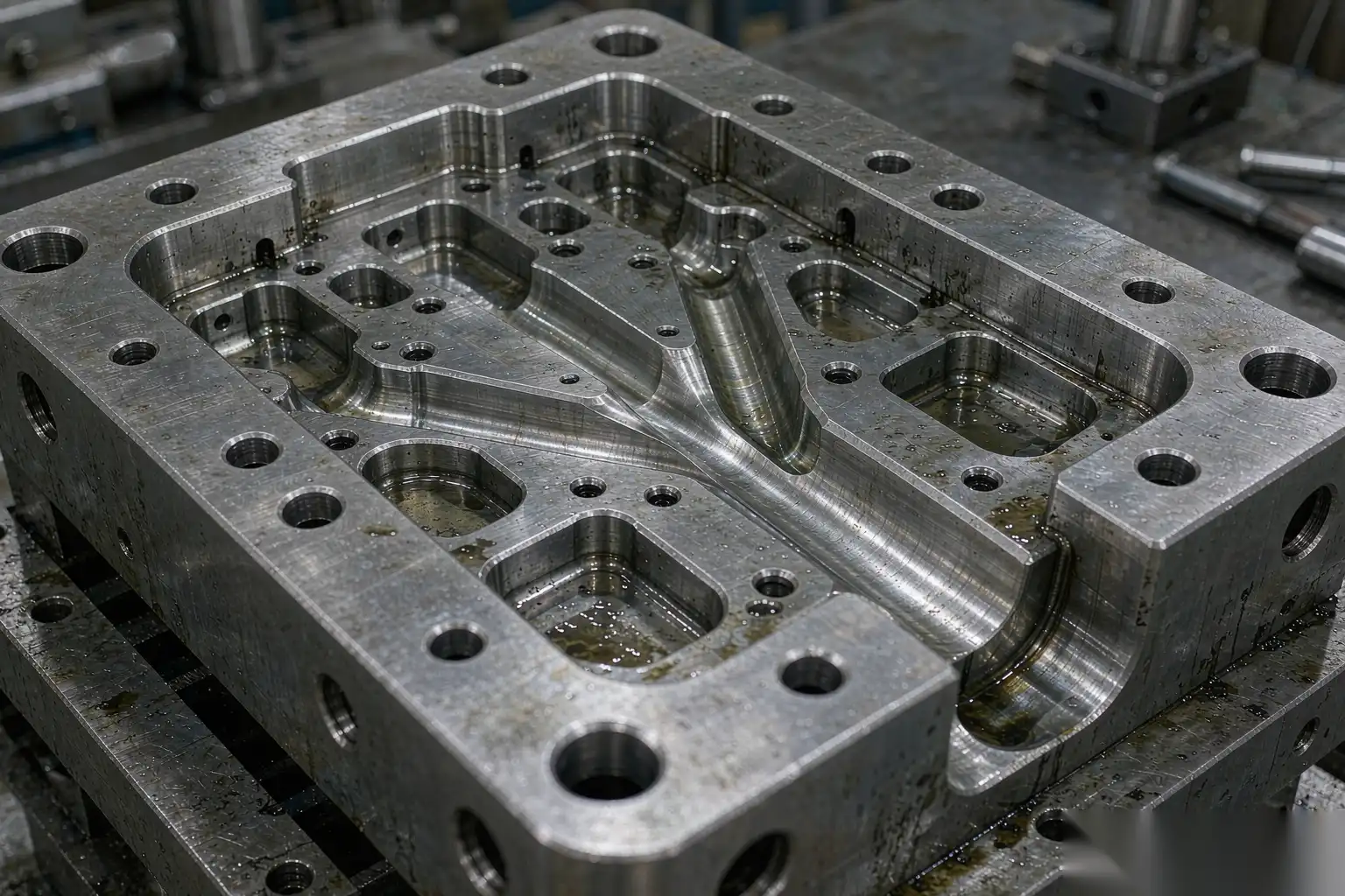
Die spray is treated as housekeeping on most die casting floors. It is run on a timer, adjusted by whoever is standing at the machine, and discussed only when parts start sticking. Meanwhile it consumes 15 to 30 percent of the quoted cycle time, it decides whether your castings pass a leak test, and it governs whether cosmetic parts arrive at the finishing cell with a clean surface or a carbon deposit that eats polishing belts.
This is written from the finishing and productivity side of the plant. We see the symptoms at the grinder and the polisher, and by the time a defect shows there it is already expensive. Understanding what the spray film is supposed to do makes it much easier to diagnose why parts have gas porosity, why they drag in the cavity, or why the robot cell has to add a step.
Covered below: the three real functions of the film, lubricant types, dilution control with numbers that survive contact with plant water pressure, delivery methods from handheld lance to pulse-spray manifold, the spray parameters that create specific defects, a defect tracing table, cycle time accounting, and finally why die temperature management rather than release is the real objective.
What the Lubricant Film Actually Does
A die lubricant is doing three jobs at once, and they are in tension with each other.
- Release. A thin barrier film on the cavity surface prevents aluminium alloying with and mechanically keying into the die steel. Without it you get soldering: aluminium bonds locally to the die, tears out on ejection, and progressively damages both casting and tool. Release is usually the reason people buy lubricant, but it is the least demanding of the three jobs.
- Thermal control. The dominant job. Every shot dumps roughly 300 to 400 kJ per kilogram of metal into the die before the casting drops below the extraction temperature. For a 2 kg shot that is 600 to 800 kJ per cycle, which at a 40 s cycle is a sustained 15 to 20 kW of average heat load that has to leave the tool. Spray removes part of that load by evaporation and sensible heating of water; internal cooling lines remove the rest. Getting the split wrong is what produces thermal cracking and dimensional drift.
- Protection and lubricity. The film reduces the erosive effect of high velocity metal on the die surface, particularly at the gate and at cores. Separately, and often confused with this, the shot sleeve and plunger tip require their own lubrication regime, because a dry tip scores the sleeve and introduces air into the shot.
The tension is straightforward: more film gives better release and worse porosity, or better cooling and more cycle time. Every parameter you set is somewhere on that trade-off surface, which is exactly why the process should have a written window rather than a habit.
Lubricant Types and Where Each Belongs
| Type | Composition and typical solids | Dilution or form | Where it belongs | Limitations |
|---|---|---|---|---|
| Water-based emulsion | Wax, polymer or synthetic ester in water; concentrate solids 10 to 40 percent | 1:60 to 1:200 by volume with water | The default for HPDC cavities; correct choice for nearly every aluminium application | Requires correct dilution and clean water; too much water means porosity risk |
| Water-based synthetic, wax-free | Polymer or silicone-free synthetic packages | 1:80 to 1:250 | Where downstream painting or plating must not see wax or silicone residue | Often lower film strength, more sensitive to hot spots |
| Silicone-containing systems | Silicone emulsion, sometimes blended | 1:100 to 1:400 | High-temperature cores, difficult release geometry | Silicone residue causes fisheyes and adhesion failure in paint and powder coat; keep it out of any line that coats downstream |
| Powder / dry lubricant | Powdered solids applied electrostatically or pneumatically to the warm die | No dilution | Where water must be eliminated entirely to avoid hydrogen pickup | Needs clean, dry die faces and good extraction; higher consumable cost; not yet mainstream in general jobbing shops |
| Oil-based or graphite systems | Graphite or oil suspensions, sometimes solvent-borne | Ready to use or light dilution | Historical use, now largely restricted to special cases and plunger-tip applications | Smoke, fire risk, die deposits, housekeeping problems; avoid in modern cells |
| Plunger and sleeve lubricant | Graphite-free synthetic or oil-based, applied at the pour hole or tip | Ready to use | The shot sleeve, never the cavity | Applying this in the cavity is a common and expensive mistake |
One hard rule worth stating: anything containing silicone should be qualified by the painter or plater before it enters the plant. We have seen whole batches of faucet bodies rejected because someone switched to a high-silicone lubricant to solve a soldering problem on one die, and the residue survived normal pre-treatment.
Dilution Ratio and How to Control It
Most spray-related defects we investigate trace back to concentration drift, not to the wrong product.
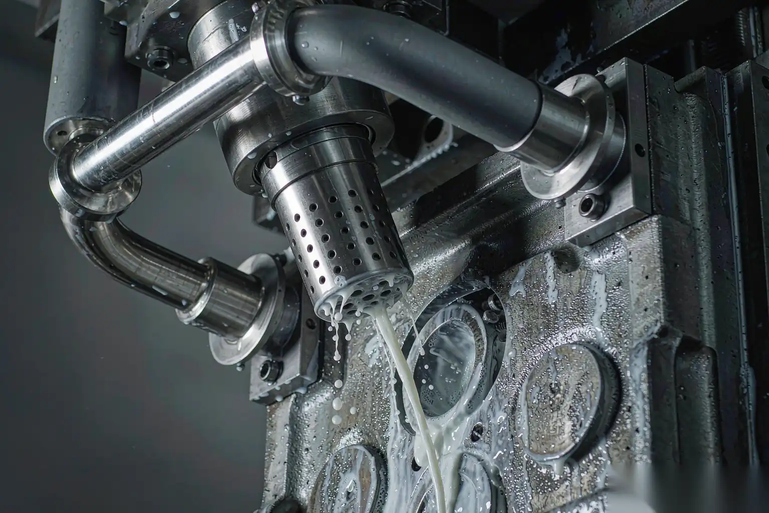
The mechanics are bad by default. The concentrate is usually metered by an injector or proportioning pump that depends on plant water pressure, and the operator’s corrective reaction to any problem is to turn the dial up. Three months later you are running 1:60 on a product specified at 1:150, gas porosity has crept up, and nobody connects it back.
What actually works:
- Mix centrally. A single proportioning station feeding all machines, with a recirculation loop, removes per-machine variability and makes one person accountable. It also allows you to check one number instead of twelve.
- Verify with a refractometer, not by eye. Establish the Brix reading at the qualified concentration for each product and record it every shift with a ±10 percent action limit. A refractometer costs very little and will pay for itself the first time it catches a proportioner failure.
- Use positive displacement dosing where possible. Injectors drift with pressure; dosing pumps and flow meters do not. If you must use injectors, install a pressure regulator upstream and a flow meter on the concentrate line.
- Control the water. Total hardness in the 50 to 150 ppm range and inlet temperature between 20 and 40 °C. Very hard water reacts with the emulsifier package and causes instability; very cold water increases viscosity and changes metering behaviour between winter and summer.
- Label mixed containers with date and product. Re-circulated emulsion supports microbial growth, which causes odour, filter blockage, and nozzle fouling. If you recirculate, treat with biocide on a schedule and clean tanks monthly.
- Keep the concentrate temperature stable. Product stored outdoors in winter changes viscosity enough to shift dosing by 20 percent or more.
For a product specified at 1:150, the working instruction should read something like: refractometer target 4.2 °Bx, action band 3.8 to 4.6 °Bx, check at shift start and after every batch make-up, record. That is a checkpoint a quality system can audit.
Spray Delivery: From Hand Lance to Pulse Spray
| Delivery method | Typical consumption per shot | Repeatability | Capital | Best application |
|---|---|---|---|---|
| Manual hand lance | 10 to 40 L, operator dependent | Poor, varies with the person and the shift | Very low | Start-up, sample shots, very short runs only |
| Fixed manifold bolted to die halves | 5 to 25 L | Good, if nozzles are never moved | Low | Stable, high volume parts with simple geometry |
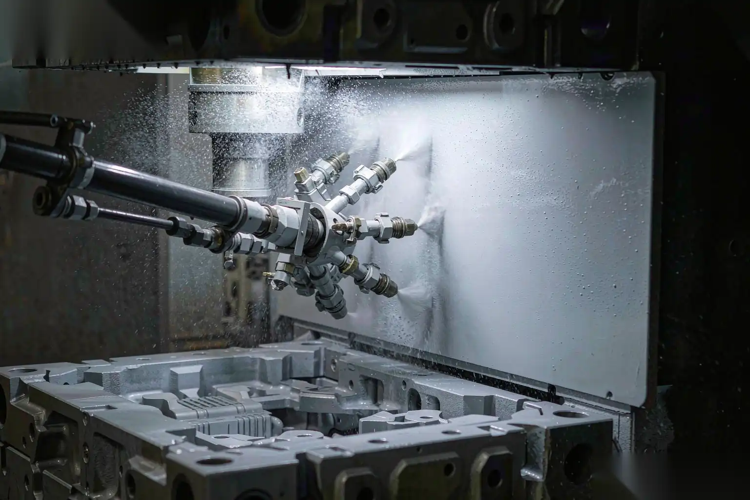
| Reciprocator-mounted spray tree | 3 to 15 L | Good; adjustable pattern and dwell per zone | Medium | The usual upgrade path for existing cells |
| Micro-spray / metered pulse manifold | 0.1 to 1.5 L | Very good | Medium to high | High volume parts where spray time is significant in the cycle |
| Robotic spray with taught paths | 0.2 to 2.0 L | Excellent, including complex cores and deep pockets | High | Large dies, complex geometry, frequent changeovers |
The consumption difference is worth stating plainly because it changes several things at once. Going from a flooding manifold at 12 L per shot to a micro-spray manifold at 0.8 L per shot usually cuts spray time by 40 to 70 percent, cuts water treatment load proportionally, cuts wastewater volumes, and reduces how much water enters the runner system. The common objection is that less liquid means less cooling; that is only true if the evaporation efficiency was high to begin with, which on a flooding manifold it usually is not, because most of the water simply runs off the die and into the pit.
Target film behaviour
What you want at the die face, regardless of delivery method:
- Droplets arrive with enough momentum to penetrate the vapour layer that forms on a hot die surface.
- They wet out, spread, and boil off within roughly 0.5 to 3 s of contact.
- What remains is a thin, continuous dry film in the 2 to 10 µm range.
- Nothing runs, pools, or drips when the die closes.
The physics that makes this hard is the Leidenfrost effect. Above roughly 220 to 250 °C surface temperature, water droplets do not properly contact the steel; they ride on their own vapour cushion and roll off without transferring much heat. Since die faces routinely run at 180 to 260 °C, a large part of the spray could be doing nothing at all. The practical fixes are finer atomisation, higher droplet velocity through air-assisted or airless atomising nozzles, and staging so that the die surface has partly cooled by the time the bulk of the spray arrives. Simply adding more water rarely helps.
Spray Parameters That Drive Defects
These are the parameters worth putting into a work instruction with numbers and tolerances.
- Atomising air pressure: 2 to 6 bar. Higher gives finer droplets and better penetration of deep features, but also blows film off nearby surfaces and increases air consumption, which is a real energy cost.
- Fluid pressure: 0.5 to 4 bar. This sets flow rate; in most plants it is the knob operators abuse first.
- Nozzle-to-die distance: 100 to 300 mm, with spray cone angles of 15 to 60 degrees. Outside that band you lose either coverage or transfer efficiency.
- Spray time: 0.8 to 6 s for micro-spray, 2 to 15 s for conventional systems.
- Blow-off and dry time: 0.5 to 4 s of clean air after spray. Skipping it is one of the most common causes of gas porosity, because trapped water in pockets and ejector clearances goes into the next shot.
- Volume per shot: record it. Install a flow meter on the manifold. If it changes, something changed.
- Sequence: spray the hotter core side first and for longer than the cover side in asymmetric dies. Uniform pulsing across every nozzle is a starting point, not an optimum.
Too much lubricant produces
- Gas porosity. Water reaching molten aluminium dissociates: aluminium plus water gives alumina and hydrogen, and that hydrogen enters solution and precipitates as round pores. Pores from this mechanism are characteristically round and smooth-walled, unlike shrinkage porosity, and they frequently cluster opposite the last spray areas or near ejector pins where water pools. See aluminum die casting porosity causes solutions for how that interacts with other porosity mechanisms.
- Lube kick residue. Black or brown deposit in deep pockets and blind bosses, where water and solids collect and bake on over successive cycles.
- Poor fill and cold lap. Localised over-cooling chills the metal front in thin sections.
- Downstream finishing problems. Carbon deposit loads abrasive belts and breaks the wetting of polishing compounds, so the cell either runs slower or misses finish.
Too little lubricant produces
- Soldering. Aluminium bonds to the die surface. It starts as a dull spot and becomes a raised build-up that scores every subsequent casting. Once established it is self-accelerating.
- Drag marks and ejection damage. Parts leave the die with torn surfaces and bent features, which then have to be ground out.
- Thermal cracking. Local die temperatures above about 300 °C at the surface accelerate heat checking, particularly at gate areas and small cores.
- Short die life. Heat checking plus erosion is what actually kills a tool, and both start with localised overheating.
Tracing Defects Back to Spray
Diagnosis should be in one direction: from defect location to likely spray cause to a specific number to change. Change one thing at a time and record it.
| Symptom | Where it appears | Probable spray cause | First corrective action |
|---|---|---|---|
| Round pores clustered under one zone | Opposite the heaviest-sprayed die area | Too much volume, or insufficient blow-off | Reduce that manifold’s flow by 20 percent, add 1 s of dry time, re-check after 20 shots |
| Black deposit in pockets and bosses | Deep features, away from the gate | Pooling from over-spray; poor drainage | Reposition nozzles, add directed blow-off into the pocket |
| Silver streaks along flow direction | From the gate toward overflows | Chilled metal front from localised over-cooling | Reduce dwell in that zone; raise local die temperature |
| Soldering and drag on a specific face | The hottest face, often near gate or thin cores | Insufficient film, or blocked nozzle | Check nozzle condition and filtration first, then increase dwell 0.5 s |
| Casting sticking on ejectors | Around ejector pins | Build-up in pin clearances; over-spraying pin area | Reduce spray directed at pins, add targeted blow-off |
| Rework at grinding for parting line | Perimeter of the part | Usually not spray; check die mismatch and tie-bar condition | Verify trim and die condition before touching spray |
Note the last row deliberately. Spray gets blamed for problems it does not cause, and changing it to chase a mechanical problem wastes days. For a broader diagnostic framework covering non-spray causes, refer to aluminum die casting defects and solutions.
Cycle Time Cost of Spray and How to Reduce It
Spray is usually the largest single controllable block of the die casting cycle after solidification dwell. A representative budget for a mid-size part on a 250 to 400 tonne machine:
| Phase | Typical seconds | Share of a 45 s cycle | Controllable |
|---|---|---|---|
| Die close and lock | 2.0 | 4 percent | Limited by machine |
| Ladle or auto-pour | 1.5 | 3 percent | Yes, automation |
| Injection and intensification | 0.5 to 1.0 | 2 percent | Yes, profile tuning |
| Dwell (solidification) | 12.0 | 27 percent | Limited by thermal balance |
| Die open and ejector | 2.5 | 6 percent | Limited by machine |
| Part take-out (robot or manual) | 6.5 | 14 percent | Yes, robot path and gripper |
| Die spray | 6.0 | 13 percent | Principal target |
| Blow-off and dry | 3.0 | 7 percent | Principal target |
| Miscellaneous and safety interlocks | 10.0 | 22 percent | Partly |
So about 20 percent of the cycle is spray plus dry. On a cell producing 60 parts per hour, saving 4 s of spray raises output to roughly 66 per hour, which is about 10 percent more capacity from equipment you already own. That payback typically beats every other capital project available to the plant.
How the seconds are actually recovered:
- Move from flooding to metered micro-spray. Typically 2 to 4 s saved, plus reduced water treatment cost.
- Zone control. Most dies do not need uniform coverage. Deep cores and hot spots need dwell; flat areas do not. Zone valves with independent timing usually save 1 to 2 s and improve consistency.
- Blow-off discipline. Directed knife-edge air rather than general blast dries faster at lower air consumption.
- Fix the nozzles. Worn nozzles are the most common hidden spray cost. A nozzle that has eroded from 1.0 to 1.3 mm passes significantly more flow at the same pressure, which quietly shifts every other parameter. Inspect and replace on a schedule, not on failure.
- Integrate with take-out. Overlapping robot extraction with the first part of the spray sequence removes 1 to 3 s without changing either operation.
Die Temperature Management as the Real Objective
Release is easy; thermal control is the hard part, and it is what ultimately limits sustainable cycle time. A die that cannot shed its heat will not run at the quoted rate regardless of how fast the machine can move.
Practical thermal discipline:
- Instrument the tool. Thermocouples 3 to 5 mm beneath the cavity surface in the gate area, at hot cores, and at the far fill end. Record every shot or every tenth shot. Trends matter more than absolute values.
- Target windows. Typical working die surface temperatures for ADC12-type alloys are in the 180 to 260 °C band, with variation across the die ideally under 50 °C. Below roughly 150 °C you will see flow-related defects; sustained above roughly 300 °C at isolated spots you will get soldering and accelerated heat checking.
- Measure the face directly. An infrared camera or pyrometer reading taken immediately after die-open gives you the real surface condition once per maintenance cycle. Doing this weekly catches cooling-line blockage and scale build-up months before it costs you dies.
- Know the heat balance. With roughly 300 to 400 kJ per kilogram entering the tool each shot, a 2 kg shot at a 40 s cycle is a sustained 15 to 20 kW load. Evaporating one litre of water at the die face removes around 2.5 MJ including sensible heating, so even modest effective evaporation matters enormously. The corollary is that any water running off instead of evaporating is wasted time, wasted energy, and wasted water treatment capacity.
- Balance lines before tuning spray. If the thermocouples say one region runs 80 °C hotter than another, no amount of spray adjustment will fix it. Fix the cooling circuit first.
The reason we care about this from the finishing side is that die temperature drives casting surface quality, and casting surface quality drives everything the robot cell has to do. A die running in its correct thermal window produces consistent skin thickness, consistent fill, and a predictable incoming roughness, which is what allows an automated cell to run at high yield rather than constant adjustment.
DZ Machinery designs robotic deburring, grinding and polishing cells around defined incoming part conditions, and we routinely review spray and die thermal practice with customers whose cosmetic yield is unstable. If your polishing line is fighting periodic carbon residue or variable surface roughness, send us the part drawings and a short run of sample castings and we will trace it back through the process.