Die Cast vs Wrought Aluminum: Microstructure, Property Envelopes and Where the Break-Even Sits
The question “die cast or wrought” is usually asked as a strength question and answered with a datasheet. That is the wrong frame. A cast A380 bracket and a 6061-T6 billet have overlapping tensile numbers, but they fail in completely different ways, they machine with different tool life, they respond to surface treatment differently, and above all they sit on opposite sides of a volume break-even that moves with geometry. We run finishing cells for both families of parts, and the parts that give trouble are almost always the ones where the route was chosen from a tensile column instead of a process model.
This article works through the decision in the order an engineer should actually make it: microstructure first, then the property envelope including anisotropy, then porosity and pressure tightness, then machinability and weldability, then cost structure and break-even volume, and finally the cases where wrought is simply the correct answer.
What each route does to the metal
Microstructure is the root of every other difference.
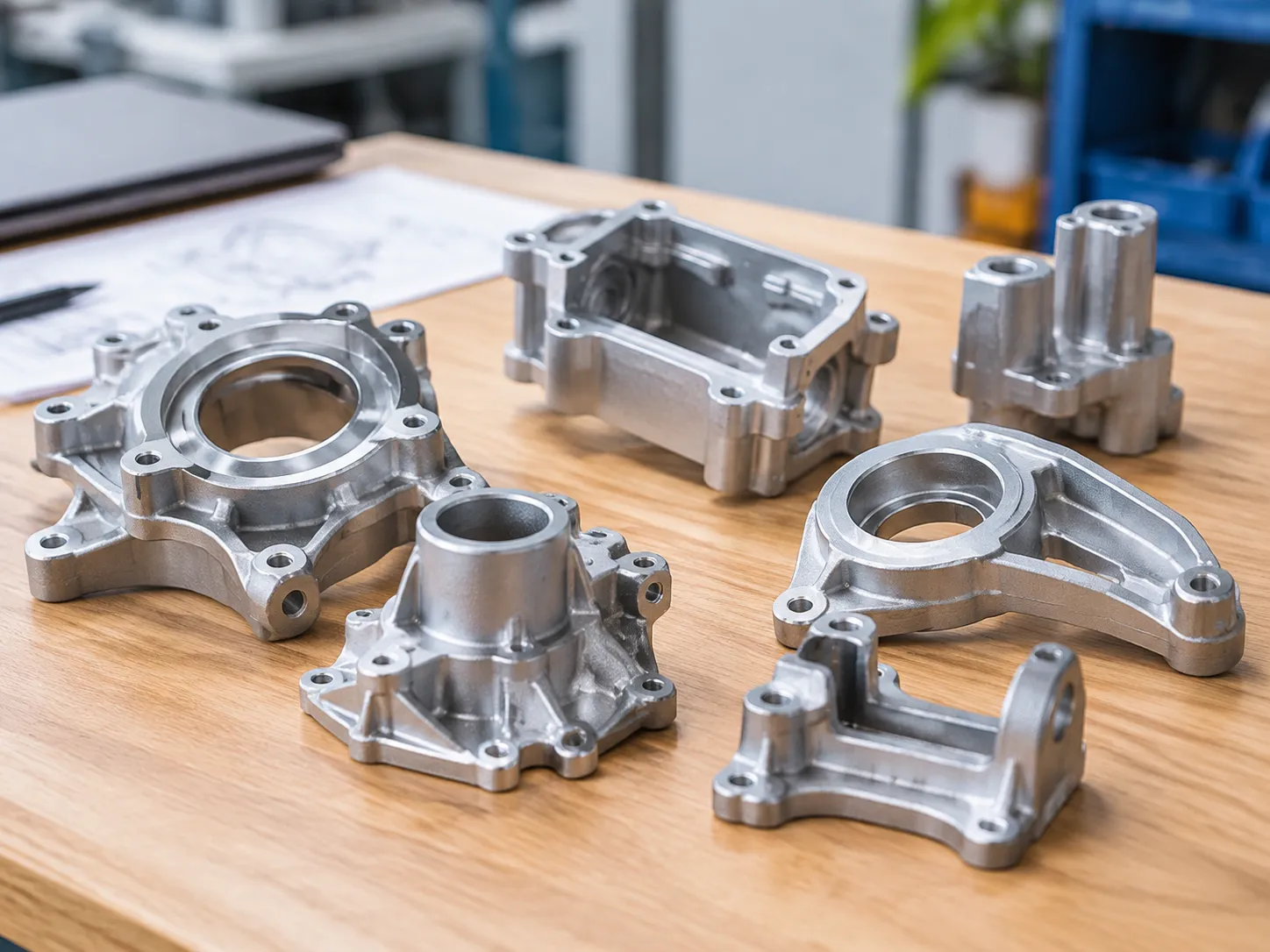
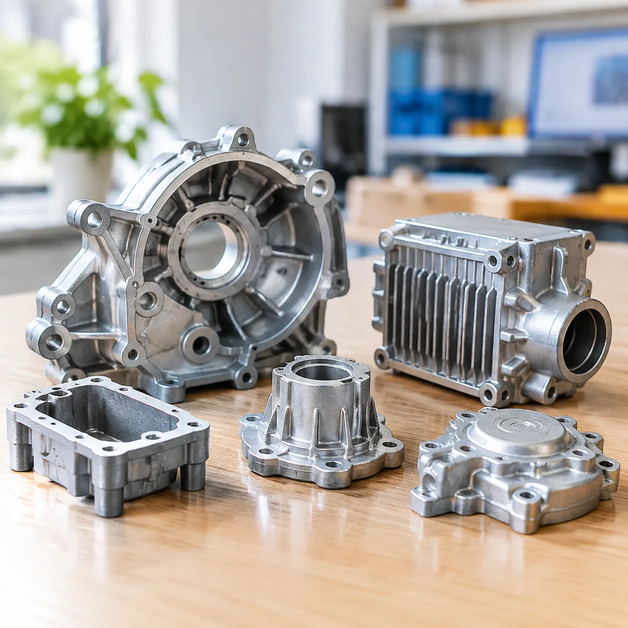
- High pressure die casting (HPDC). Liquid metal enters a steel cavity at 30-60 m/s gate velocity and solidifies in 20-200 ms. Cooling rate in a 2 mm wall is 200-800 K/s, giving a secondary dendrite arm spacing (SDAS) of 5-15 µm and a chilled, effectively pore-free skin 0.1-0.5 mm thick. The centre of a thick section cools far slower, SDAS opens to 25-50 µm, and that is where shrinkage porosity concentrates.
- Low pressure and gravity casting. Cooling rates of 1-20 K/s. SDAS 25-80 µm. Coarser, but the metal arrives at 0.05-0.5 m/s, so there is far less air entrainment and the parts respond to T6.
- Wrought. A DC-cast billet is homogenised at 500-580°C for 4-12 h, then hot rolled or extruded with 90-99% reduction. The cast dendritic structure is broken up, intermetallics are fragmented and aligned into stringers, and the grain structure recrystallises to 20-200 µm depending on product form and heat treatment.
The practical consequence is that a casting is a solidification structure with a property gradient from skin to core, while a wrought product is a deformation structure with a property gradient from longitudinal to short-transverse. Both are anisotropic; they are anisotropic in different axes.
Silicon is the other structural divider. Casting alloys carry 7-12% Si to buy fluidity and feedability; wrought alloys are capped near 0.4-1.0% Si (except 4xxx filler and 4032-type piston alloys) because coarse Si particles destroy ductility and wreck tool life. That one element explains most of the machining, anodizing and weldability behaviour below.
Mechanical property envelope
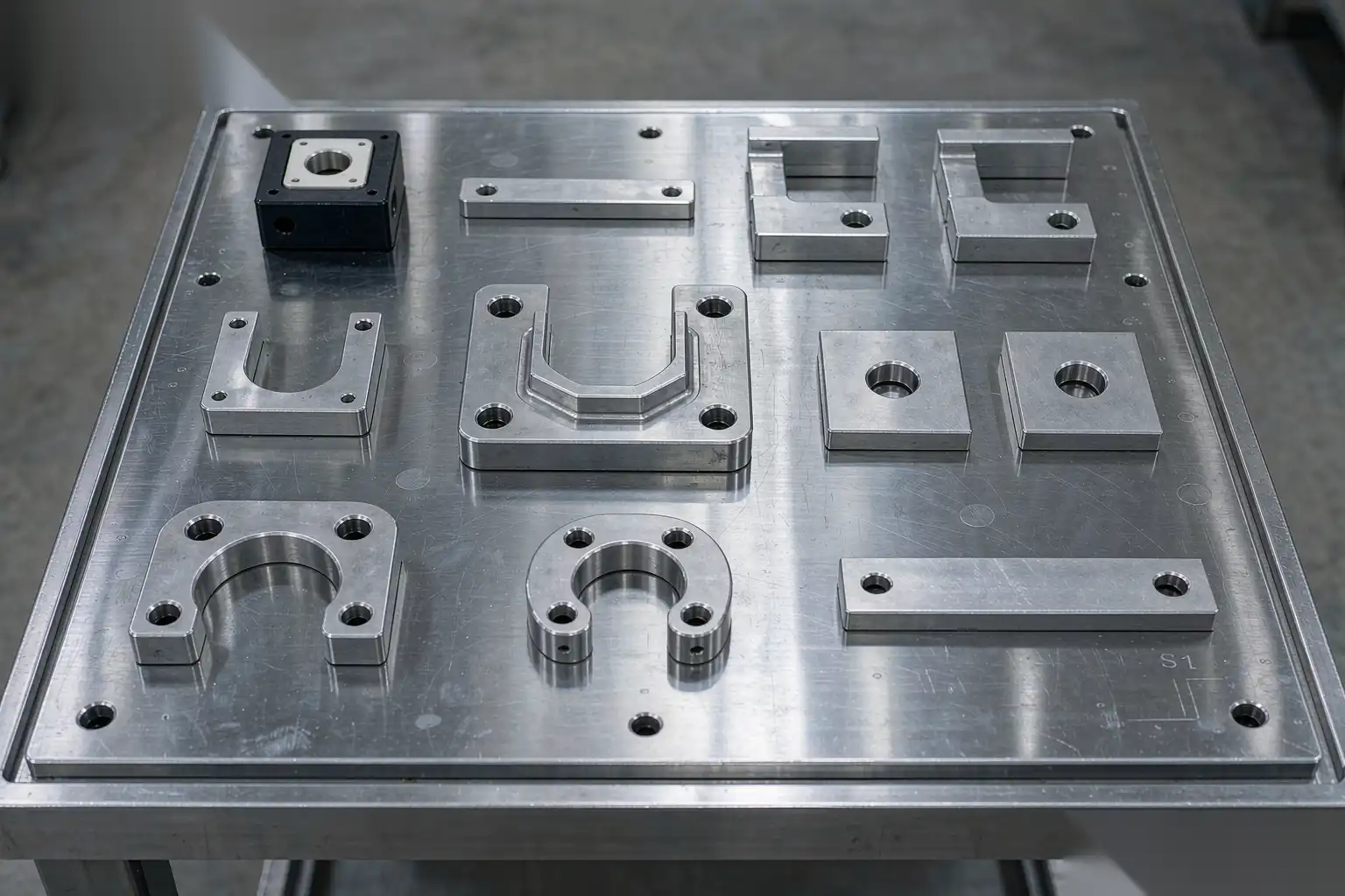
Numbers below are typical room-temperature values for separately cast or standard mill product test bars. Datasheet minima per ASTM B85, B26, B211 and B221 sit lower; design to the standard, not to the typical column.
| Alloy and temper | Route | UTS, MPa | Yield, MPa | Elongation, % | Hardness HB | Fatigue limit, MPa (5e8) |
|---|---|---|---|---|---|---|
| A380 / ADC12, as-cast F | HPDC | 310-330 | 150-170 | 2.5-4.0 | 80-90 | 90-110 |
| AlSi9Cu3(Fe), as-cast F | HPDC | 300-340 | 150-180 | 1.5-3.0 | 85-100 | 85-105 |
| A356.0-T6 | LP / gravity | 260-310 | 185-240 | 7-12 | 80-95 | 95-115 |
| A356.0, as-cast F | LP / gravity | 170-210 | 90-120 | 5-8 | 55-70 | 70-85 |
| 6063-T5 | Extrusion | 185-215 | 145-170 | 8-12 | 60-75 | 70-90 |
| 6061-T6 | Rolled / extruded | 290-330 | 255-290 | 10-16 | 90-100 | 95-110 |
| 5052-H32 | Sheet | 215-265 | 160-195 | 12-18 | 60-75 | 105-125 |
| 7075-T6 | Rolled / extruded | 540-580 | 470-510 | 8-11 | 150-160 | 150-170 |
Read that table with three corrections in mind. First, cast elongation is thickness-dependent: a 6 mm section of A380 can lose 30-40% of the elongation measured in a 3 mm section, because SDAS coarsens and microporosity triples. Second, cast fatigue numbers scatter widely and are dominated by the largest pore in the highly stressed volume, not by the mean; a design that is pore-sensitive should use a knockdown of 0.5-0.6 on the sand-cast or LP figure. Third, 7075-T6 buys its strength with corrosion and weldability, and is not a general-purpose answer.
If the load case is stiffness-driven rather than strength-driven, both routes land in the same place: Young’s modulus is 69-72 GPa for essentially every aluminum alloy, cast or wrought, and heat treatment does not move it. Stiffness is geometry, and geometry is where die casting wins, because ribs, bosses, variable walls and undercuts cost nothing once the tool exists.
Anisotropy: the datasheet number is a direction
Wrought anisotropy is standardised and predictable. For 7075-T6 plate, longitudinal elongation of 11% drops to 3-4% in the short-transverse direction, and short-transverse fracture toughness can be half the L-T value. If your part loads through the thickness of a rolled plate, the datasheet number is not available to you. The mitigation is either a forged or hand-forged form, or a design that keeps principal stress in-plane.
Cast anisotropy is different and less documented. Bulk properties are close to isotropic where the grain structure is fine and equiaxed, but there is a systematic gradient:
- Wall thickness effect. Thin-wall HPDC (1.5-2.5 mm) has SDAS of 5-10 µm and can show 15-25% higher UTS than a 6-8 mm section in the same shot.
- Skin effect. The 0.1-0.5 mm chilled skin is fine-grained, dense and often 10-20% harder than the core. Machining 1 mm off all faces removes the strongest material in the part.
- Flow-direction effect. Elongated intermetallic and oxide films from the fill front align with flow, so elongation measured across a flow front can be 30-50% lower than along it.
For a cast part, the honest way to get design allowables is to cut test bars from three locations in a real production casting — thin wall, thick boss, and across the last-fill area — and run at least 30 coupons per location to get a B-basis value. Our aluminum die casting tolerances guide explains how dimensional capability interacts with these gradients when you set machining stock.
Porosity, homogeneity and pressure tightness
This is where the two routes separate most sharply and where most field failures originate.
- Gas porosity. Hydrogen solubility drops from roughly 0.65 ml/100 g in liquid at 720°C to 0.05 ml/100 g in solid. Degas to below 0.15 ml/100 g (Telegas or equivalent) and you avoid most of it. HPDC adds a second source: air entrained by turbulent fill, mechanically mixed into the metal as 10-200 µm bubbles. Well-run HPDC holds total porosity at 1-3 vol% locally and below 1 vol% in stressed areas.
- Shrinkage porosity. Al-Si alloys shrink 3.5-6.5% depending on Si content; anything above about 12.6% Si is eutectic and feeds well, hypoeutectic alloys need risers or pressure. In HPDC the intensification pressure (60-100 MPa) does the feeding, but only while the gate is liquid; a 12 mm boss with a 2 mm gate freezes off and shrinks internally.
- Wrought. A rolled or extruded product is essentially fully dense. Ultrasonic inspection per AMS 2631 class B is routine. There is no mechanism that puts porosity into sound mill product.
Pressure tightness acceptance should be written as a number, not as “leak free”. Our shop practice for a hydraulic or pneumatic body:
| Test | Parameter | Acceptance |
|---|---|---|
| Air-under-water | 4-6 bar dry air, 30-60 s immersion | Zero continuous bubble stream; isolated bubbles at <1 per 30 s accepted only on non-critical castings |
| Pressure decay | Charge to 1.5x working pressure, 10-30 s stabilise, 30 s measure | Decay <1-2% of charge pressure, or <0.5 mbar on a 2 bar test |
| Helium sniff / vacuum chamber | Helium 10-30% tracer, mass spec | Leak rate below 1e-5 mbar·l/s for refrigerant-class parts |
| XCT sampling | Voxel 50-100 µm on one part per cavity per shift | No pore >0.5 mm within 1.5 mm of a sealing surface; <3% area porosity on any critical section |
Impregnation works, but treat it as a controlled process step, not a rescue. Vacuum-pressure resin impregnation with a low-viscosity methacrylate fills pores up to about 0.25 mm and recovers 85-95% of leaking parts. It does not restore fatigue life, it adds 40-90 minutes of cycle time and a wash step, and it puts a temperature ceiling of roughly 200°C on the part afterwards. If a program needs more than 2-3% impregnation, the casting process is not in control and the money should go into filling and venting instead.
Machinability, welding and surface response
Machining differs mainly because of silicon. Primary silicon and eutectic Si particles are 600-900 HV against an aluminum matrix of 60-100 HV; they abrade the cutting edge continuously.
- A380 / ADC12. Cutting speeds of 200-400 m/min with carbide and 400-900 m/min with PCD. Expect 3,000-8,000 holes per PCD drill in a 10% Si alloy versus 30,000-60,000 in 6061. Use sharp, polished, high-positive rake geometry, and avoid built-up edge by not dwelling.
- A356-T6. Lower Si and Sr-modified eutectic; noticeably less abrasive, better surface finish, but gummier at low speed. Roughly 20-40% better tool life than A380 in drilling.
- 6061-T6. Good chip breaking, long tool life, Ra 0.8-1.6 µm achievable dry.
- 5052 and 5xxx. Gummy, built-up edge below 150 m/min, needs sharp polished flutes and generous chip evacuation.
Weldability is nearly binary. A380 and ADC12 should be treated as non-weldable: the Cu plus high Si gives a wide freezing range, hot cracking, and the entrained gas expands into the weld pool. A356 is weldable with 4043 filler, and LP or gravity A356 is routinely repair-welded and re-heat-treated. 6061 welds with 5356 or 4043 but loses 40-50% of its strength in the heat affected zone unless the assembly is re-solution-treated and aged, which usually distorts it. 5xxx alloys weld well and retain most of their strength.
Surface response is the other hard divider, and it is what buyers notice first:
- Anodizing. 6063 and 6061 give a clean, uniform, bright anodic film. High-Si, high-Cu castings go grey to dark grey, blotchy, and the film is thinner and softer; the usual outcome is a dark decorative anodize or paint instead.
- Polishing and plating. Low-Si, low-Fe alloys such as A356 or a low-copper Al-Mg cast alloy reach a mirror finish with a three-stage buff; A380 and ADC12 will polish but the Si particles smear and the surface greys under chrome.
- Painting and powder coat. Both are fine on either route; castings need a sealed or outgassed cycle because entrained gas in shallow pores expands at 180-200°C cure and pinholes the film. Pre-bake at 200-220°C for 30-60 min, or powder on a properly converted and sealed surface.
If the part is decorative, the alloy choice and the route choice are the same decision. That is why our aluminum die casting finishing options article starts from alloy and as-cast surface state rather than from coating chemistry.
Cost structure and the volume break-even
The economics have four terms: tooling, converted material, cycle-driven machine and labour cost, and secondary operations.
| Cost term | Die casting | Wrought (extrusion or plate plus CNC) |
|---|---|---|
| Tooling | 15,000-120,000 USD, 8-16 weeks | 800-5,000 USD for an extrusion die, 4-6 weeks; none for plate |
| Material utilisation | 85-95%, runners and biscuits recycled in-house | 35-60% buy-to-fly, chips recover at 50-70% of ingot value |
| Piece cycle | 30-90 s per shot, 2-4 cavities typical | 3-15 min CNC from billet or sawed blank |
| Machining content | 1-3 setups, 20-90 s total | 1-4 setups, 2-12 min total, chip handling and coolant |
| Secondary finishing | Trim, blast, deburr, polish or coat | Deburr, blast, anodize or coat |
| Economic run length | 10,000 to 500,000+ per year | 5 to 5,000 per year |
The break-even is where fixed tooling amortised over quantity plus the low-variable casting route crosses the high-variable machining route. A usable form:
“`
N* = (Tool_HPDC – Tool_wrought) / (C_wrought_part – C_cast_part)
“`
Worked example. A 0.6 kg housing with 12 machined features. Tooling 48,000 USD for a two-cavity die against 3,000 USD for an extrusion die; delta 45,000 USD. Machined from extrusion the part costs 21.00 USD; as a casting with trim, blast and two CNC ops it costs 9.40 USD; delta 11.60 USD. Break-even is 3,880 pieces total, and at 12,000 pieces per year that arrives in the fourth month. Below roughly 1,000 pieces per year, the same housing should be machined from bar or plate and the 45,000 USD stays in the bank.
Two corrections make the model honest. First, add the carrying cost of tooling risk: if the design is immature, a die is expensive to change and an extrusion die or a CNC program is not. Second, add the cost of late engineering changes — a wall move in a die is 8-20% of tool cost and 4-8 weeks; on a billet it is a program edit.
Decision matrix
| Requirement | Best route | Why |
|---|---|---|
| Thin walls under 2 mm over a large area | HPDC | Only route with the velocity and pressure to fill it |
| Complex 3D shape, ribs, bosses, undercuts | HPDC | Geometry is free once the tool is cut |
| Pressure tightness above 10 bar, as-cast | LP or gravity then machine, or wrought | Gas porosity in HPDC makes this a gamble |
| T6 heat treatment required | LP, gravity or squeeze | HPDC blisters above ~480°C solution |
| Welded or repair-welded assembly | Wrought 5xxx/6xxx, or A356 | Cu-bearing HPDC alloys crack |
| Elongation above 10% on a production part | Wrought, or A356-T6 | Cast elongation is thickness-limited |
| Mirror polish and decorative chrome or PVD | Low-Si cast alloy or wrought 6063 | Si and Fe grey the finish |
| Structural aircraft or motorsport load case | Wrought 7075 or 7050, forged | B-basis allowables and damage tolerance |
| Annual volume below ~1,000 | Wrought plus CNC | Tooling cannot be amortised |
| Lead time under 6 weeks to first parts | Wrought plus CNC | Tool build dominates the schedule |
| Part count consolidation of 6-10 pieces into 1 | HPDC | Net-shape saves assembly, fasteners and leak paths |
Where wrought is genuinely the right answer
Say this plainly in the design review, because forcing a casting into these cases is expensive:
- Fatigue-critical, damage-tolerant structure with an inspection regime. Wrought product has certified allowables and fracture toughness data; castings require you to generate your own.
- Highly loaded thin plate or sheet-metal-like geometry, where a 1.5 mm wall in HPDC is possible but a 1.5 mm formed sheet is cheaper and stronger in bending.
- Very low volume or one-off, including prototypes. A machined prototype from 6061 tells you about the design, not the casting process; but it is the right first article when volume is unknown.
- Welded fabrications — frames, tanks, enclosures made from 15 parts. A casting would be better only if volume justifies the tool.
- Anodized architectural or consumer surfaces where the finish is the product.
- Cryogenic or elevated temperature service above about 200°C, where cast microstructure coarsens and the property drop is larger than for wrought.
How as-cast condition drives the finishing cell
The route you choose determines the work content downstream, and that is where most of the delivered cost actually sits. A die casting arrives with a parting line witness of 0.05-0.30 mm, flash at slides and ejector pins, a gate scar of 2-15 mm², and a surface that varies from Ra 1.6 µm on a good as-cast face to Ra 6-12 µm where die lubricant burned on. A wrought blank arrives with saw marks, burrs at every milled edge, and a consistent Ra 1.6-3.2 µm.
For cast parts the finishing sequence is fixed by that input condition: trim at 20-200 t depending on shear perimeter, band-saw the LP riser or the HPDC gate, vibratory or shot-blast to a uniform Ra, then grind the parting line in a progression (60-80 grit for gate removal, 120-180 to blend, 240-320 to pre-polish), then cut and colour buff if the part is decorative. Because the input varies from shot to shot, the only stable way to automate it is compliant force control: a floating spindle holding 5-40 N against the part with a media-wear compensation routine, rather than a fixed path that either digs in on a fat casting or misses on a thin one. That is the architecture DZ Machinery builds into its robotic deburring and grinding cells, and it is the same reason our automatic deburring machine range is specified by as-cast variation and not by part number.
DZ Machinery builds robotic deburring, grinding and polishing cells and complete turnkey lines for cast and wrought parts, with the fixture, dust extraction and cycle-time study included; if you are running a die-cast-versus-wrought decision on a live program, send the part drawings and the annual volume and our engineering team will model both routes and the finishing cell that each one needs.