Low Pressure Aluminum Die Casting: Process Mechanics, Porosity Limits and the Real Trade-Off Against HPDC
Low pressure die casting (LPDC) is the route that sits between gravity permanent mould and high pressure die casting, and it is chronically mis-specified because buyers compare it to HPDC on cycle time alone. The cycle is slower. The reason to choose it is that the metal arrives in the cavity at a velocity two to three orders of magnitude lower, which changes the porosity population, which in turn unlocks heat treatment, welding and pressure tightness. If your part needs any of those three, LP is not a slower HPDC, it is the only route available in a permanent mould.
This guide covers the mechanics of the cycle, the filling numbers that matter, wall thickness and cycle time capability, the porosity levels that are actually achievable and why they permit T6, the part families that use the process, a cost-per-kilogram comparison, and an honest statement of when HPDC still wins.
How the low pressure cycle works
The machine is a sealed holding furnace below the die, a riser tube (stalk) dipping into the melt, and a die above it. A controlled gas pressure of 0.02-0.10 MPa (0.2-1.0 bar) is applied to the furnace bath surface and pushes metal up the stalk and into the cavity from the bottom.
| Phase | Typical parameter | What it controls |
|---|---|---|
| Stalk fill / rise | 0.02-0.05 MPa, 5-20 s | Oxide film formation in the riser; too fast drags dross into the cavity |
| Cavity fill | 0.04-0.10 MPa, 20-80 s | Front velocity, misrun and cold shut risk |
| Pressurisation | 0.08-0.15 MPa ramp | Feeding during solidification |
| Hold under pressure | 0.05-0.10 MPa, 30-180 s | Shrinkage feeding while the section solidifies |
| Release and solidify | Pressure vent, residual metal returns to the furnace | Yield: un-solidified stalk metal drains back, typically 85-95% metal utilisation |
| Open, eject, core set | 15-60 s | Cycle time and die thermal balance |
Four process features follow from that layout and they are the reason the microstructure is what it is:
- Bottom-up filling. The cavity fills from the lowest point with the free surface rising, so displaced air exits through vents and parting line gaps ahead of the metal. There is no atomised spray of droplets.
- The stalk is the gate. Residual metal in the stalk returns to the furnace, so the returns loop is closed and clean, unlike HPDC where the biscuit and runner go through a remelt and dross loss cycle.
- Pressure is applied through solidification. Feeding pressure of 0.05-0.15 MPa is maintained until the part is fully solid, so shrinkage cavities at hot spots are fed rather than formed.
- Sand cores are possible. Because filling is slow and pressure is modest, complex internal passages can be cored with bonded sand and then knocked out, which is how closed-deck water jackets and hollow faucet bodies are made. HPDC cannot hold a sand core against 60 MPa of intensification.
Filling velocity and turbulence: the numbers that matter
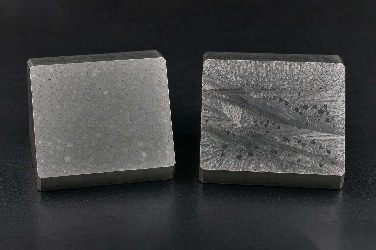
Air entrainment is the mechanism that separates the two processes. A rough but useful criterion for aluminium is a critical free-surface velocity of 0.5-1.0 m/s; above it the surface breaks up and folds oxide and air into the liquid.
| Parameter | HPDC | LPDC | Gravity permanent mould |
|---|---|---|---|
| Gate / ingate velocity, m/s | 30-60 | 0.3-1.5 | 0.3-1.0 |
| Cavity front velocity, m/s | 5-50 | 0.02-0.10 | 0.05-0.30 |
| Cavity fill time, s | 0.02-0.20 | 20-80 | 5-40 |
| Metal pressure during solidification, MPa | 60-100 | 0.05-0.15 | 0.005-0.02 |
| Turbulence regime | Atomised, dispersed flow | Laminar, quiescent front | Laminar to wavy |
| Bifilm / oxide entrainment | High | Low | Low to moderate |
| Dissolved hydrogen limit, ml/100 g | <0.15 and still gas porous | <0.15 | <0.15 |
Two consequences that show up on the inspection bench. First, the laminar front in LP means oxide bifilms stay at the surface or are caught in a riser, so the oxide population inside the casting is small; in HPDC it is distributed through the section. Second, LP has no shot-sleeve pre-fill wave, so there is none of the air that gets swept in by the plunger at slow-shot and then compressed to 50-70 MPa at intensification.
The cost of that gentleness is fill time. At 0.05 m/s a 400 mm tall wheel needs 8 s just to move the front the full height, and the real fill is 20-40 s. Thin sections freeze before the front arrives, which is exactly why LP has a wall thickness floor.
Wall thickness, cycle time and section capability
| Capability | HPDC | LPDC |
|---|---|---|
| Minimum practical wall | 0.8-1.5 mm over short flow lengths | 3.0-4.0 mm typical, 2.5 mm feasible on small parts |
| Nominal wall | 2.0-4.0 mm | 4-8 mm |
| Maximum useful section | 6-10 mm before shrinkage dominates | 25-40 mm, and thick sections are the point |
| Section ratio within one part | Keep within 2:1 | 4:1 is manageable with risers and chills |
| Casting weight range | 0.02-20 kg | 0.5-60 kg |
| Dry cycle time | 30-90 s | 90-480 s |
| Yield (good parts / metal poured) | 55-80% | 85-95% |
Cycle time is dominated by solidification, not by the machine. Solidification time for a plate is approximately proportional to the square of the section thickness, so an 8 mm wall takes roughly four times as long as a 4 mm wall. A 17-19 inch wheel runs 240-330 s per cavity on a four-cavity machine, giving roughly 60-90 s per part. A two-cavity faucet body tool with 5 mm nominal wall runs 90-140 s per shot, about 50-70 s per part. Compare that with 40-70 s for a comparable-size HPDC shot, and the gap is real, but note that LP tools are routinely multi-cavity (2, 4 or 6) precisely to dilute it.
Die thermal balance matters more in LP because the stalk is a permanent heat sink and a permanent heat source at the same time. Stalk tip temperature is held at 650-700°C, and a cold stalk on the first shots of a shift is a classic source of misruns and cold shuts. Running a 15-30 minute warm-up and scrapping or 100% inspecting the first three to five shots per shift start is standard practice.
Porosity levels and why LP parts can be heat treated
This is the decisive technical difference. Give it numbers:
| Measure | HPDC, good practice | LPDC, good practice |
|---|---|---|
| Total porosity, vol% | 1.0-3.0 | 0.1-0.5 |
| Largest pore in a stressed section | 0.3-1.5 mm | 0.05-0.30 mm |
| Blistering on solution treatment | Severe above 480°C | None |
| Blistering or distortion in paint bake at 200°C | Occasional pinholing | Rare |
| Helium leak rate on a machined body | 1e-3 to 1e-5 mbar·l/s, impregnation often needed | Routinely below 1e-6 mbar·l/s |
| Typical X-ray class (ASTM E155, 6 mm) | 3-5 | 1-2 |
The blistering mechanism is simple enough to explain to a customer. A gas pore at 100 µm contains air at roughly the intensification pressure during solidification. Heat the part to a 535-545°C solution temperature and three things happen at once: the yield strength of the matrix falls to under 40 MPa, the entrapped gas expands by a factor of roughly two in absolute temperature, and hydrogen that was rejected into the pore during solidification goes back into solution and adds pressure. The pore becomes a pressurised void in a soft matrix and it grows. On an as-cast surface that reads as a blister 0.5-3 mm across. Under a machined skin it reads as a bulge and a dimensional reject.
Because LP porosity is an order of magnitude lower and the pores are an order of magnitude smaller, LP parts can be solution treated, quenched and aged like any other casting, and the mechanical gain is substantial.
| Alloy and condition | UTS, MPa | Yield, MPa | Elongation, % | Hardness HB |
|---|---|---|---|---|
| A356.0, as-cast F | 170-210 | 90-120 | 5-8 | 55-70 |
| A356.0-T6 | 260-310 | 185-240 | 7-12 | 80-95 |
| A356.0-T61 (quench delay control) | 240-280 | 165-205 | 6-10 | 75-90 |
| A357.0-T6 | 300-345 | 240-290 | 6-10 | 90-105 |
| AlSi7Mg0.3 + 0.2% TiB grain refiner, T6 | 290-330 | 220-260 | 8-13 | 85-100 |
A full T6 route for A356 is solution at 535-545°C for 4-8 h depending on section, water quench at 60-80°C with less than 10-15 s transfer time, natural age 2-8 h, then artificial age at 150-170°C for 4-8 h. Quench delay is the variable that quietly destroys properties: every minute of delay above about 400°C costs yield strength, and the fix is a quench robot or a drop-bottom furnace, not a change to the ageing cycle.
Note also that heat treatment adds cost and distortion. Budget 0.35-0.90 USD/kg for the heat treatment itself depending on energy cost and load density, add straightening or a fixture-age route for thin-rim parts, and add 8-24 h of queue time through the furnace. Our aluminum die casting defects and solutions reference lists which defects are casting-process defects and which are heat-treat defects, since the two are often confused.
Typical parts, and the numbers behind them
LP owns the parts where a thick section, a pressure boundary, or a weld repair matters:
- Road wheels, 15-24 inch. A356-T6, 8-12 kg, rim 4-6 mm and spoke-to-hub junctions to 30 mm. One casting per cavity, four-cavity machines common. Acceptance: X-ray per ASTM E155 at the hub and rim, radial fatigue to 1e6-1e7 cycles at 1.5-2.5x rated load, impact test, and a helium or air-under-water leak test on every wheel. This is the highest-volume LP application in the world.
- Faucet and sanitary bodies. Single- and two-handle mixer bodies in low-copper Al-Si or brass-adjacent aluminium alloys, 0.4-1.8 kg, 3-6 mm wall, sand-cored waterways. The requirement is not strength, it is a defect-free surface at the chrome or PVD layer, plus a 6-10 bar pressure test. Every one of these parts goes through gate sawing, parting-line grinding and multi-stage polishing, which is exactly the flow DZ Machinery automates for sanitary plants.
- Cylinder heads and engine blocks (aluminium). Sand-cored water jacket and ports, 8-25 kg, T6 or T7, pressure tested at 2-5 bar on the water jacket. Rotated or tilted LP machines improve feeding.
- Suspension and structural nodes. Control arms, knuckles, subframe nodes in A356-T6 or A357-T6, 2-8 kg, elongation requirement of 7-10% minimum at the production casting, and often a proof-load or burst test on a sampling plan.
- Pressure vessels and pump bodies. Water meter housings, valve bodies, compressor shells, where a 10-25 bar proof test is required and impregnation is not acceptable.
- Heat sinks with thick bases and tall fins. LP fills fine, thermally conductive, and the base section is precisely where HPDC would shrink.
Cost per kilogram and where the money goes
Indicative converted cost of a finished casting, metal included, at 2026 ingot levels and a 100,000-piece-per-year programme. Treat these as relative, not absolute; labour rate and energy cost move them by ±30%.
| Cost element | HPDC, USD/kg | LPDC, USD/kg |
|---|---|---|
| Metal (ingot plus melt loss) | 2.00-2.60 | 2.00-2.60 |
| Melting, holding and degassing energy | 0.10-0.25 | 0.15-0.35 |
| Machine and labour per kg | 0.35-0.80 | 0.60-1.40 |
| Tooling amortised over programme | 0.08-0.40 | 0.10-0.45 |
| Cores (only where used) | 0.00-0.15 | 0.20-0.80 |
| Heat treatment | 0.00-0.10 | 0.35-0.90 |
| Trim, saw and fettling | 0.15-0.45 | 0.20-0.50 |
| Inspection and leak test | 0.05-0.30 | 0.10-0.40 |
| Indicative total | 2.80-5.00 | 3.80-7.50 |
LP is typically 20-50% more expensive per kilogram. The offset is that LP parts are often heavier in the first place because of the wall thickness floor, so compare at part level, not at kilogram level: a 1.6 kg LP wheel hub against a 1.1 kg HPDC housing is not a 45% cost penalty, it is a different part.
Tooling is closer than most people assume. An LP tool has no shot sleeve, no biscuit and lower clamping loads, so the die steel and the holder can be lighter, and a 30-80 t clamp does the work of a 400-800 t HPDC machine. Machine capital for a four-cavity LP wheel cell is a fraction of an equivalent-output HPDC cell, which is why the annual volume at which LP becomes cheaper than HPDC-plus-impregnation is lower than the cycle-time comparison suggests.
Decision table: LP wins, HPDC wins
| Condition | Winner | Reason |
|---|---|---|
| Wall below 2.5 mm over long flow | HPDC | LP will misrun |
| Wall above 6 mm, or hot spots above 12 mm | LP | HPDC shrinks; LP feeds under pressure |
| T6 or T5 required | LP | HPDC blisters |
| Weld repair or welded assembly | LP | Low gas content |
| Pressure tightness above 10 bar without impregnation | LP | Porosity population |
| Sand-cored internal passages | LP | Core survives the pressure |
| Annual volume above 300,000 small parts | HPDC | Cycle time dominates |
| Cosmetic as-cast surface on large flat area | HPDC | Surface replication is better |
| Part weight below 0.3 kg | HPDC | LP cycle penalty is not recoverable |
| Dimensional tolerance tighter than CT6 | HPDC, with machining | LP is CT7-CT8 as-cast; machine either way |
| Programme life under 20,000 total | Depends on tooling | Both are tooling-heavy; consider gravity or machined billet |
Where HPDC remains the correct answer is thin-wall, high-volume, non-structural, non-heat-treated parts: electronic housings, brackets, small motor shells, transmission cases with machined sealing faces, and any part where the as-cast surface is the cosmetic surface. Where LP is correct is anything thick, pressure-tight, heat-treated or welded. Where neither is correct is a 300-piece-per-year prototype: that belongs in a machined billet or a sand casting until the design settles.
What the LP casting hands to the finishing line
As-cast condition differs enough between the two routes that the downstream cell has to be designed for it. An LP part typically arrives with one or two large gates or a riser stalk scar of 15-60 mm diameter at a location chosen for feeding, usually on the hub or the non-cosmetic face; a parting line witness of 0.1-0.4 mm; and a surface at Ra 6.3-25 µm where the die coating has roughened over a long cycle. There is no biscuit and usually no overflow network, so there is less flash, but the gate cross-section is far larger and needs a saw rather than a trim die.
That changes the routing: band saw with a 2-3 mm kerf and a dedicated fixture that supports the part against the feeding boss, then a coarse grind at 36-60 grit to bring the gate scar flush, then 120-180 and 240-320 to blend, then cut and colour buff for chrome or PVD. Because the gate is a large, repeatable feature rather than a thin witness line, this is the easiest of all deburring jobs to robotise, and the payback is correspondingly fast: a manual gate-grind station runs 60-120 s per part with an operator and a dust problem, a robotic cell with a compliant spindle and a two-station rotary table runs 30-50 s per part with one operator tending two cells.
DZ Machinery builds robotic deburring, grinding and polishing cells and complete turnkey sanitary lines covering core shooting, low pressure or gravity casting, band sawing, CNC, robotic grinding and automatic polishing, and we size each station from the actual as-cast condition rather than from the drawing. If you are deciding between LP and HPDC on a live part, send us the model, the alloy, the annual volume and the acceptance tests, and our engineering team will model both routes and the finishing line each one requires.