Aluminum Die Casting for Consumer Electronics Enclosures
Consumer electronics enclosures are a demanding application for aluminum die casting because the part is both a structural and an aesthetic object. It must shield electromagnetic interference, stay rigid under drop and torsion, spread heat from internal components, and still look like a premium consumer product on a shelf next to extruded and CNC-machined rivals. High-pressure die casting meets those demands at a volume and unit cost that machining cannot, provided the wall thickness, surface, and tolerances are designed for the process. This article covers how we at DZ Smart Manufacturing approach aluminum enclosures for electronics, from material choice to automated finishing.
Why die casting for device housings
The first question a product team asks is why cast at all when CNC machining an enclosure from billet gives perfect surfaces. The answer is volume and function integrated into one part.
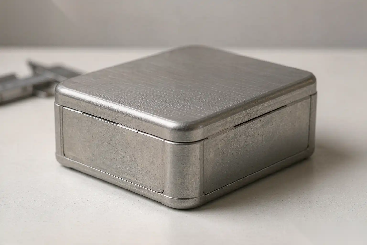
EMI shielding is built into the metal. An aluminum housing is a continuous conductive shell that attenuates radiated interference without extra gaskets on every face. For Wi-Fi, Bluetooth, and cellular bands, a die-cast aluminum enclosure commonly provides 30 to 60 dB of shielding depending on seam design and plating, which is hard to match with plastic plus a sprayed coating.
Rigidity comes from the casting shape. Ribs, bosses, and integral standoffs are free in the die, so the enclosure resists bend and twist better per gram than a thin stamped shell. For a tablet or a router base, this means fewer internal brackets and a quieter, more solid product.
Heat spreading is a property of aluminum itself. With thermal conductivity near 90 to 120 W per meter-kelvin for the common die-cast alloys, the housing acts as a heat sink for processors and power stages, often removing the need for a separate stamped heat spreader.
Cost at volume is the clincher. A machined enclosure wastes most of the billet as chips and needs long cycle times per part; a die-cast part is near net shape in 30 to 70 seconds and needs only trimming and light finishing. Above a few thousand pieces, the casting wins on unit cost by a wide margin, which is detailed in our aluminum die casting applications by industry guide.
Wall thickness and thin-wall design
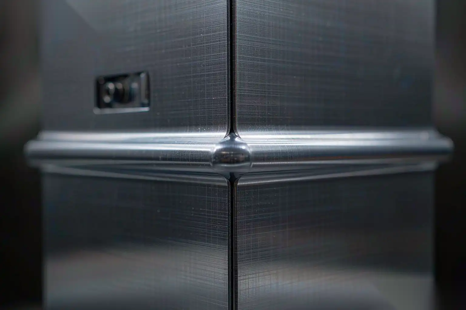
Electronics enclosures want thin, light walls, but die casting has a floor set by fill and strength. The thin-wall design limits are covered in our aluminum die casting thin wall design guide.
For aluminum HPDC we hold functional walls around 1.5 to 2.5 mm on smaller enclosures and 2.0 to 3.0 mm on larger ones. Going below 1.2 mm risks cold shut and incomplete fill at the far corners, especially with long, thin features. The fill velocity and gate design must be tuned so the metal reaches the last cavity before it freezes; this is where flow simulation earns its cost.
Uniform wall thickness is the rule that protects cosmetics and dimension. A sudden jump from 2 mm to 6 mm creates a sink on the visible face and a hot spot that warps the part. We keep section changes gradual and put extra material only where a boss or a standoff actually needs it, then core it out behind to save mass and cycle time.
Ribs and bosses are how we get stiffness without thick walls. A 1.0 to 1.5 mm rib on a 2 mm wall raises bending rigidity substantially for almost no extra mass, and a boss cored to leave a 1.5 to 2.0 mm wall gives a screw seat without a heavy block. The rib-to-wall ratio is kept near 0.6 to 0.8 of the wall so the rib does not sink.
The table below shows typical enclosure section targets.
| Feature | Target wall | Note |
|---|---|---|
| Main side wall | 1.5-2.5 mm | Thinner needs high fill velocity |
| Internal rib | 1.0-1.5 mm | Keep below wall to avoid sink |
| Screw boss wall | 1.5-2.0 mm | Core out the center |
| Corner radius | 0.5-1.0 mm | Eases fill, avoids stress |
| Seam flange | 2.0-3.0 mm | Stiffness at the joint |
Surface finish and the consumer look
The visible face of a consumer enclosure is judged like a phone or a speaker, not like an industrial part. Reaching that look from a casting needs control at three stages: the die surface, the cast skin, and the finish.
Die surface finish sets the floor. We polish the cavity face for visible areas to a roughness around Ra 0.4 to 0.8 micrometers so the as-cast skin is already smooth, reducing the finishing load. Ejector marks, parting-line flash, and gate vestiges on the visible face are designed away or moved to hidden edges.
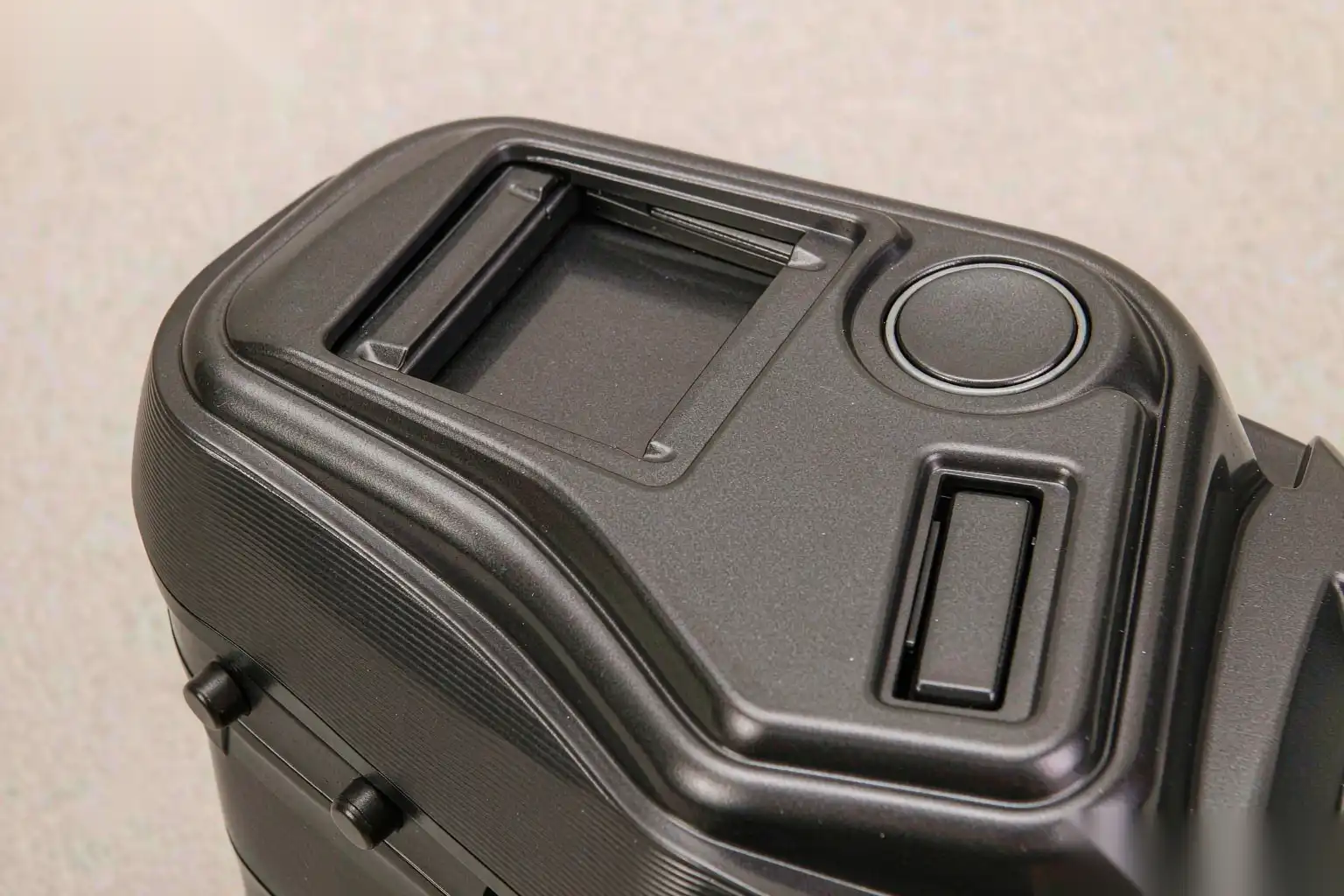
The as-cast skin is then treated to the consumer spec. For a raw aluminum look, a fine bead-blast gives a uniform matte; for a brighter look, a light polish followed by a clear coat. The choice depends on whether the brand wants a soft-touch matte or a techy satin.
Coating is where the premium feel is locked in. Anodizing and powder coat are the two routes, and the anodizing path for cast aluminum is specific enough that we keep a dedicated die cast aluminum anodizing guide. Die-cast skin has a fine porosity that can spot under anodize, so we often use a pre-treatment, a controlled etch, and sometimes a seal or a clear powder to cover it.
Color consistency across a run is a hard acceptance criterion. A batch of enclosures that drifts between two shades at the assembly line is a reject, so the finish parameters are fixed in the recipe and monitored, not tuned by eye between shifts.
Tolerances for snap-fits and sealing
Electronics enclosures assemble with snap-fits, press-fits, and gasketed seals, all of which need tolerances tighter than the die-cast default. Standard HPDC aluminum holds plus or minus 0.1 to 0.2 mm per 25 mm of dimension, which is often not enough for a snap-fit or a gasket groove.
Snap-fits need a controlled interference. We design the cantilever with a known deflection and a wall that will not crack, then hold the engage dimension by machining the snap ledge or by designing the die to hold it consistently. If the fit is critical, we machine the snap feature after casting; if it is forgiving, we trust the cast dimension with a verified process window.
Sealing grooves and gasket faces need flatness and position. A gasket that sees a 0.2 mm step at the parting line will leak, so we either move the parting line off the seal, machine the seal face, or design a compression gasket with enough take-up to absorb the variation. The decision is made at DFM, not after a leak test fails.
Holes and bosses for screws are usually cored slightly undersize and then tapped or reamed, because a cored thread in die cast aluminum is rarely good enough for a consumer assembly that is opened by the user. We core the hole straight and leave a machining allowance only where the feature truly needs it, to keep cost down.
The tolerance strategy is a trade between cast and machine. We cast the envelope and the visible surfaces to spec, and machine only the few features that the product function demands, which keeps cycle time and cost low while meeting the assembly.
Volume economics and when casting wins
The break-even between machining and casting is the question every program should answer before tooling. The variables are volume, part complexity, and finish.
Below roughly 1,000 pieces, CNC machining usually wins because there is no tooling amortization and design changes are free. Between 1,000 and 10,000 pieces, the decision flips as the die cost spreads and the per-part cycle advantage grows. Above 10,000 pieces, die casting is almost always cheaper per unit and the finish automation pays back fast.
Complexity pushes the break-even lower. A housing with ribs, standoffs, EMI fingers, and a sealed flange machines slowly and wastes material; cast, those features are free in the die, so casting wins sooner. A plain box with no features may stay cheaper machined longer.
Finish cost scales with the look. A raw blasted enclosure is cheap to finish; a mirror anodized one with tight color spec costs more, but the casting still beats machining on material and cycle. We model unit cost across volume bands before recommending a process so the program is not surprised at 5,000 pieces.
Scrap and yield are part of the economics. A casting line that ships 3 percent scrap is throwing away finished finish labor; we track yield by defect code and close the loop so the cost model stays honest across the run.
Tooling lead time is the other variable a program plan must hold. A new enclosure die with integrated EMI features and a polished cavity typically needs several weeks of design, steel, and tryout before first articles, so the casting decision has to be made early enough that the tool is ready when the product launch locks. We recommend freezing the enclosure geometry and the finish spec at least one development spin before the casting tool is cut, because a late change to a wall or a seam costs a die revision that machining would have absorbed with a new program.
Robotic deburring and polishing for a consistent consumer finish
Consumer volumes and consumer tolerances for appearance mean manual finishing does not hold up. A polisher’s output drifts with the shift, and labor cost in developed markets makes hand finishing uncompetitive. Automated finishing is how a cast enclosure keeps a uniform look across a 50,000-piece run.
A DZ robotic cell handles the enclosure sequence: deburr the parting line and gate with a compliant spindle and carbide or abrasive tool, then break edges with a radial brush for a safe, consistent radius, then polish the visible face to the spec roughness. For a matte consumer look the cell bead-blasts or brushes to a set Ra; for a bright look it runs cut and color compounds on wheels with metered feed.
Force control is what makes the finish repeatable. The robot holds a set normal force against the part through a compliant head, so an enclosure that is 0.2 mm proud in one area is finished the same as a nominal one. Wheel wear is tracked and the program compensates dress cycles, so batch 1 and batch 50,000 match.
Cycle time on a small enclosure commonly lands between 20 and 50 seconds for deburr plus polish, depending on finish class, which supports the cell throughput the casting line produces. The fixtures locate the part on stable datum and keep the visible face clear of clamps so no tool mark lands where the customer looks.
Integration with the casting line matters. We place the finishing cell right after trim and wash so the enclosure moves through as a clean, burr-free, uniformly finished part, and we monitor first-pass yield so a cosmetic drift is caught at the cell, not at final assembly.
Design checklist before tooling an enclosure
We close an electronics enclosure review with a short list so the program avoids re-tooling:
- Confirm the shielding need and design the seam and any EMI fingers into the cast shape.
- Set wall thickness in the 1.5 to 2.5 mm band and keep section changes gradual to avoid sink.
- Put ribs and bosses where stiffness and standoffs are needed, cored to save mass.
- Decide the consumer finish: matte blast, satin polish, anodize, or powder, and set the roughness target.
- Identify the few features that must be machined (snap ledges, seal faces, screw holes) and core the rest.
- Model unit cost across volume to confirm casting beats machining at the planned run.
- Plan automated deburr and polish with force control for a consistent look at volume.
Aluminum die casting gives consumer electronics a shielding, rigid, heat-spreading enclosure at a unit cost machining cannot match, as long as the walls, tolerances, and finish are designed for the process. DZ Machinery builds the robotic deburring, grinding, and polishing cells that turn raw aluminum enclosures into consistent consumer-grade finishes at production rate; if you are developing an electronics housing and want to review part drawings, wall design, and a finishing cell layout, our engineering team can run a feasibility and cycle-time estimate on your components.