Aluminium Melt Degassing and Filtration: Targets, Filter Choices, and Why Pitting Appears Only After Polishing
Melt quality is the one variable in die casting that nobody can see and everybody pays for. It does not show up at the casting machine, it does not show up at trim, and it usually does not show up at receiving inspection. It shows up at the polishing wheel, at the leak test after machining, and in the anodising tank.
We build robotic grinding and polishing cells, so we see the failure end of this. A cosmetic part that arrives at the cell looking perfect can come off it covered in pinholes, because polishing removes the skin that was hiding the pores. When that happens, the argument always runs toward the finishing cell, and almost always the root cause is three operations upstream in the melting department.
Covered below: where hydrogen actually enters the melt, realistic measurement targets and the limits of each test, rotary degassing parameter windows, the role and real cost of flux, filter options with pore sizes and capacities, inclusion types and how they become leak paths, holding furnace practice, a sampling plan that catches problems early, and finally acceptance criteria written in terms the finishing cell can actually work to.
Where Hydrogen Comes From
Hydrogen enters aluminium melt from any source of water or hydrocarbon that contacts metal above roughly 660 °C. The reaction is simple and unforgiving: aluminium plus water vapour gives alumina and atomic hydrogen, and the hydrogen goes into solution.
- Wet or damp charge. Returns stacked outdoors through a wet season, ingots stored without cover, and any scrap that has been rained on. This is the largest single source in most plants that do not control it. Returns from the casting cell are usually still warm and carry water-based die lubricant residue, which is a double contribution: the water itself, plus organic residue that cracks to hydrogen.
- Combustion atmosphere. In a gas fired furnace, burning methane produces roughly two molecules of water for every molecule of fuel. Furnace atmospheres routinely contain 10 to 20 percent water vapour. Any melt held under that atmosphere with a poor lid seal will pick up hydrogen continuously.
- Unpreheated tools. Skimmers, ladles, thermocouple sheaths, launders and ladle linings that have picked up condensate or have absorbed moisture. A cold steel skimmer dipped into 720 °C aluminium injects hydrogen at exactly the wrong place.
- Corroded and heavily oxidised scrap. Aluminium corrosion product is hydrated oxide, and it decomposes in the melt to give water directly.
- Wet or poorly stored flux. Hygroscopic chloride fluxes pull moisture out of the air in days if the drum is left open.
- Excessively high holding temperature and long holding time. Hydrogen solubility rises steeply with temperature, and an unnecessary 50 °C of superheat can undo a good degassing treatment within a couple of hours.
The physical reason this all matters is the solubility ratio. Liquid aluminium near 700 °C can hold on the order of 0.9 to 1.3 mL of hydrogen per 100 g depending on alloy and temperature; solid aluminium at room temperature holds around 0.04 mL per 100 g. That ratio is roughly 15 to 1 or more. Everything above the solid solubility has to go somewhere when the metal freezes, and where it goes is into pores.
Note the practical consequence for high pressure die casting specifically: the very fast solidification of HPDC means gas pores stay small, often tens of micrometres, and the process tolerates hydrogen better than gravity or low pressure casting does. That tolerance disappears the moment you machine into the casting, heat treat it, or polish it to a mirror finish, because any pore intersecting the finished surface becomes visible.
Measurement Targets and How Much to Trust Each Method
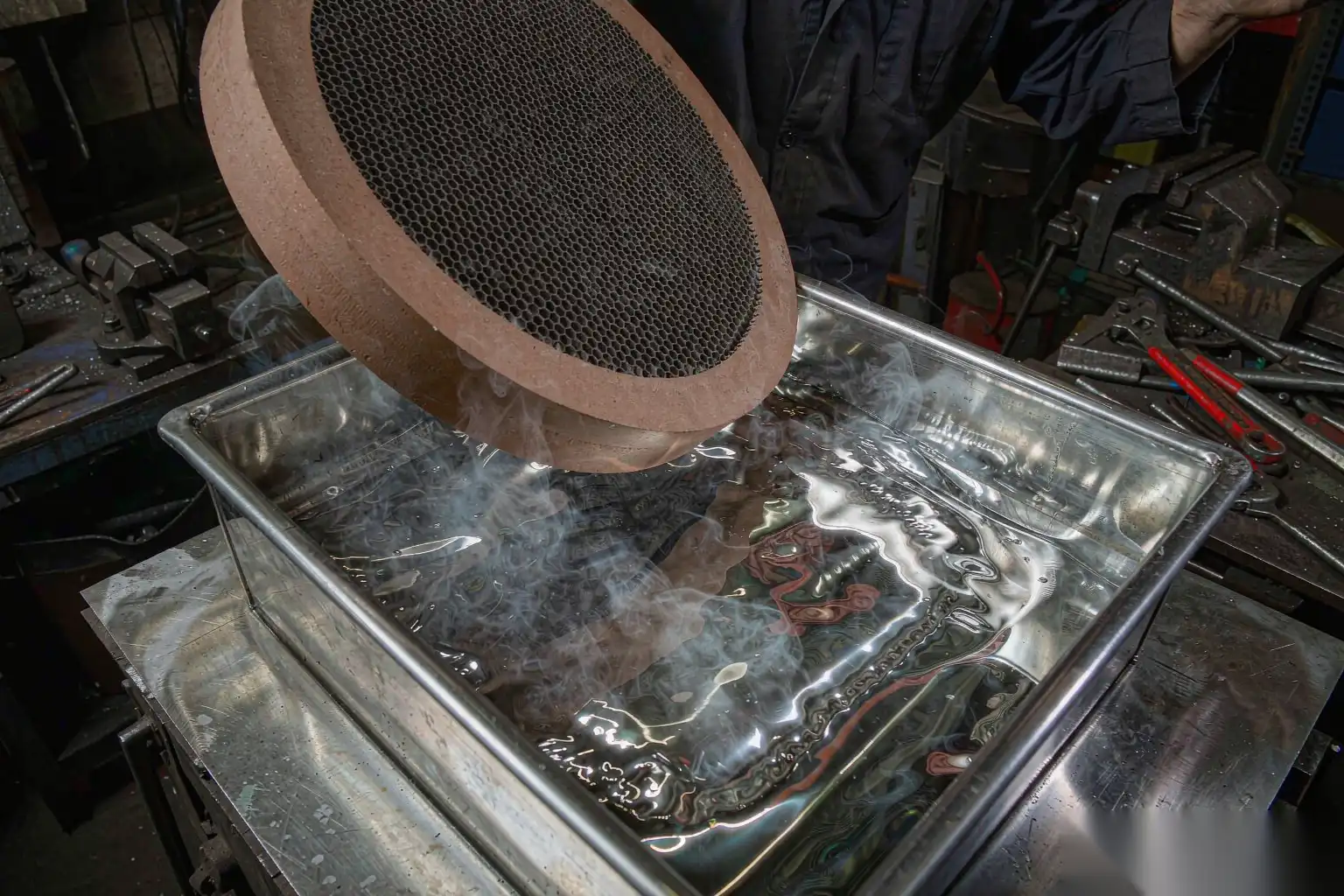
There is no perfect shop floor hydrogen test. Choose one, standardise the procedure, and trend it.
| Method | What it gives | Realistic targets | Resolution and caveats |
|---|---|---|---|
| Density index (Straube-Pfeiffer), solidified in air versus under vacuum | Relative gas level, expressed as a percentage | ≤1 percent for cosmetic or pressure-tight parts; 1 to 2 percent acceptable for general parts; above 3 percent expect trouble | Excellent as a comparative measure; procedure dependent. Standardise sample mass, mould type, cooling time and vacuum level. Requires careful weighing |
| Visual reduced pressure test (RPT) | Qualitative — pore count and distribution on the sectioned sample | No connected porosity visible at 10× ; scattered fine pores acceptable | Fast and cheap; useful for shift floor checks; subjective unless you photograph against a reference chart |
| Telegas / recirculating carrier gas probe | Absolute dissolved hydrogen in mL per 100 g | Below 0.12 mL/100 g for critical parts; 0.12 to 0.18 acceptable; above 0.25 expect porosity | Robust instrument but slow (typically 5 to 15 min per reading), fragile probe, needs disciplined technique |
| Newer continuous electrochemical sensors | Trend data at the furnace | Same numeric targets | Lower maintenance, check calibration interval and drift against a standard method monthly |
For reference, converting between them is not reliable, so do not try. Pick density index as the daily production measure and a Telegas-type absolute measurement as the monthly audit. What matters is that the daily number is taken the same way, at the same time, from the same place, and charted.
Expect re-gassing after treatment. Once you stop treating, an undisturbed furnace with a good lid will typically pick up something in the order of 0.01 to 0.05 mL per 100 g per hour depending on covering practices, humidity, and exposed surface area. That is why degassing is worth doing close to the point of use, and why an overnight hold erases the previous evening’s treatment.
Rotary Degassing: Parameter Windows That Work
Rotary degassing remains the standard control because it works, it is cheap, and it does not introduce salt. It removes hydrogen by passing inert gas through the melt as a fine dispersion of bubbles; hydrogen diffuses into the bubbles and they float out.
Equipment: a graphite shaft and impeller driven by a variable speed motor, fed with argon or nitrogen, mounted either on the furnace or on a mobile unit servicing transfer ladles. Crucible and ladle sized units typically use impellers of 100 to 200 mm diameter.
| Parameter | Typical working window | What happens outside the window |
|---|---|---|
| Rotor speed | 250 to 500 rpm (most production runs 300 to 450) | Too low gives coarse bubbles and poor dispersion; too high creates a deep vortex that folds surface oxide into the melt and accelerates hydrogen pickup |
| Rotor immersion | At least 100 to 150 mm below the surface, and no closer than 150 mm to the floor | Too shallow pumps air in via the vortex; too close to the floor erodes refractory and stirs settled sludge back up |
| Rotor position | Off-centre and tilted roughly 5 to 15 degrees | On-centre rotors create a stable single vortex and poor bubble residence time |
| Gas flow | 15 to 40 NL/min for a 500 to 1000 kg bath; commonly 0.3 to 0.8 Nm³ of gas per tonne treated | Too low extends treatment time beyond usefulness; too high wastes gas and can cause excessive surface turbulence |
| Bath temperature | 700 to 740 °C for ADC12-type alloys | Above roughly 750 °C hydrogen pickup accelerates and oxide formation increases; below about 690 °C viscosity and dross separation worsen |
| Treatment time | 8 to 20 min; diminishing returns beyond about 15 min | Under-treated leaves hydrogen; over-treated loses 3 to 10 °C and increases oxide generation without further benefit |
| Achievable reduction | Typically 60 to 80 percent of dissolved hydrogen, e.g. 0.32 down to 0.10 mL/100 g | Depends far more on rotor condition and bubble dispersion than on duration |
Operational points that get missed and cost money:
- Preheat the rotor. A cold graphite shaft lowered into aluminium can crack or spall. Warm it above the bath for 10 to 15 minutes before every treatment, and keep it above the bath between treatments so dross does not freeze onto it.
- Skim before degassing, not only after. Starting with a heavy dross blanket wastes most of the bubble surface area.
- Check the impeller weekly. A worn or chipped impeller loses dispersion efficiency long before anyone notices visually. Log hours or tonnage and replace on a schedule; graphite rotors commonly last 500 to 1500 operating hours depending on duty.
- Nitrogen versus argon. Nitrogen is cheaper and works acceptably for aluminium below roughly 760 °C; argon avoids any risk of nitride formation and is safer at higher temperatures. Choose deliberately rather than by price alone; the difference in total cost per tonne is usually smaller than the value of consistency.
Flux: When It Helps and What It Actually Costs
Refining flux serves two purposes: it strips hydrogen through a chemical reaction and it helps separate oxide from metal so inclusions can be skimmed. Typical additions are 0.1 to 0.3 percent of melt weight, injected through the lance or rotor, or broadcast with agitation.
Reasons to use it:
- Where rotary gas alone does not reach the target within a reasonable treatment time.
- Where inclusion load from dirty returns is high and you need the flux to agglomerate oxides for skimming.
- In small ladle operations that do not have rotary equipment.
Reasons to avoid or minimise it:
- Dross volume and disposal. Flux-based treatment generates substantially more dross than inert-gas-only treatment, and much of it is salt-bearing, which affects landfill classification and cost.
- Corrosion and housekeeping. Chloride vapour attacks furnace elements, exhaust ducting and nearby electrical equipment.
- Inclusion risk. Flux carried into the casting is its own defect mechanism, and it frequently shows up as white or grey deposits that later appear at polishing.
- Operator exposure. Fume extraction and procedure discipline are required.
Storage matters more than selection. A flux drum left open in monsoon humidity is worse than no flux at all. Keep containers sealed, store indoors, use within the supplier’s shelf life, and discard anything showing caking.
Filtration: Pore Size, Capacity, and the Blinding Trade-Off
Filtration removes solid inclusions that degassing does not touch. It is the control that most directly affects leak paths and polished appearance, and it is also the control most often installed without knowing what it is doing.
| Filter type | Typical specification | Removal capability | Typical life or capacity | Best application |
|---|---|---|---|---|
| Ceramic foam filter (CFF), 20 ppi | Cell size about 2.5 mm equivalent, but filtration is depth based | Coarse inclusions and oxide films larger than roughly 100 µm in practice | Several tonnes through a 178 mm square × 50 mm element depending on load | General purpose die casting transfer |
| Ceramic foam filter, 30 ppi | Finer cell structure | Down to roughly 50 to 80 µm effective | Lower capacity, roughly two thirds of 20 ppi | Cosmetic parts, pressure-tight parts, thin walls |
| Ceramic foam filter, 50 to 80 ppi | Fine | Down to 20 to 40 µm effective | Blinding risk high unless the melt is already very clean | Special cases; needs generous filter area |
| Glass cloth / woven fibreglass mesh | 0.4 to 1.5 mm aperture | Coarse dross and refractory fragments only | One shift or until blocked | Cheap pre-filter in the launder or ladle; upstream of CFF |
| Deep bed filter (tabular alumina bed) | Graded alumina bed | Down to 10 to 20 µm | Continuous operation, weeks between changeouts | High volume continuous casting; rarely justified in jobbing HPDC |
| Bonded particle tube filter | Various | 30 to 60 µm | Several tonnes | Low pressure and gravity installations |
Practical rules:
- Size for velocity, not just for the hole. Design to a superficial filtration velocity in the range of 0.5 to 1.5 cm per second through a CFF. Overspeed yields poor capture and short life; undersized area means early blinding.
- Watch for blinding. A partially blocked filter raises the upstream metal level. If your launder or filter box floods, you have sized wrong or your upstream skimming has failed. Monitor and change proactively, not when metal stops flowing.
- Prime correctly. Filters need a metal head or preheating to start flow. Poor priming leaves part of the filter area unused and reduces both capacity and capture.
- Do not rely on the filter alone. It is a safety net. The cheapest inclusion control is calm metal transfer: pump from below the surface, keep pouring lips short, cover launders, use skim dams, and never let metal free-fall more than 100 to 150 mm.
Inclusions and Why They Become Leak Paths and Polish Defects
Not all inclusions are the same, and their downstream consequences differ.
- Oxide films and bifilms. Surface oxide forms on aluminium instantly, and any turbulence folds it into the melt as a doubled-over film. These are the most damaging because they are planar: a film lying across a wall creates a crack-like discontinuity that a pressure test finds and metallography rarely does, since it hides between grain boundaries. This is the mechanism behind most unexplained leaks in castings that otherwise look sound.
- Sludge particles. Iron, manganese and chromium-rich intermetallic that precipitates when the melt temperature is too low. Sludge factor is calculated as 1 × wt% Fe + 2 × wt% Mn + 3 × wt% Cr. Below about 1.2 the risk is low; in the 1.2 to 1.5 range you need temperature and settling discipline; above 1.5, expect hard spots that damage cutting tools and polish at a different rate from the matrix. See a380 aluminum alloy properties guide for typical iron levels and why they should be specified deliberately rather than by alloy name alone.
- Refractory spall. Fragments from crucible walls and launder linings, usually triggered by thermal cycling or mechanical damage from skimming.
- Salt inclusions. Carried flux. Highly damaging to cosmetics because they are hygroscopic and leave a visible pit or bloom at the polished surface.
- Dross and dirt. From poor transfer practice and dirty returns.
Downstream, these show up in four ways that we can quantify at the finishing cell: hard particles that tear out of the surface and leave a comet tail behind polishing; films that open as hairlines when the metal is levelled; clusters that become visible pits in the cosmetic zone; and any pinhole that was hidden under the as-cast skin. See aluminum die casting porosity causes solutions and aluminum die casting defects and solutions for the matching upstream defect catalogue.
Holding Furnace Practice
Most melt quality problems are holding furnace problems, not melting problems.
- Charge discipline. Dedicate a dry, covered charge storage area. If you must use material that has been outside, hold it above the metal line or preheat it. Never charge returns directly from a water trap or a quench tank without drying.
- Returns ratio. Keep the proportion of internal returns controlled and known. Changing it silently changes the inclusion load and hence filter life, and it is often the hidden variable behind a sudden quality change nobody can explain.
- Temperature band. Hold within ±10 °C of setpoint. Higher splits are the cheapest source of both hydrogen pickup and sludge redissolution that then precipitates later.
- Lid discipline. Close lids after every charge and never leave access doors open longer than needed. The difference in hydrogen pickup between a well-covered and poorly-covered furnace is easily measurable within one shift.
- Skimming. Skim after every charge addition and before every treatment cycle. Skim gently; vigorous skimming folds oxide in.
- Cleaning schedule. Desludge and clean walls to a defined frequency based on measured sludge build-up, not on calendar convenience. Metal-line build-up is a source of hard inclusions and refractory contamination.
When to Test: A Sampling Plan That Catches Problems
Testing once a week is worse than not testing, because it gives you a number with no correlation to the parts you scrapped.
Take measurements:
- At the start of every shift before the first parts are cast.
- After any significant charge addition, once fully melted and mixed, typically 30 to 60 minutes later.
- After any furnace lid-off intervention, transfer, or reline repair.
- Twice per shift once the process is proven stable.
- Whenever cosmetic reject rates move more than one percentage point.
Standardise the sample: same location in the furnace, same preheated spoon or ladle, same sample mould, same mass, same metal temperature, same operator where possible. Density index results are extremely sensitive to cooling rate, so a different mould or sample size changes the number even if the melt is identical. Chart every result with action limits, not just recording requirements, and require the shift leader to initial every out-of-limit event with the corrective action taken.
Acceptance Criteria Written for the Finishing Cell
Debates about melt quality end quickly when the spec is written in observable terms. Rather than specifying a hydrogen number alone, specify what must be true at the functional surface. Typical clauses we work to for cosmetic parts:
- No pores larger than 0.3 mm diameter on any polished face after finishing.
- No more than two pores in the 0.1 to 0.3 mm range per 100 cm² of cosmetic area.
- No visible elongation, comet tail or dark inclusion at 400 lux illumination viewed from 500 mm.
- Zero leaks at the specified test pressure and duration after machining, on a defined sampling plan.
- Consistent behaviour across a minimum one-hour production run, not a hand-picked sample.
Then back-map those to the melt targets: density index below 1 percent at the furnace, 30 ppi filtration into the casting ladle, degassing completed within one hour of casting, and no material charged from unverified storage. The relationship is not perfectly linear, but once you have established it empirically for your own parts, you can defend the specification and stop arguing about whether a particular pore came from melting or from polishing.
The economics are usually straightforward. For a mid-size cosmetic part, moving from 3 percent to 1 percent on polish reject is typically worth several times the cost of a correctly specified degassing and filtration setup, before you count the tool damage and the customer visits.
DZ Machinery builds robotic deburring, grinding and polishing cells with force-controlled float spindles and multi-station indexing, and we work with foundries to define incoming part acceptance before equipment is specified. If your polished parts are showing pinholes or inclusion tear-out, send us samples with the melt record from the same shift and we will help you trace it upstream.