QUICK SPECIFICATIONS
| Fixture Repeatability | Within ±0.1 mm |
| Validation Run Size | 20–50 consecutive parts |
| Target Surface Finish | Ra 0.1–0.8 µm (Application dependent) |
AT A GLANCE · A robotic polishing cell turns a manual, feel-based operation into a repeatable, programmed process. For metal castings — where gates, parting lines, and surface porosity make finishing unpredictable — a well-set-up cell is the difference between scrap and a saleable A-surface. This technical setup guide walks through the commissioning process from empty floor to validated production, step by step.
You do not need an advanced robotics degree to commission an automated cell, but you do need strict engineering discipline: define the specification, build precision tooling, prove the force control recipe, and document every parameter. Skipping steps is the number-one reason automated finishing cells underperform.
Prerequisites Before You Start
- ✓ Sample castings that represent your worst-case geometry, flash thickness, and porosity.
- ✓ A written surface finish specification (target Ra values, polish direction vector, no-burn limits).
- ✓ Floor space allocation, dry compressed air, and 3-phase electrical power at the cell location.
- ✓ A designated cell engineer or lead operator who owns program recipes and tooling maintenance.
Step-by-Step Robotic Cell Commissioning Process
Setup Pitfalls to Avoid
- Underspecified Part Fixtures: Cutting costs on hardened locators leads to casting misalignment and elevated scrap rates. Always index on structural datums.
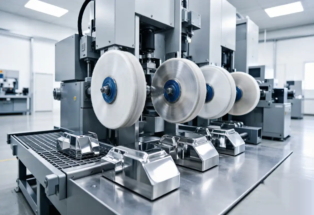
- Lack of Automated Compound Delivery: Dry polishing causes rapid wheel loading and severe thermal burn marks on alloy castings within minutes.
- Bypassing Validation Runs: Skipping structured sample runs masks process variation that later creates customer quality claims.
- Unrecorded Process Parameters: Failing to centralize recipe documentation leaves cell operation vulnerable to operator turnover.
What Good Looks Like
A properly commissioned robotic polishing cell for castings delivers consistent surface roughness (Ra) from part one through part five hundred, runs autonomously between media changes, and converts a manual labor bottleneck into a predictable, scheduled process. Master your initial cell setup, and subsequent cell installations will leverage established tooling logic and software recipes.
Safety, Guarding, and Environmental Ergonomics
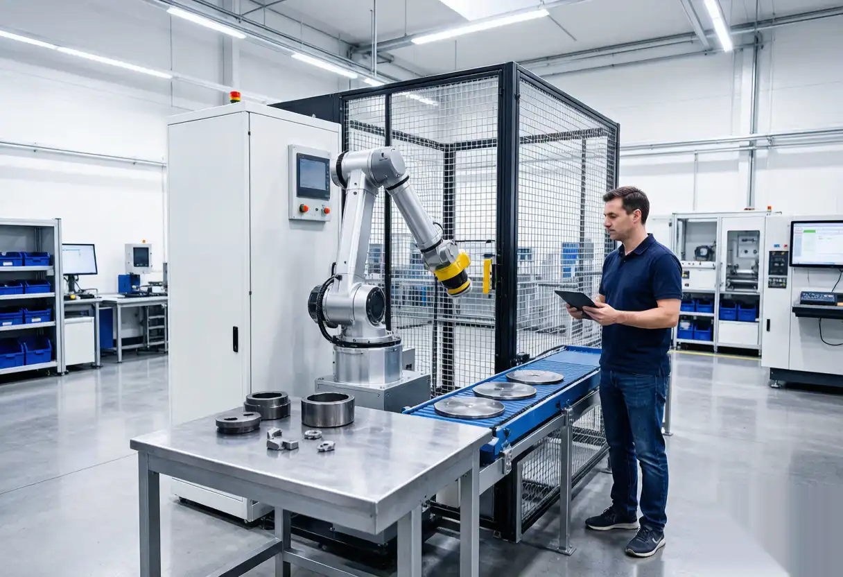
Automated metal polishing generates airborne particulates and operates high-speed articulated equipment, making physical safety systems mandatory. Fully enclose the cell with interlocked safety fencing and safety light curtains compliant with ISO standards. Position source-capture dust extraction hoods around active buffing heads to control metal dust. Automated cells eliminate repetitive physical strain, improving shop-floor safety while maintaining high production speeds.
In-Cell Maintenance During Production
Abrasive consumables set your cell uptime. Belts, flap wheels, and compound reservoirs deplete predictably based on part cycle counts. Schedule proactive media swaps before finish degradation occurs. Maintain pre-set spare fixtures near the cell for rapid part changeovers. Brief daily checks on system air pressure, extraction performance, tool wear, and fixture seating prevent unscheduled downtime and protect output quality.
Scaling From One Cell to a Production Line
Expanding automated finishing capacity relies on process standardization. Replicate proven workholding concepts for new casting SKU families, adapt saved force/speed recipe templates, and standardize cell safety controls so operators manage multiple machines seamlessly. As cell counts grow, connect equipment to central MES networks to optimize part flow and track department throughput in real time.
Metrics to Track From Day One
- Cycle Time Per Part: Verifies actual production rates against initial ROI targets.
- First-Pass Finish Yield: Quantifies surface quality consistency compared to manual operations.
- Scrap and Rework Rates: Tracks reduction in ruined castings and material waste.
- Media Consumption Rate: Identifies parameter drift or premature abrasive wear early.
- Unplanned Downtime: Isolates mechanical tool issues from upstream part variability.
Review key performance indicators weekly during initial deployment to validate cell efficiency and guide continuous optimization.
Integration With Upstream Robotic Grinding
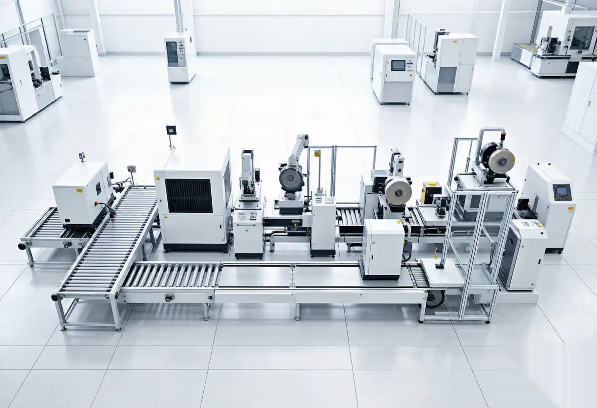
Robotic polishing cells operate most efficiently when incoming castings maintain stable geometric boundaries. Pair polishing cells with upstream automated grinding stations to remove heavy risers and flash lines consistently. Unified cell architectures can share common robot controllers and datum fixtures, streamlining casting handling from rough gate removal through high-luster surface finishing.
Troubleshooting Common Setup Issues
- Finish Varies Part to Part: Inspect fixture datum seating and force control calibration before adjusting robot toolpaths.
- Burn Marks Mid-Shift: Indicates abrasive loading; increase compound application rate and verify pneumatic line pressure.
- Missed Surface Zones: Correct path overlap distance or adjust tool approach vectors across complex contours.
- Accelerated Media Wear: Reduce contact force or adjust abrasive grit progression for the initial cutting pass.
- Cycle Time Drift: Caused by worn media; enforce scheduled abrasive changes based on component count.
Next Steps After Initial Cell Validation
Once the cell demonstrates stable target quality across continuous shifts, document production ROI data to support expanded automation budgets. Maintain version control for all software recipes and review program parameters periodically to integrate new abrasive technology.
Frequently Asked Questions
How long does robotic polishing cell commissioning take?
Fixture design and manufacturing dominate the schedule, typically requiring 1 to 3 weeks, followed by several days of robot path programming and process validation per part family.
Can a single robotic cell process different casting geometries?
Yes. By using quick-change modular fixtures and selecting stored recipes from the HMI, operators can transition between distinct part families in minutes.
Why is active force control necessary for metal castings?
Castings exhibit dimensional tolerances and surface porosity. Active force feedback dynamic compliance compensates for these variations to ensure uniform contact pressure.
What surface finish levels can automated cells achieve?
Cells achieve results ranging from gate deburring (Ra 3.2 µm) to high-mirror cosmetic finishes (Ra < 0.1 µm), determined by abrasive selection and pass sequence.
From Spec to Production — Engineering Support
Xiamen Dingzhu Intelligent Equipment designs and manufactures automated grinding and robotic polishing cells for foundries, automotive suppliers, and metal fabricators. Submit your casting dimensions, alloy specs, and target throughput to receive a custom automation proposal. Speak with our application engineering team to start your project.
References
- IEEE — Automation & Robotics Systems Standards
- CDC/NIOSH — Industrial Workplace Dust Safety Guidelines
*Product specifications and robotics standards evolve; verify latest engineering standards prior to system installation.