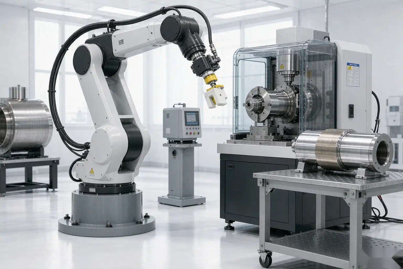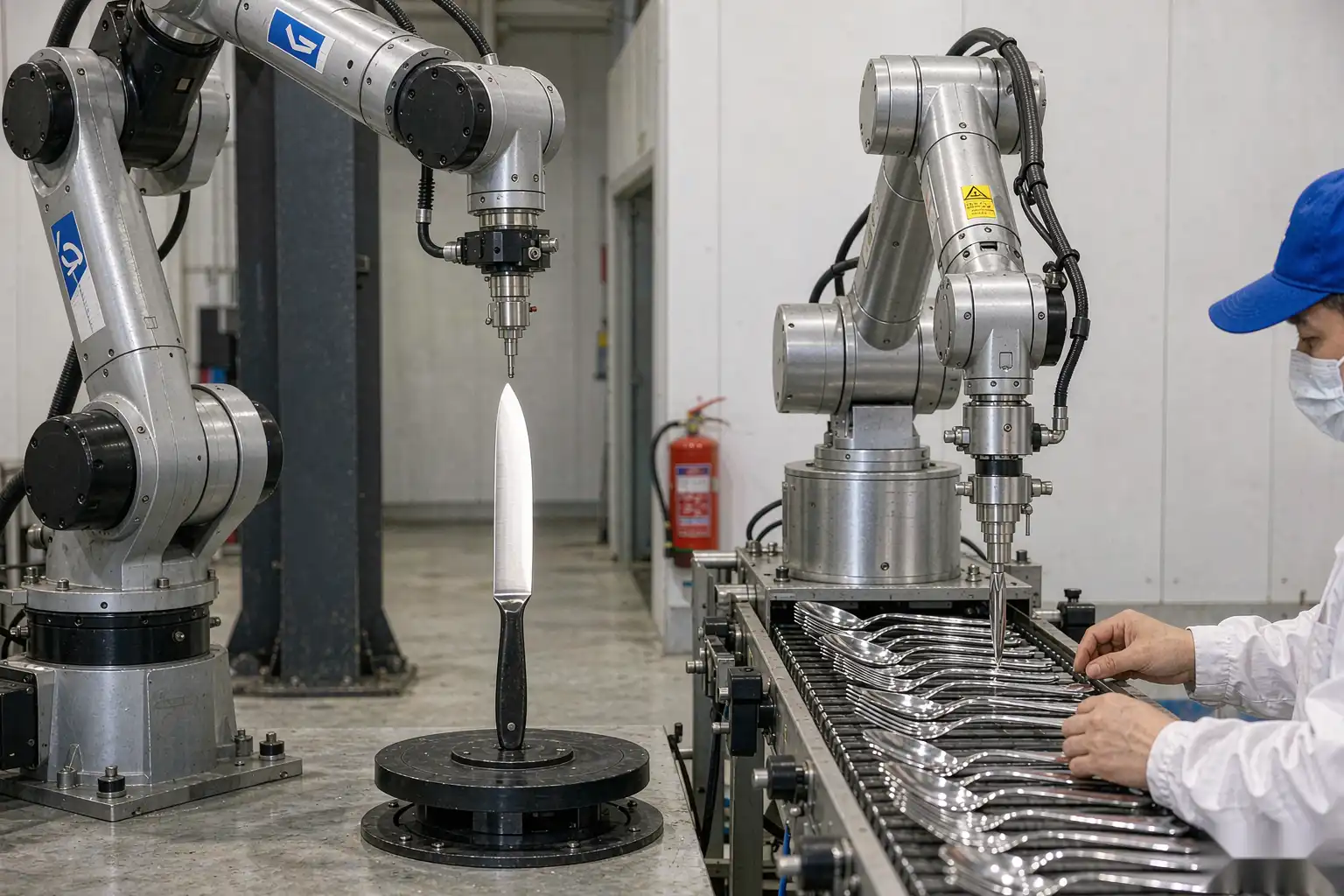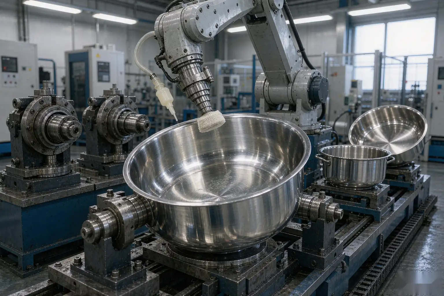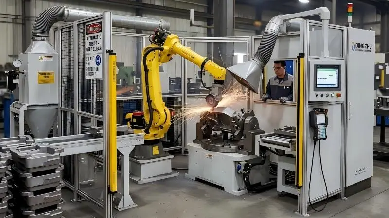
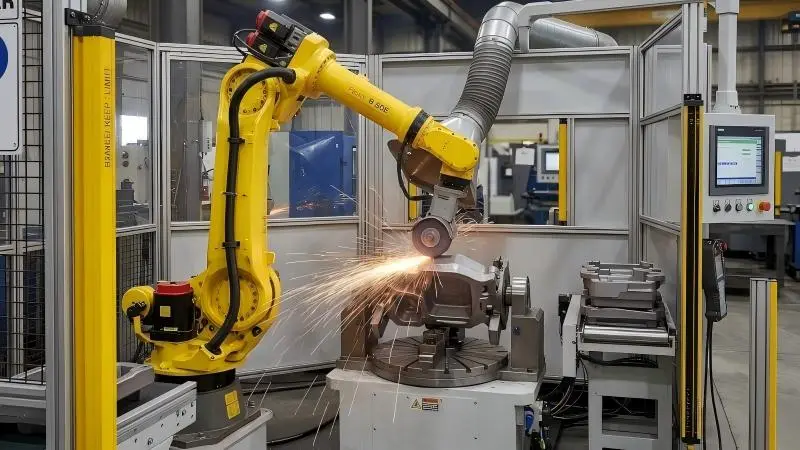
A robotic grinding cell is a self-contained, automated workstation that combines a 6-axis robot, a force-controlled grinding spindle, part fixturing, dust extraction, and a safety enclosure to remove gates, risers, and parting-line flash from metal castings without manual labor. According to the American Foundry Society, automated grinding can cut per-part finishing time by up to 60% versus hand grinding while holding edge tolerance within ±0.2 mm. For a deeper look at the machinery itself, see our robotic grinding machine guide for metal castings.
What Components Make Up a Grinding Cell
A complete cell is more than a robot holding a grinder. The standard bill of materials for a foundry-grade grinding cell includes several subsystems that must be specified together, because the cell only performs as well as its weakest link.
- Robot: a 6-axis articulated arm with 20–50 kg payload and ±0.05 mm repeatability, sized to the part weight plus fixture and tool moment.
- Spindle or grinder: a 4–11 kW electric spindle running coated or bonded abrasives at 3,000–8,000 RPM, often with a force/torque sensor at the wrist.
- Fixturing: a pneumatic or hydraulic clamp nest that locates the casting within 0.3 mm and resists grinding reaction forces up to several hundred newtons.
- Dust extraction: a downdraft table or hood rated for combustible metal dust (iron, aluminum) per NFPA 484, with spark separation upstream of the filter.
- Safety enclosure: interlocked light curtain or fencing meeting ISO 10218 for fenced cells, isolating the operator from sparks and flying debris.
- Controller & HMI: offline-programmable path generation plus a teach pendant and a simple menu for the line operator.
- Part presentation: a rotary index table, load/unload robot, or conveyor that keeps the grinding robot’s duty cycle above 85%.
In high-volume cells, a separate load robot or twin-station turntable lets the grinder run while the previous part is unclamped, which is the single biggest driver of cell utilization.
How a Grinding Cell Processes a Casting
The workflow is deterministic and repeatable. The casting arrives at the fixture and the cell closes or the robot clamps it. A vision sensor or mechanical probe confirms orientation and seating, then the arm follows a programmed path to chase the gate stub, riser contact, and parting-line flash in sequence. Force control lets the wheel compensate for casting-to-casting variation of ±1 mm without gouging the base material.
Finished parts drop to a conveyor or return tray, while swarf and dust are pulled to the extraction unit. The whole cycle for a 3 kg aluminum die casting typically runs 18–35 seconds, and for a 15 kg iron casting 40–75 seconds including clamp and unclamp. Wheel selection drives both cycle time and surface quality; our grinding wheel selection guide covers ceramic versus zirconia alumina for different alloys.
How to Set Up a Robotic Grinding Cell
Setup follows a predictable sequence, and getting the early steps right avoids days of rework later. For a step-by-step walkthrough, read our dedicated robotic grinding cell setup process.
- Define the cut plan. Map every feature to be removed and its allowable stock. Over-grind wastes wheel life; under-grind fails inspection. Document the target edge radius and tolerance band.
- Choose fixturing tolerance. Locate the part so the worst-case flash line stays within the robot’s path compensation window; a 0.3 mm locator is typical.
- Select the wheel and RPM. Match abrasive to alloy and hardness; set spindle speed for the target removal rate without burning the surface.
- Teach or import the path. Generate the trajectory offline from a CAD model, then validate on the first article before committing the program.
- Calibrate force control. Set the normal force band (typically 30–120 N) so the wheel tracks the surface without stalling or digging in.
- Run a 50-part pilot. Measure edge radius, surface finish (Ra), and wheel wear; lock the program only after process capability Cpk > 1.33.
- Train the operator. The line worker should know how to load, start, change a wheel, and clear a jam—not reprogram the path.
Grinding Cell vs. Alternative Configurations
| Factor | Robotic grinding cell | Single standalone grinder |
|---|---|---|
| Labor per shift | 0.25 operator (load only) | 1–2 operators |
| Edge tolerance | ±0.2 mm | ±0.5 mm (hand-dependent) |
| Duty cycle | 85–95% | 40–60% |
| Changeover time | 15–40 min (program swap) | 5–10 min |
| Best for | 2k–200k parts/yr | Low mix, prototypes |
Integration and Safety Notes
Treat the cell as a machine, not an island. Power, compressed air, and dust ducting must reach the footprint, and the cell controller should handshake with your MES or PLC so a full bin or filter alarm stops the line cleanly. Keep the spark path away from the load door, and never bypass the light curtain—ISO 10218 compliance is also an insurance condition.
QUICK DECISION TIP
Size the robot payload to 1.5× the heaviest casting including fixture and tool, or you will saturate the wrist axes and lose path accuracy on long gates.
ROI SNAPSHOT
A foundry replacing two hand-grinding stations (≈$90k/yr labor plus scrap) with one cell typically reaches payback in 14–22 months and cuts finishing scrap from 4% to under 1.5%.
Frequently Asked Questions
Can one cell handle multiple part numbers?
A. Yes. With quick-change fixtures and stored programs, a cell switches families in 15–40 minutes, which is why it suits high-mix production.
Do I need a vision system?
A. Only for loosely toleranced or randomly oriented castings. Fixed fixtures with mechanical locators are cheaper and more repeatable when the gate position is consistent.
What maintenance does the cell need?
A. Daily wheel dressing, weekly filter checks on the extractor, and monthly robot joint lubrication. See our maintenance guide.
Is force control mandatory?
A. For castings with ±1 mm variation, yes—without it you either gouge or leave flash. Constant-force spindles are the norm in modern cells.
Need help specifying the right machine?
Contact Xiamen Dingzhu Intelligent Equipment — we size deburring and grinding cells to your castings, volume, and tolerances. Talk to our application engineers.
References
- American Foundry Society — afsinc.org
- NADCA — nadca.com
- ISO 10218 (robot safety) — iso.org
This article is for general guidance only and does not constitute a specification or quote. Confirm process parameters with the equipment supplier for your parts.