Robotic Finishing Fixture Design: Holding Castings That Never Sit Still
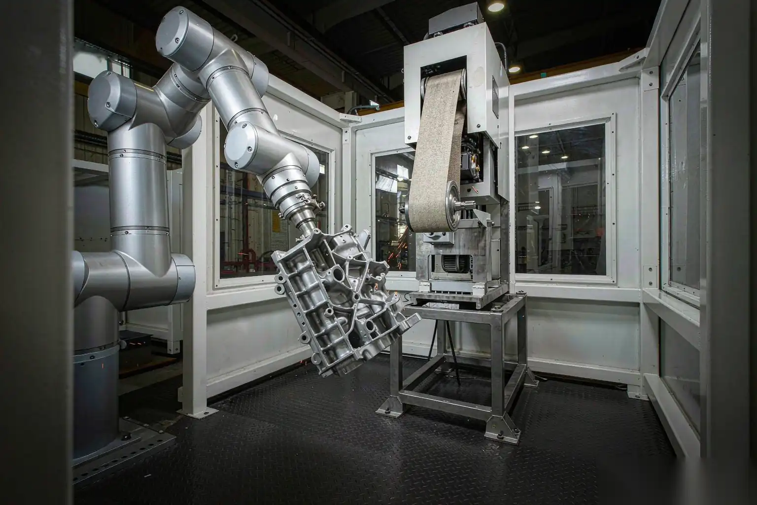
A finishing cell is only as repeatable as the thing that holds the part. We have commissioned cells where the robot, spindle and media were essentially perfect and the cell still missed tolerance every afternoon, because the fixture let a 320 mm housing rotate 0.4 mm between morning and evening as the die heated up. Robotic finishing fixture design is where most of the risk in an automated deburring, grinding or polishing project actually lives, and it is the part that gets the least engineering time.
This article covers the locating, clamping, quick-change and compensation decisions we make when a fixture has to hold a die casting or a zinc faucet body through a grinding and polishing cycle, with the numbers we hold ourselves to and the failure modes we check for before a fixture is released to production.
Why the fixture sets the ceiling on finishing quality
A six-axis robot repeats to roughly 0.05-0.10 mm under ISO 9283 conditions. A force-controlled floating spindle holds normal force inside a band of about 2-5 N. Neither of those numbers matters if the part is somewhere else than the path thinks it is.
Three mechanisms convert fixture error into scrap:
- Locating error moves the whole part in the work envelope, so the tool cuts air on one side and digs 0.6 mm on the other.
- Compliance error lets the part deflect under tool force, so the wall springs away from the abrasive and the burr survives while the surrounding surface is thinned.
- Clamping distortion holds the part in a stressed shape, releases it after finishing, and the part springs back to a geometry that was never measured in the cell.
Everything below is about attacking those three.
Locating principles for castings with draft and datum shift
Choose datums the casting actually controls
On a machined part, datums are a drawing decision. On a casting, datums are a process decision. The datum features you pick must be produced by the same die half, in the same shot, with the shortest dimensional chain to the edges you are finishing. Practical rules we apply:
- Take the primary datum from the largest flat area on the cover half of the die, because cover-half geometry is more stable than ejector-half geometry when ejector pins wear.
- Use cored holes as secondary and tertiary datums only if the core is a fixed core, not a moving slide. Slide-produced holes routinely move 0.2-0.5 mm over a die’s life as the slide wears.
- Never locate on the parting line itself. The parting line carries flash, and flash thickness varies from 0.05 mm on a tight die to 0.4 mm on a die near the end of its maintenance interval.
- Keep the datum chain to the finished edge under three features. Every additional link adds its own tolerance band.
If the drawing datums are unusable, that is a conversation to have with the tooling engineer before the fixture is designed, not after the cell is installed. Re-cutting a die to add two 3 mm locator pads on non-cosmetic surfaces is usually a one-week job and saves months of arguing about capability.
Draft is the enemy of a positive locator
Die castings carry 1-3 degrees of draft, zinc sometimes as low as 0.5 degrees. A flat locator pad touching a drafted wall makes line contact and the part rocks. Two ways out:
- Spherical or crowned contact pads. A 10-25 mm radius crowned pad on a drafted surface gives near-point contact with a repeatable centre. Three pads replace a plane.
- Nesting at the base, not the walls. Cast the locator engagement on a non-drafted, machined or post-machined pad. Where the part already gets a CNC operation, take the fixture datum from the same pad the CNC uses, so both processes see the same reference.
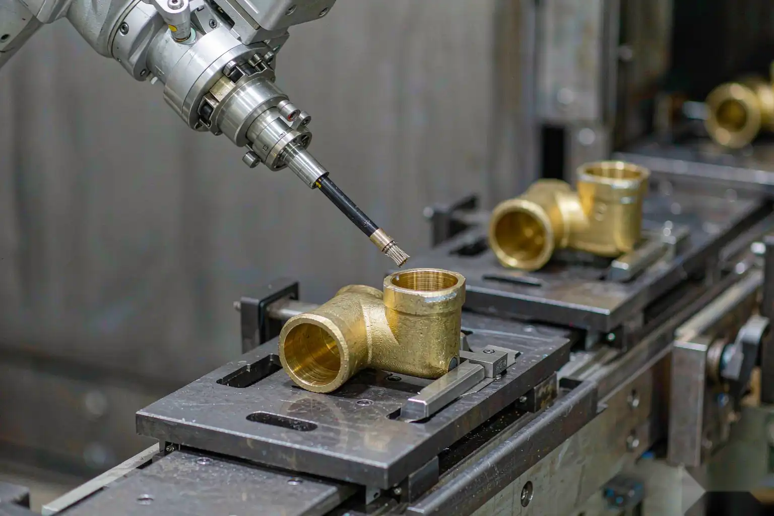
For zinc faucet bodies we routinely fixture on the machined inlet face plus two opposing cast bosses, and we ask the customer to hold the boss-to-inlet dimension to 0.15 mm. Where that is not possible, one spring-loaded floating locator with 3-5 mm of travel and 40-80 N of preload absorbs the variation without losing control of rotation.
How much variation a fixture must tolerate
Anything the casting process can throw at the part, the fixture has to either absorb or reject. Here is the budget we build to for a mid-size aluminium part, 250-400 mm envelope, before any machining.
| Variation source | Typical magnitude (aluminium HPDC) | Typical magnitude (zinc) | Fixture response |
|---|---|---|---|
| Die half mismatch / parting shift | 0.10-0.35 mm | 0.05-0.15 mm | Absorb with crowned pads and one-way locators |
| Trim die cut variation | 0.20-0.60 mm on gate and flash line | 0.10-0.30 mm | Do not locate on trimmed surfaces |
| Thermal growth, part at 25 C vs 70 C | 0.20-0.30 mm over 300 mm | 0.12-0.20 mm | Cool to 35 C before the cell or compensate with a temperature probe |
| Ejector pin push-out distortion | 0.10-0.40 mm on thin walls | 0.05-0.20 mm | Support under ejector marks |
| Die wear over 80,000 shots | 0.15-0.40 mm on slide features | 0.05-0.15 mm | Design locators with 1 mm shim adjustment |
| Batch-to-batch shrink / alloy change | 0.10-0.25 mm | 0.05-0.10 mm | Annual re-qualification of the nest |
Two behaviours follow from this table. First, no rigid fixture designed to nominal survives a quarter of die life; you need shimmed, adjustable locators with 1-2 mm of range and a locking method that cannot walk. Second, a fixture that absorbs everything produces a part that is located nowhere. There is a deliberate split: locate hard on two features, float on the rest. We aim for nest repeatability of 0.05 mm total indicator reading over 30 load-unload cycles, measured on the features that matter to the finishing path, and we verify it with a dial indicator on the actual casting, not on a gauge block.
Part temperature deserves a specific note. Aluminium expands at about 21-23 µm/m·K. A 300 mm part that enters the fixture at 70 C straight off the trim press and cools to 30 C in the cell will shrink roughly 0.25 mm during the cycle. If the grinding pass runs first and the polishing pass runs four minutes later, the two passes see different parts. Either normalise to ambient, which is what we recommend, or sequence the heavy stock removal last.
Clamping strategy and force levels that do not distort
The clamp has exactly one job: keep the part on the locators through the worst tool force the cell will ever see. Everything else about it is risk.
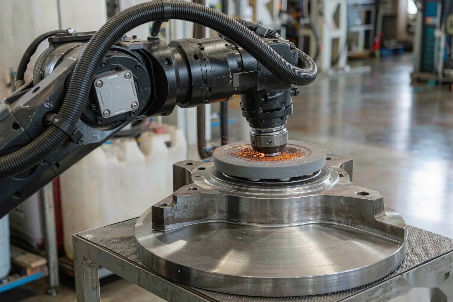
Force budget. For a spindle running a 100 mm contact wheel at 1800-2200 rpm with 40-80 N of normal force and a friction coefficient around 0.4-0.6 on aluminium, tangential force at the part is roughly 25-50 N and the overturning moment about the locator plane is what you must resist. We size clamps for a 3x margin on the calculated reaction, which for most die cast and zinc parts lands in these ranges:
- Small zinc hardware (lever, escutcheon, 60-150 mm): 150-400 N total clamp force, two or three clamp points.
- Medium aluminium housing (250-400 mm): 400-1200 N total clamp force, three or four clamp points.
- Large structural casting (500-800 mm): 1200-2500 N, four to six clamp points, often with a swing clamp plus a support jack under each clamp.
Distortion limits. Casting walls for faucet and hardware parts run 1.5-3.0 mm. Contact pressure on an unsupported 2 mm wall above roughly 1.0 MPa visibly dimples the surface, and above 1.5 MPa you can crack a zinc part at a radius. Spread the load: clamp pads of 15-25 mm diameter, or a full-width bar clamp on a rib.
Placement rules that prevent most distortion complaints:
- Clamp directly over a locator, or within 15 mm of one. A clamp in the middle of a span turns the part into a beam.
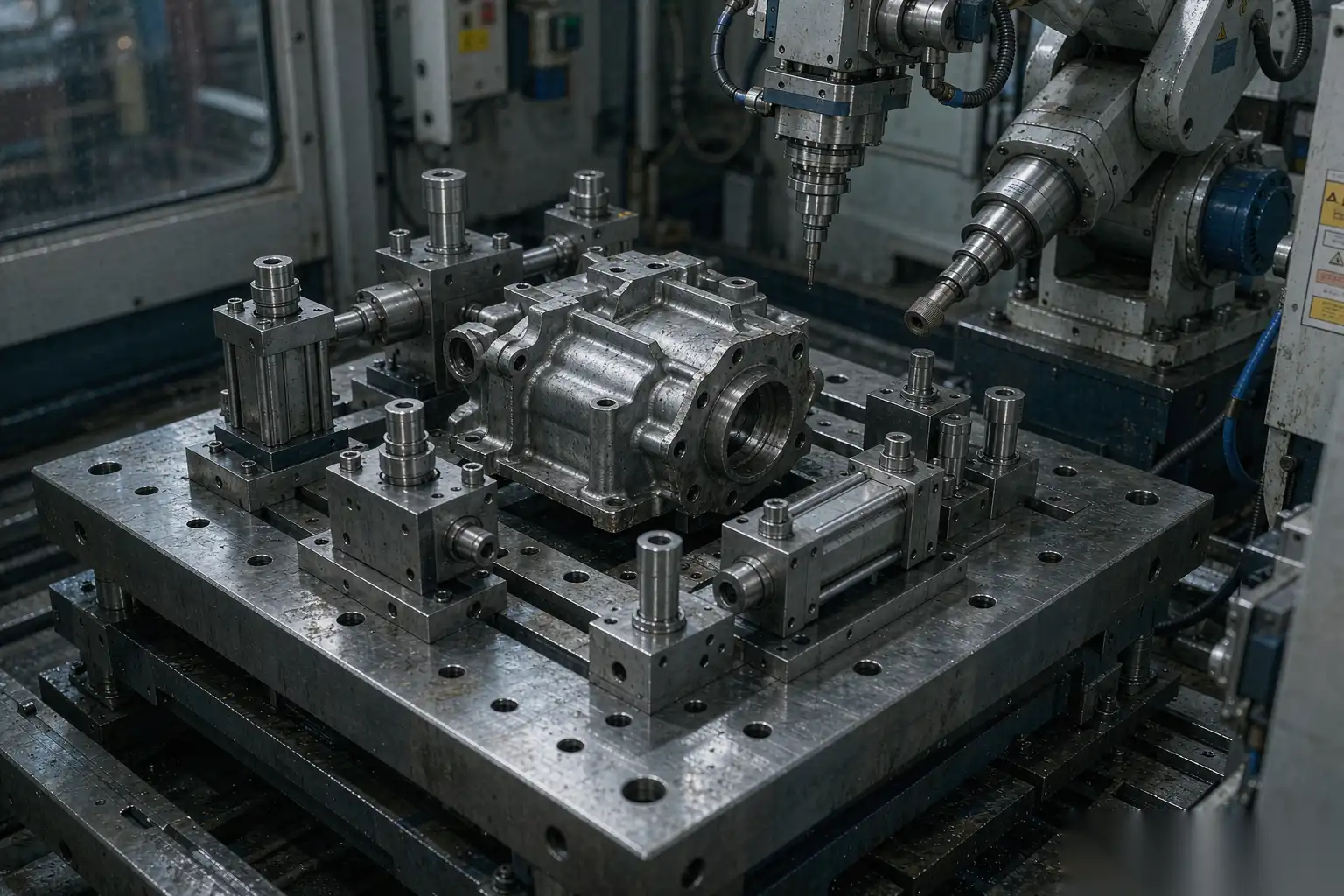
- Support ribs and bosses from below with a fixed jack before the clamp comes down, so the clamp does not bend the floor of the casting into the fixture.
- Clamp on non-cosmetic surfaces, or on surfaces that get polished later in the same cycle. A clamp mark on a class-A polished face is a reject.
- Keep clamps out of the tool approach cone. A clamp that the spindle must dodge costs cycle time and forces awkward wrist angles.
Actuation. Pneumatic swing clamps at 0.4-0.6 MPa are the default for dry grinding cells; they are cheap, fast and easy to interlock. Where the cell runs wet or with polishing compound, use stainless bodies, IP65-plus sensors and drains at the low point. Hydraulic clamps are only worth it above about 2000 N. For very light parts, a vacuum nest with 60-80 kPa and four suction cups is faster than any mechanical clamp, provided the casting back face is flat enough to seal; we require a 0.3 mm flatness band on the sealing face.
Quick-change plates and tooling repeatability
Most finishing cells run part families, not single parts. A faucet plant may run 12 bodies through one cell; a die caster may run six housings. Changeover time decides whether the cell is economical at that mix.
The mechanical interface we standardise on:
- Zero-point or H7 pin-and-bush coupling on a 200-400 mm bolt circle, giving plate-to-plate repeatability of 0.010-0.020 mm measured at the tooling reference pins.
- Air and sensor pass-through in the base plate, so a fixture plate docks with one pneumatic connection and one electrical connector; target under 20 seconds of physical swap.
- Mechanical keying so a plate cannot be docked 180 degrees out. Sounds trivial; it is the most common first-week commissioning error.
- Tooling ID via a coded pin, RFID tag or a simple resistor in the connector, so the robot controller loads the correct program. Program-to-plate mismatch is a crash, not a bad part.
Repeatability measurement matters more than the number in the catalogue. We measure the same three points on a production casting, load and unload 30 times, and take the spread. Acceptance for a grinding nest is 0.05 mm; for a polishing nest on cosmetic parts, 0.03 mm, because a polishing pass has no stock removal to hide error. Plates are re-qualified every 3-6 months or every 250,000 cycles, whichever comes first, and after any crash.
Changeover target for a well-designed family: plate swap under 60 seconds, program select under 30 seconds, first-part verification in under five minutes including a gauge check. That is what makes a two-shift cell viable at a 12-part mix.
Fixture materials and wear surfaces
Grinding dust is abrasive, conductive and, with aluminium, potentially explosive. The fixture lives in that environment.
- Locators and nests: 4140 pre-hard or tool steel, hardened to 40-48 HRC for aluminium, 52-58 HRC where the locator sees sliding. Zinc parts are less abrasive, so 30-35 HRC is acceptable. Replaceable locator buttons on 2 mm shims keep adjustment simple.
- Wear surfaces in the dust path: hard-chrome or a sacrificial 2 mm stainless cover. A locator that wears 0.05 mm in a month is a capability problem that looks like a robot problem.
- Non-contact surfaces: 6082 or 6061 aluminium plate for the fixture body keeps weight down, which matters because robot payload and plate mass trade directly against each other.
- Sealing and bearings: anything with a sliding bearing within 500 mm of the grinding point needs a labyrinth or a bellows. Standard linear bearings in an aluminium dust environment fail in weeks.
- Corrosion: with wet polishing or water-based compound, use stainless fasteners and drain paths; mild-steel fasteners rust solid and then the locator cannot be shimmed.
Extraction is part of the fixture, not an accessory. The nest should not create dead pockets where dust collects. We look for a capture velocity of 0.5-1.0 m/s at the tool contact point and shroud the nest so the airflow passes over the part rather than around it. Where the cell grinds aluminium, the fixture design review includes the dust collection and deflagration review, because a fixture that traps dust in a box is a hazard regardless of how well it locates.
Robot reach, interference envelopes and station layout
Fixture geometry decides wrist angles, and wrist angles decide cycle time and spindle life.
Practical layout rules:
- Keep the finish zone inside 60-75 percent of the robot’s maximum reach. At full extension you lose stiffness and the path repeatability degrades; a 0.05 mm robot becomes a 0.15 mm robot.
- Maintain 50 mm minimum clearance between the spindle body and the nearest clamp or fixture column through the entire path, verified in offline simulation with the actual tool model including the nut, flange and dust shroud.
- Limit wrist articulation to roughly ±100 degrees on axes 5 and 6 in the working path. Extreme wrist angles shorten cable life and push the tool’s centre of gravity outside the rated envelope.
- Put the load station outside the robot’s ISO 13855 safety envelope or behind an interlocked door with a light curtain muting only where the part transfer is fully guarded.
- For multi-station turntables, keep station mass within 10 percent across the table so the index does not fight an unbalanced load.
Part presentation also decides whether you need a servo positioner. If the casting must be finished on five faces and the features are more than 120 degrees apart, a one-axis servo positioner on the fixture table is usually cheaper than a robot contortion, and it improves the tool approach angle, which directly improves surface finish consistency.
Closing the loop: media wear compensation and path repeatability
Abrasive media is the largest uncontrolled variable after the fixture. Belt and flap wheel behaviour over life:
- A new zirconia belt cuts aggressively and runs cool; after 20-30 minutes on aluminium it glazes, cut rate drops 30-50 percent and the part heats.
- Flap wheels lose diameter continuously; a 100 mm wheel down to 92 mm changes contact geometry and effective surface speed by 8 percent.
- Buffing wheels load with compound; a loaded wheel polishes inconsistently and leaves compound residue inside recesses.
Compensation methods, in increasing order of capability:
- Time-based tool change at a fixed interval derived from a worn-tool capability study. Simple, and adequate for rough deburring with 0.3 mm tolerance.
- Force-controlled floating spindle with a closed force window. A floating head holding 50 N ±3 N gives far more consistent stock removal than a position-controlled path, because it tracks part variation as well as media wear.
- Automatic tool change with diameter measurement, where the spindle rack carries four to eight heads and the controller offsets for measured wheel diameter. Needed for polishing cells that run unattended for a shift.
- In-process gauging, either a probe on the robot or a station gauge measuring one critical dimension every N parts, feeding an offset back to the path. Worth it only above roughly 30,000 parts per year on a tight feature.
Path verification should be a scheduled activity, not a reaction to scrap. We run a check part through the cell at the start of every shift, measure three dimensions, and log them. Drift beyond 0.05 mm on a grinding cell or 0.03 mm on a polishing cell triggers a fixture locator check before anyone touches the robot program. That discipline finds worn locators and unbalanced tables long before the quality department does.
For context on the upstream process capability you are fixturing against, see aluminum die casting tolerances, and for the cell architecture itself, how automatic deburring machines work for castings.
Fixture design checklist
Before a fixture is released to production, we require every item below to be answered with a number, not a yes.
- Primary, secondary and tertiary datums identified on the die drawing, with the die half noted for each.
- Locator type and contact radius for every drafted surface; no flat pad on a drafted wall.
- Design variation budget per feature, with the largest expected total listed and the fixture range exceeding it by 1.5x.
- Shim range on every adjustable locator, minimum 1 mm, with a locking method that survives vibration.
- Clamp count, total force, and contact pressure on the thinnest wall, calculated not guessed.
- Clamp reaction against worst-case tool force with a 3x margin.
- Distortion check: measure the part in the fixture, release it, and re-measure. Acceptance under 0.05 mm on critical features.
- Nest repeatability over 30 cycles, on production castings, measured and recorded.
- Quick-change interface repeatability, tooling ID method, keying feature.
- Changeover time measured with the actual operator, not the engineer.
- Interference check in simulation with full tool model, 50 mm clearance, at the extremes of the path.
- Dust capture velocity at the tool point and drain paths in the fixture.
- Media life per tool, compensation method, and the offset mechanism.
- Shift-start check part, dimensions measured, control chart opened.
The last question is who owns the fixture design, because a fixture designed by a robot integrator that has never seen the die drawing is a fixture you will rebuild.
DZ Machinery designs and builds the cell around the part family, not the part. That means the fixture, the robot cell layout, the spindle package, the dust extraction and the cycle time calculation are engineered together, with fixture plates and nests built for the family so a new variant is a plate and a program rather than a new project. If you are planning a finishing cell for die cast housings, zinc faucet bodies or hardware components, send us the part drawings and the annual volume, and our engineering team will come back with a fixture concept, a station layout and a cycle time and yield estimate you can check against your own numbers.