Insert Die Casting Design Guide: Retention, Preheat, and Bond Inspection
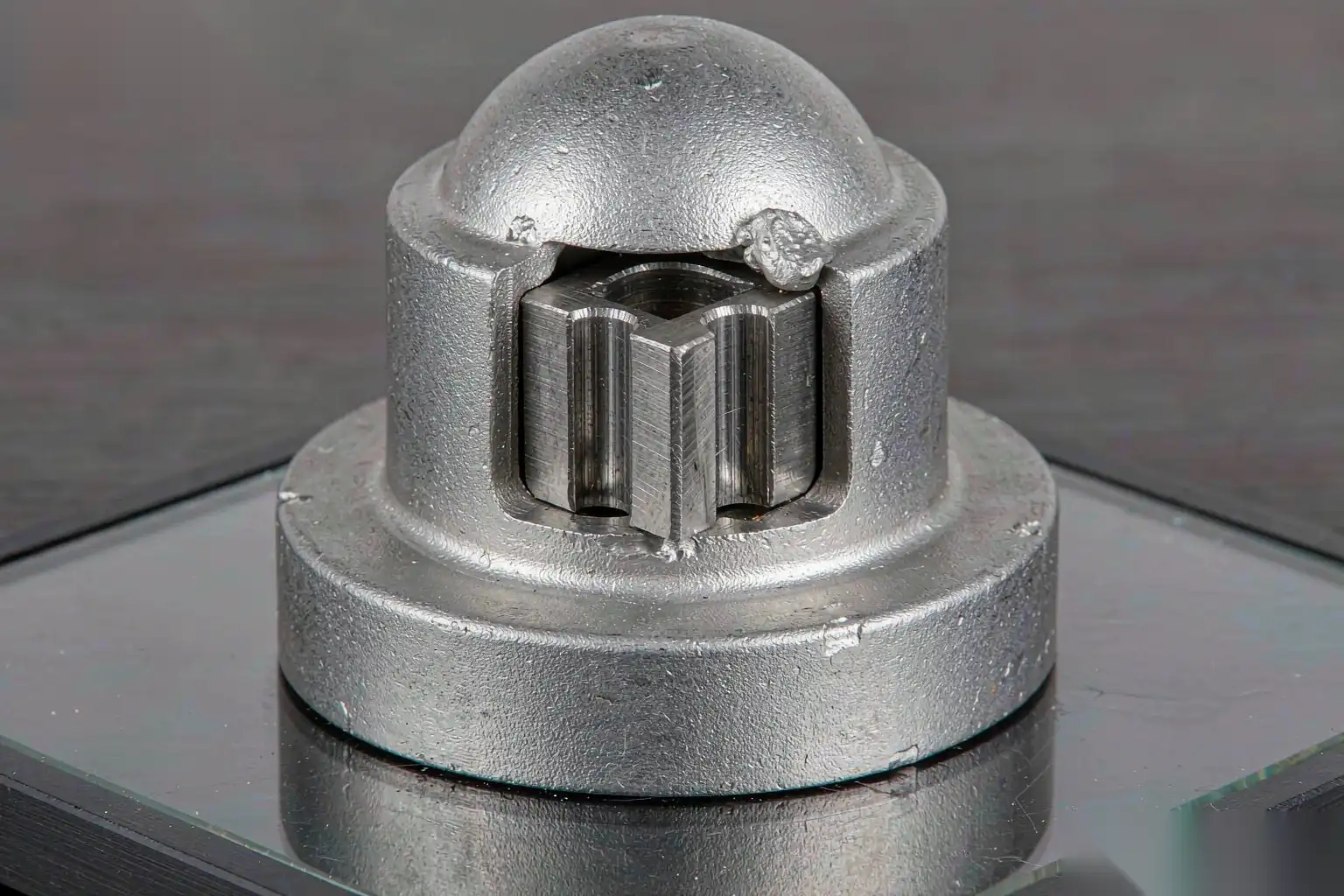
Casting metal around a pre-placed insert is one of the most useful and most abused techniques in die casting. Done well it removes an assembly operation, gives you a thread or bearing surface far stronger than anything cast directly, and cuts part count. Done badly it produces castings with loose bushings, cracked bosses, a corrosion path you cannot see, and a scrap rate that nobody can stabilise.
We deal with the downstream consequences constantly: a faucet body with a cast-in stainless seat, a hardware handle with a steel threaded insert, a housing with a bearing race. When those come to us for automated grinding and polishing, the quality of the insert bond decides whether the finishing cell runs at 98 percent yield or struggles at 80 percent.
This guide covers insert preparation, retention geometry, thermal mismatch and preheat, the real cycle time penalty, die design and loading methods, the failure modes we see most, and how to inspect a bond that you cannot see.
Why Cast Around an Insert
The justification is usually one of four:
- Wear or load requirement. Cast aluminium threads strip. A steel threaded insert in a frequently assembled joint, or a bearing race under radial load, survives where the parent alloy would not.
- Assembly elimination. Pressing a bushing after casting costs a station, a press, a fixture and an inspection step. Casting it in removes all of them.
- Geometry that cannot be cast. Internal threads, undercut grooves, and tight-tolerance bores are cheaper to make in steel and then cast around.
- Function. Heating elements, sensor sleeves, and electrical contacts are cast in because that is the only way to get the function into the part.
The counter-argument is always the same, and it should be stated out loud in the design review: casting in an insert converts a cheap, inspectable press-fit operation into a permanent, non-inspectable bond inside an expensive casting. If the insert fails, you scrap the whole casting. That trade is only worth making when the insert failure rate in service is low and predictable.
Insert Materials and Surface Preparation
Material choice is driven by function first and by thermal and galvanic compatibility second.
- Free-cutting or leaded steel, and 12L14-type resulphurised steel. Easy to machine, widely used for bushings and threaded inserts.
- Stainless steel, 303 and 304. Used where corrosion resistance matters. Note that stainless has a thermal expansion coefficient around 16 to 18 × 10⁻⁶/K, versus roughly 21 to 23 × 10⁻⁶/K for ADC12-type aluminium. That difference is central to the design.
- Brass. Good machinability and a thermal expansion coefficient closer to aluminium than steel, around 19 to 20 × 10⁻⁶/K, which makes it a good choice where fit matters. Galvanic risk with aluminium is real and needs coating or isolation.
- Bearing steel and hardened races. Used where the insert is a running surface. Hardened inserts must be checked for tempering: exposure to 650 °C aluminium for a second or two will not through-heat a large race, but it will draw the temper on small, thin sections.
- Copper and copper alloys for heating elements. Excellent conductivity, high thermal expansion, and a serious galvanic couple with aluminium.
Surface treatments
Surface condition governs both bond quality and corrosion behaviour.
- Knurling and grooving is mechanical, not a coating. It provides the retention geometry and is covered below.
- Cleanliness is the most underrated treatment. Inserts arrive with cutting fluid, rust preventive, fingerprints and packaging residue. Any organic residue vaporises at casting temperature and produces gas at the interface, which shows up as a void ring around the insert. Vapour degrease or solvent clean, then handle with gloves, and hold cleaned inserts in a closed container with a defined shelf life of one shift.
- Plating and coating. Zinc or nickel plating can help with galvanic isolation, but check the coating’s temperature limit. A zinc layer will alloy with the aluminium melt at the surface, and a nickel layer can spall if the bond line is stressed. Tin plating on copper inserts is common for the same reason.
- Deliberate roughness. A blasted or coarse-turned surface in the range Ra 3 to 6 µm improves mechanical keying compared with a smooth machined finish. Below roughly Ra 1.6 µm the mechanical key is poor and the joint relies on shrink fit alone.
Retention Features: Knurls, Grooves, Hex, and Shoulders
Retention has to resist three loads: torque, axial pull-out, and rotation under vibration. Different geometry addresses different loads, and the common mistake is using a knurl alone and expecting it to hold torque.
| Feature | Resists | Design guidance | Typical pull-out or torque gain |
|---|---|---|---|
| Straight diamond knurl | Rotation, moderate axial | 0.8 to 1.2 mm pitch on small inserts, 1.5 mm on larger; full depth across the embedded length | Baseline; roughly 2 to 4× a smooth surface |
| Helical knurl | Rotation and axial | Preferred over diamond for combined loading | 1.2 to 1.5× diamond knurl |
| Circumferential groove | Axial pull-out strongly, weak in torsion | 1 to 2 mm wide, 0.8 to 1.5 mm deep, one to three grooves | Strongly axial, needs a second feature for torque |
| Hex or double-hex | Torque | Across-flats form, 1 to 2 flats deep | Highest torque capacity |
| Shoulder or flange | Axial in one direction | 1.5 to 3 mm wide | Positive stop, also locates the insert |
| Cross-hole or through-hole | All directions | Metal flows through and locks | Very high, but creates a stress site |
Two rules we apply. First, always combine an axial feature with a torsional feature: a groove plus a knurl, or a shoulder plus a hex. Second, design the insert so that it cannot be loaded incorrectly. An insert that is symmetrical top to bottom will eventually be loaded upside down, so make the ends different diameters or add a chamfer that only fits one way in the die.
Wall thickness around the insert is the other half of the design. Aluminium shrinks onto the insert as it cools, and that shrink fit is what actually holds the part together. If the surrounding wall is too thin, the aluminium tears instead of gripping; if it is too thick, the section becomes a hot spot and shrinkage voids form next to the insert. Working rule: surrounding wall at 0.6 to 1.0 times the insert outer diameter, and never below 2.5 mm for a steel insert under 20 mm diameter.
Thermal Expansion Mismatch and Preheat
Aluminium contracts roughly 0.5 to 0.6 percent more than steel as it cools from solidification to room temperature, depending on the alloy pair. On a 25 mm steel insert that is a diametral interference of around 30 to 50 µm, which is what generates the grip. It also generates the stress, and if the surrounding section cannot take it, the casting cracks.
Preheat is the main control, and it is the step most often skipped on the shop floor.
- Purpose. A cold insert chills the melt locally, producing a misrun or cold shut at the interface, and it produces a heavier shrink grip that can crack a thin boss. Preheating to 150 to 250 °C reduces the thermal shock and keeps the front alive around the insert.
- Method. Induction preheat is fast and repeatable and is the right choice for automated cells. A hot plate or oven batch is acceptable for low volume but gives poor repeatability. Never use an open flame, which leaves soot that becomes a bond-line defect.
- Verification. Measure the insert temperature with a contact probe or infrared at the point of loading, not the oven setpoint. Inserts cool quickly; a 200 °C insert can drop to 120 °C within 60 to 90 s in a draughty cell.
- Upper limit. Do not exceed roughly 250 °C for plated inserts, and keep the time at temperature short to avoid oxidation of the retention features, which reduces keying.
Design for the mismatch in the drawing: allow the interference to work for you by specifying surrounding wall thickness, keep the insert away from sharp external corners where stress concentrates, and avoid placing inserts within 5 mm of each other on small parts, since the stress fields overlap and crack paths link up.
Cycle Time and Cost Penalty
Insert casting is not free, and the penalty should be quantified before quoting.
- Manual loading. Placing one insert takes 3 to 8 s of operator time; four inserts means the operator is the bottleneck. Total cycle penalty is usually 15 to 40 percent over an equivalent casting without inserts.
- Verification. Loading must be confirmed before the die closes. A die protection sensor on each insert pocket adds a fraction of a second but prevents a crushed die, which is a five-figure event.
- Die maintenance. Insert pockets wear, and a worn pocket lets metal flash into it. Flash on the insert seat means the next insert does not seat fully, and then the die closes on a proud insert.
- Scrap cost. Every rejected casting now includes the cost of the inserts and the loading labour, and the inserts are not recoverable.
The honest break-even calculation compares the added casting cost against the eliminated press-fit or assembly station, plus the improved service performance. In our experience insert casting wins on volumes above roughly 20,000 pieces per year where an assembly station would otherwise exist, and it loses on low-volume, high-mix work where the die pocket changeover time dominates.
Die Design and Insert Loading Methods
Loading method drives die design, and the choice is mostly a volume decision.
Manual loading
The operator places inserts into pockets in the fixed or moving half. Design requirements:
- Pocket must hold the insert against gravity and against the die closing motion, usually with a magnet for steel, a spring detent, or a vacuum port.
- Insert must be positively located axially. A stop face that the insert shoulder registers against prevents it being pushed into the cavity by injection pressure.
- The pocket must be visible and reachable with a gloved hand with a die spray cycle in between; if it is not, the operator will find a faster way to do it.
- Provide a sensor per pocket. A proximity or air-blow-back sensor detecting insert presence costs little compared with a die crash.
Automated loading
Above roughly 50,000 pieces per year, or where multiple inserts per shot are required, automated loading pays. A bowl feeder, an escapement, and a pick-and-place unit load all inserts in 1.5 to 4 s regardless of count. Requirements:
- Inserts must be orientable by the feeder, which often means adding a flat, a chamfer, or an asymmetric feature purely for feeding.
- Dimensional consistency matters more: a bowl feeder jams on out-of-tolerance parts where a human would just try again.
- The cell needs a reject path and a miss-detection interlock.
Die design notes that apply to both cases: locate the insert on a core rather than in the cavity where possible, since cores can be replaced and reworked; provide a relief so that flash on the insert does not prevent seating; and keep the insert seat away from the gate so that the full injection pressure is not acting directly on the retention geometry at the moment of fill.
Failure Modes
These are the ones we see, roughly in order of frequency:
- Insert movement during fill. Injection pressure pushes the insert out of position. Symptom is a shifted insert or a thin wall on one side. Cause is insufficient seating force, a worn pocket, or a missing shoulder.
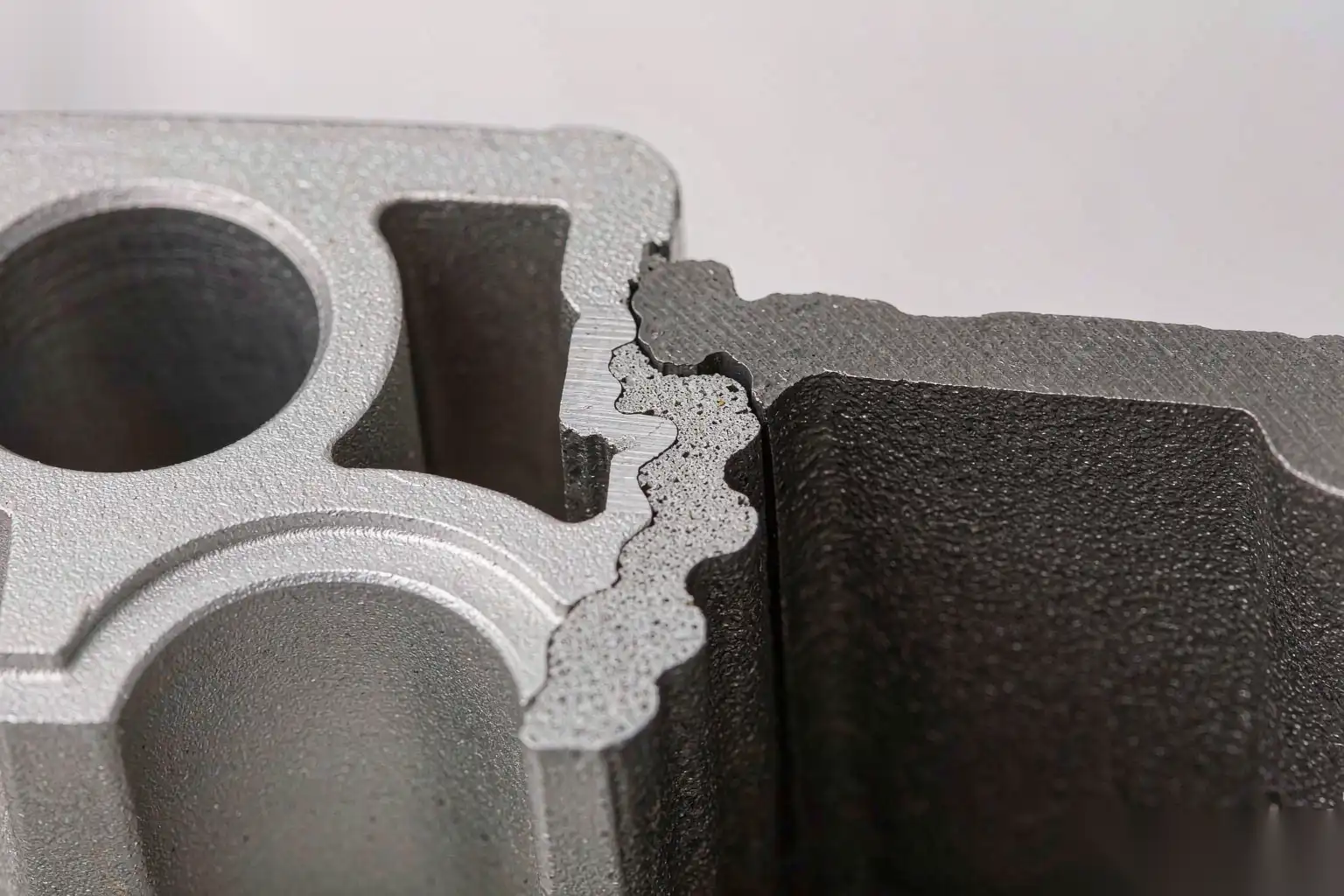
- Gap at the interface. A continuous annular gap of 0.05 to 0.3 mm, visible in section, resulting from a cold insert or contamination. The part may look perfect externally and fail a leak test or a pull-out test.
- Cracked boss. Radial cracks in the aluminium around the insert, appearing hours or days after casting. Caused by excessive interference, insufficient surrounding wall, or stress overlap between adjacent inserts.
- Galvanic corrosion. Aluminium is anodic to steel, stainless and copper. Any electrolyte at the interface starts a cell, and the corrosion product expands and cracks the boss. Mitigate with plating, sealant application after casting, or design that keeps the joint dry.
- Tempering of hardened inserts. Small hardened parts lose hardness at the bond line. Check hardness after a trial casting, not before.
- Flash into the insert bore. Metal enters a threaded hole and the thread must be chased, or the insert is scrap. Protect bores with a core pin that closes against the insert end face.
- Insert ejection damage. If the insert is in the moving half, ejector pins pushing on the insert rather than the casting will push it out. Always eject on the casting.
Inspection of the Insert Bond
The bond cannot be seen, so inspection strategy matters more than inspection frequency.
- Pull-out and torque test. Destructive, but it is the only test that gives a number. Sample rate of 1 per 500 to 1 per 2000 depending on criticality, with a defined minimum: for a typical M8 steel insert in aluminium, torque to failure above 25 to 40 N·m and axial pull-out above 8 to 12 kN are reasonable targets, but set your own from your own trials.
- Air blow or leak test through the interface. Where the insert creates a sealed cavity, a pressure decay test across the bond line catches continuous gaps non-destructively.
- X-ray. Detects gross misplacement and large interface voids, and is fast enough for higher sample rates. It does not detect a tight dry bond.
- Ultrasonic. Sensitive to interface contact and usable in production, but needs a reference standard and a trained operator.
- Sectioning. The reference method. Cut through the insert axis, polish, and measure the gap at eight points around the circumference. Acceptance: no continuous gap exceeding 0.1 mm, no gap exceeding 30 percent of the circumference.
- Dimensional check of insert position. A simple go/no-go on insert protrusion and concentricity catches the movement failure mode cheaply and catches it early.
Write the acceptance criterion into the drawing. “Insert must be secure” is not a specification, and it is the phrase that appears most often on drawings we are asked to finish parts against.
Design Rules That Survive Production
A short checklist we run before releasing an insert casting to tooling:
- Combine one torsional and one axial retention feature.
- Surrounding wall between 0.6 and 1.0 times insert diameter, minimum 2.5 mm.
- Inserts cleaned, preheated to 150 to 250 °C, and loaded within a defined time window.
- Positive axial location in the die, with a sensor on every pocket.
- Ejection on the casting, never on the insert.
- Galvanic pair reviewed, with plating or isolation specified where the joint can see moisture.
- Destructive pull-out or torque test on a defined sample plan, with the number on the drawing.
- Trial castings validated across the full die temperature range, including cold start, since cold-start parts show the worst interface quality.
Tooling decisions for insert castings interact with everything downstream. A part with four cast-in inserts has four hard spots that behave differently under an abrasive belt, and the flash and parting line condition around the insert bosses determines how much hand work survives into the finishing cell. If you are planning the casting route and the finishing route together, our notes on aluminum die casting mold design and custom aluminum die casting cover the tooling side, and aluminum die casting cost factors breaks down where insert loading shows up in piece price.
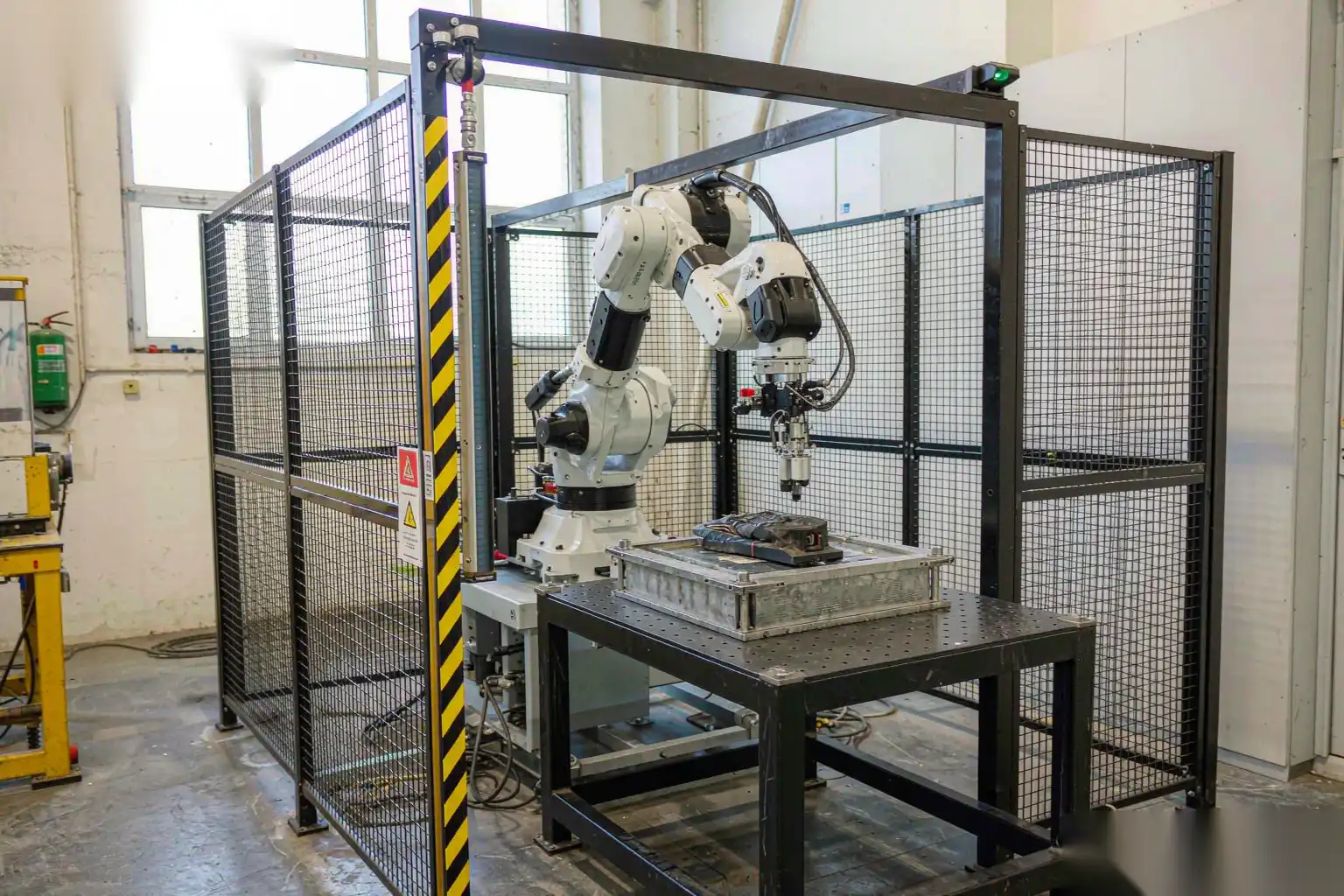
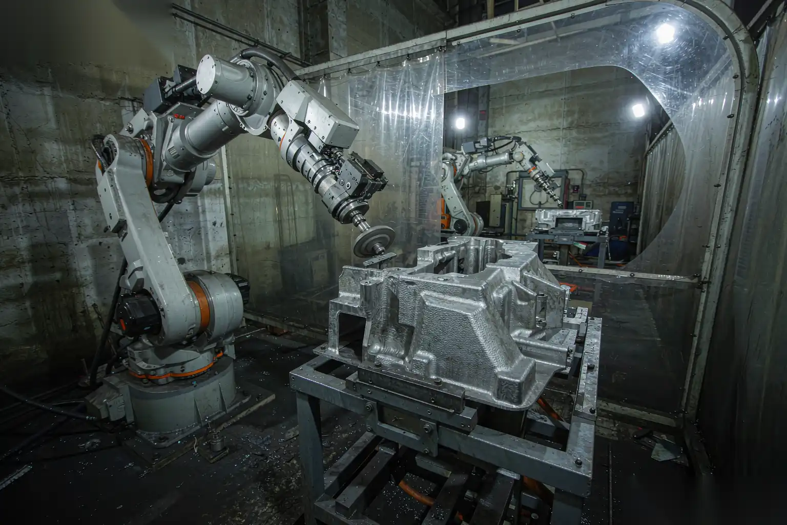
DZ Machinery builds robotic deburring, grinding and polishing cells for die cast and faucet hardware, including fixtures that locate on cast-in inserts and machine datums. If you have a part with cast-in inserts and you are planning automated finishing, send us the drawing and a sample and we will tell you what the cell needs to hold and what the achievable cycle time is.