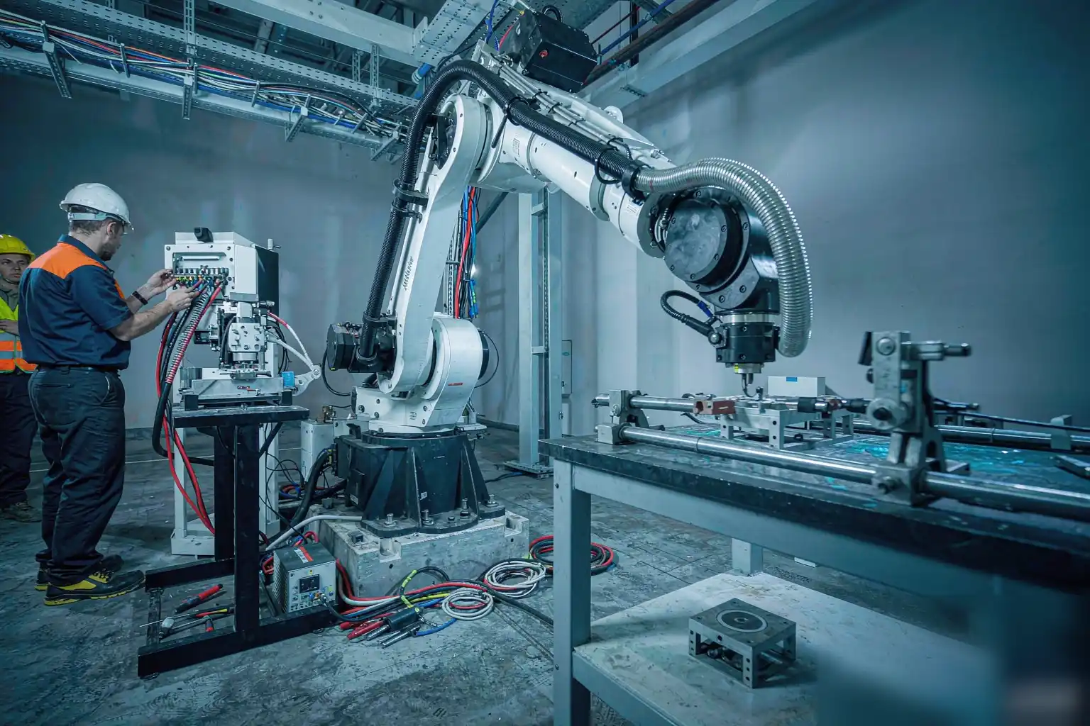
AT A GLANCE · A robotic grinding cell setup is more than bolting a robot to a bench. It is a system that combines a robot, spindle, fixture, dust control, and software into one repeatable process. Therefore, you must plan the whole line before buying hardware. First, map the parts you will grind. Second, define the finish quality you must hold. This article walks through twelve practical steps that take you from a bare floor to a running cell.

Step 1: Define Your Part Mix and Production Goals
Start by listing every part the cell must process, including material, size, and annual volume. For example, a faucet plant may run brass bodies alongside stainless hardware. Therefore, you should estimate the worst-case cycle time and the target surface roughness. Write these numbers down, because they drive every later decision. A clear production goal also helps you justify the investment to management. Review our robotic polishing cell setup guide when your mix includes cast components that need both grinding and polishing.
Step 2: Select the Right Robot Payload and Reach
Payload is the single most common mistake in a robotic grinding cell setup. The robot must lift the spindle, the tool, and the reaction forces from grinding, not just the part weight. Therefore, add a safety margin of at least thirty percent to your calculated load. Reach matters too, because the robot must cover the entire part without awkward wrist angles. However, a larger robot costs more and moves slower. Choose the smallest model that meets your envelope and stiffness needs.
Decide between a six-axis industrial arm and a cobot based on force and space, not on trend. Industrial arms give speed and rigidity for heavy castings and long shifts. Cobots suit low volumes where humans share the floor and change parts often. Therefore, match the robot class to your throughput and safety plan. Also budget for the controller, cables, and a teach pendant your team can actually use.
Step 3: Choose the Grinding Spindle and Tooling
The spindle converts robot motion into material removal, so its power and speed define your process window. Belt heads suit flat cast surfaces, while flap wheels reach contours and edges. For example, a 4 kW electric spindle handles most faucet deburring, but hard steel may need more. Therefore, match the tool to the stock removal and the finish spec. Consider your surface finishing robot integration early, because tool changers and compliance devices must fit the chosen spindle.
Step 4: Design the Fixture and Part Presentation
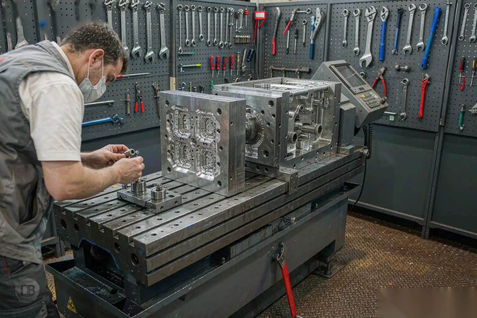
A stable fixture is what makes a robotic grinding cell setup repeatable rather than hopeful. The part must sit in the same place within a fraction of a millimeter every cycle. Therefore, use locating pins, clamps, or a quick-change nest sized to your tolerances. Second, decide how parts arrive: a turntable, conveyor, or manual load. Pneumatic clamps speed changeovers, but they add maintenance. Keep the fixture simple, because complexity here becomes downtime later.
Plan for changeover from the start, because most cells run more than one part number. A modular nest lets you swap families in minutes instead of hours. Therefore, standardize the datums so one program offset serves a whole family. Store fixtures on a rack within reach of the loader to cut idle time. Good fixture design is the cheapest insurance against drift you will ever buy.
Step 5: Integrate Dust Collection and Safety Enclosures
Grinding metal throws sparks, abrasive dust, and noise that endanger people and machines. Therefore, enclose the cell and connect a rated dust collector sized to your airflow. Use spark-resistant ducting and check local filtration rules before you order. However, the enclosure must still allow loading and vision access. Interlock the doors so the robot stops on entry. A clean cell also protects the spindle bearings, which extends tool life and cuts unplanned stops.
Step 6: Add Force Control and Compliance
Castings vary, so a rigid robot path will either miss high spots or dig into low ones. Force control lets the tool follow the surface by pushing with a set contact force. Therefore, add a compliant device or active force sensor to absorb variation. For example, a pneumatic float head keeps pressure steady on curved faucet bodies. However, too much compliance looses edge definition. Tune the gain so the tool tracks the part yet holds the geometry your quality team demands.
Step 7: Program the Grinding Path
Programming turns your hardware into a process, and it starts with a clean path, not clever code. Teach or import the part contour, then assign speeds, overlaps, and passes per region. First, rough the heavy flash with a coarse belt at high feed. Second, finish with a finer wheel at lower pressure. Therefore, build the program in layers so you can tune each zone alone. Keep waypoints smooth, because jerky motion leaves chatter marks that inspectors reject.
Use offline programming or a simulation sandbox to cut startup risk. You can verify reach and collisions before the robot ever touches metal. Therefore, export the tested path to the controller and refine live with low force. This step saves days of trial on the floor and protects both tooling and parts. Document the final program version so reteaching never starts from zero.
Step 8: Set Up Vision and Part Location
Even good fixtures drift, so vision closes the loop on where the part actually sits. A 2D or 3D camera finds the part and shifts the program to match. Therefore, mount the camera where it sees the locating features without sparks in view. For example, a fixed top camera works for flat castings, while a robot-mounted head suits complex hardware. However, vision adds compute and lighting cost. Use it where variation is real, and skip it where the fixture already holds tight.
Step 9: Tune Process Parameters for Consistency
Parameters decide whether your cell holds spec across a full shift. The table below compares the main levers you will adjust during commissioning. Therefore, change one variable at a time and record the result. Small force increases remove more stock but raise heat and wear. Belt grit sets the final finish, while feed speed trades cycle time against quality. Lock the winning set in the program once parts pass inspection.
| Parameter | Low Setting Effect | High Setting Effect | Typical Range |
|---|---|---|---|
| Contact force | Misses high spots | Faster cut, more heat | 20–120 N |
| Spindle speed | Loads the belt | Finer finish, wear | 1,500–6,000 rpm |
| Feed speed | Long cycle time | Chatter, burn risk | 50–400 mm/s |
| Belt grit | Rough surface | Slow removal | P36–P320 |
NOTE — Always log parameter changes with the part serial and operator. This record is what lets you repeat a good result after a belt change or a shift swap.
Step 10: Validate Quality and Cycle Time
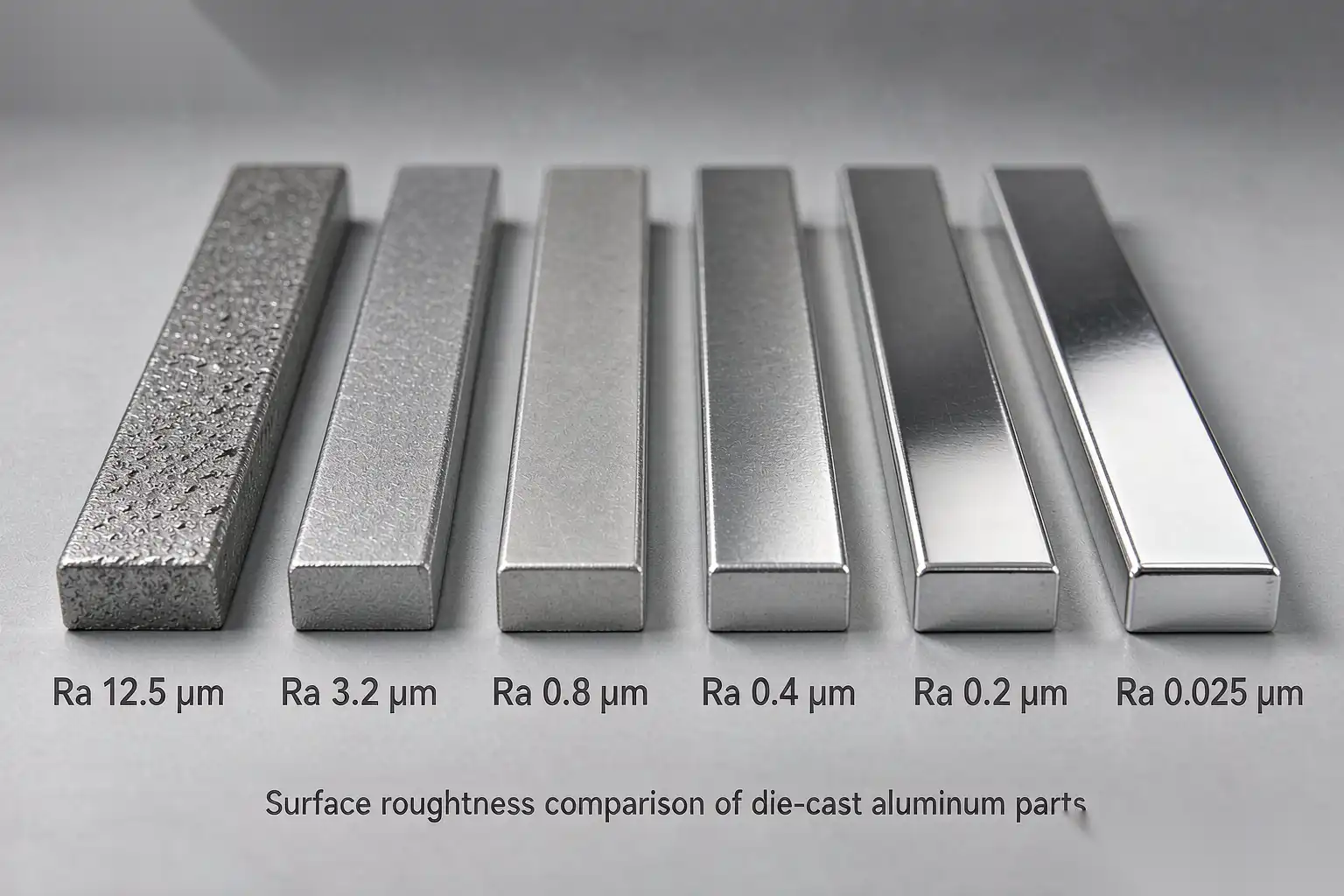
Validation proves the cell meets the spec you wrote in Step 1, not just that it moves. Run at least thirty parts and measure roughness, edge break, and burr removal on each. Therefore, compare the result against your acceptance limit and the quoted cycle time. If quality passes but time fails, raise feed or add a second station. However, never trade finish for speed on a customer-critical surface. Document the validated window before you release the cell.
Add a simple statistical check so drift shows up early, not after a complaint. Plot surface roughness per batch and watch the spread, not just the average. Therefore, set control limits and alert the line when a point escapes. This habit turns validation from a one-time gate into a daily guard. It also gives procurement hard data when you justify the next cell or a second spindle.
Step 11: Train Operators and Plan Maintenance
A robotic grinding cell setup is only as reliable as the people who run it. Train operators to load parts, swap belts, and read fault codes without calling engineering. Therefore, build a short daily checklist for air, dust, and clamp checks. Second, schedule spindle and bearing service by hours, not by failure. For example, replace belts at a set part count to keep finish steady. Good training turns a fragile demo into a dependable production asset.
Step 12: Connect the Cell to Your MES
Connecting the cell closes the loop between the floor and your planning system. Push cycle counts, faults, and OEE to the MES so managers see real output. Therefore, use the robot controller’s open protocol or a small gateway PC. When the data flows, you can spot drift before it becomes scrap. Many plants use this step to fully automate your surface finishing workshop, linking grinding, polishing, and inspection into one line.
Common Robotic Grinding Cell Setup Mistakes
Most failed cells repeat the same avoidable errors, so learn from them before you spend. The list below covers the issues we see most often in the field.
- Undersizing the robot payload and discovering chatter under load.
- Skipping dust collection, which wrecks bearings within months.
- Tuning the whole path at once instead of zone by zone.
- Ignoring fixture repeatability and blaming the robot for drift.
- Forgetting operator training, so a belt change stops production.
ROI SIGNAL — Plants that follow a structured robotic grinding cell setup typically cut grinding labor by sixty percent and lift first-pass yield above ninety-five percent within the first quarter.
Final Checklist Before You Start Production
Before you sign off, walk the cell against the goals from Step 1 one last time. Confirm safety interlocks, dust flow, and fixturing all hold under a full shift. Therefore, re-run the validation batch and check the numbers still pass. Second, make sure the maintenance plan and spare belts are in place. If every item is green, your robotic grinding cell setup is ready to run real parts and earn its keep on the floor.
The approaches described are starting points; an application engineer should tune them to your line.