Die Casting Tooling Maintenance Life: Failure Mechanisms, PM Intervals and True Cost Per Shot
Tooling is the largest non-recurring cost in most die casting programmes and the least well understood. Suppliers quote a tool, buyers amortise it over an assumed shot count, and nobody tracks whether the assumption holds. Two years later the tool is making bad parts and the cost per piece is 40 percent above plan. This article is written for the people who own that number: what shot life is realistic by alloy and complexity, the three mechanisms that actually kill a die, what a maintenance schedule looks like when it is properly run, and how to compute tooling cost per part correctly.
Realistic Shot Life by Alloy and Part Complexity
The numbers below are total shots before major rework or replacement, for tools built in premium H13 class hot work steel, heat treated to 44-48 HRC, run with a competent process. Cheaper steel, poor temperature control or aggressive injection speeds will cut these by half.
| Alloy / process | Simple part, no thin wall | Medium complexity | Structural, thin wall, high integrity | Dominant end-of-life mode |
|---|---|---|---|---|
| Zinc, hot chamber | 800,000-1,200,000 | 500,000-800,000 | Not typical | Gate erosion, parting line wear |
| Magnesium AZ91D | 200,000-300,000 | 150,000-200,000 | 100,000-150,000 | Heat checking, corrosion of cooling lines |
| Aluminium A380 / ADC12 | 150,000-200,000 | 100,000-150,000 | 60,000-100,000 | Heat checking, soldering |
| Aluminium AlSi10MnMg, vacuum structural | 100,000-140,000 | 70,000-100,000 | 50,000-80,000 | Heat checking, gate washout |
| Aluminium with high silicon, over 11 percent Si | 80,000-120,000 | 50,000-80,000 | 40,000-60,000 | Abrasive erosion |
| Copper alloy or brass (mostly gravity) | 30,000-60,000 | 20,000-40,000 | Not typical | Gross heat checking, erosion |
Shot life is not a property of the tool alone. It is a function of four multipliers:
- Casting temperature. Every 30 °C of extra metal temperature reduces die life measurably, because the die surface peak temperature rises with it. Holding aluminium at 660-680 °C instead of 700-720 °C is one of the cheapest life extensions available.
- Cycle time. Short cycles give the die less time to shed heat, so the surface spends more time at high temperature and thermal fatigue accelerates.
- Wall thickness. Thin walls demand higher injection speeds and higher gate velocities, which drive erosion.
- Die temperature control. A die running a stable 200-220 °C surface outlasts one cycling between 120 and 320 °C by a wide margin.
The Three Failure Mechanisms That Kill Dies
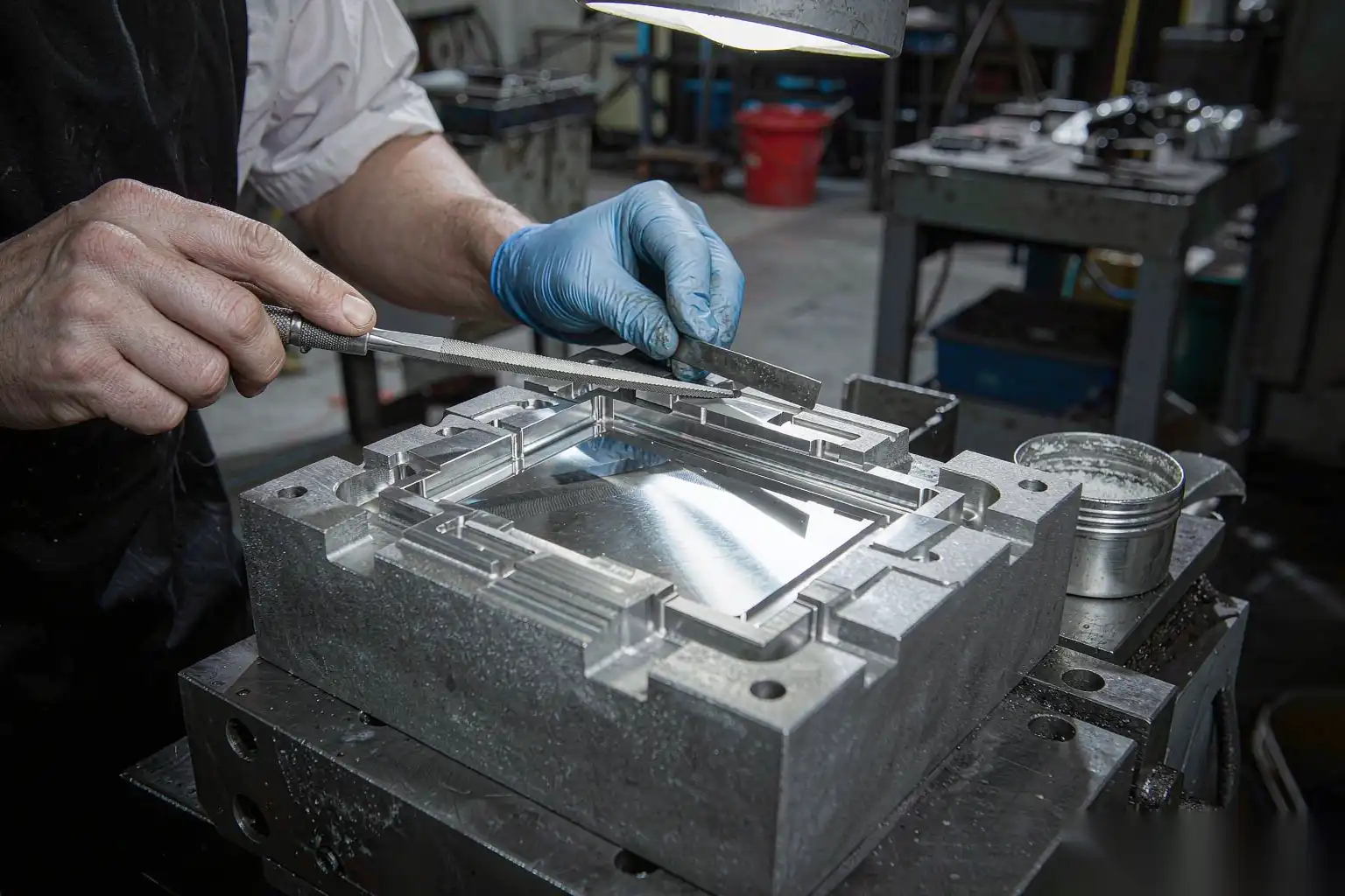
Almost every tool retirement we have investigated traces back to one of three mechanisms, or a combination of them. Recognising which one is active tells you what to change.
Thermal Fatigue and Heat Checking
The die surface sees a full thermal cycle every shot. Metal at 680 °C contacts a surface at 200 °C, driving the first 0.5-1.0 mm to somewhere near 550-600 °C within a fraction of a second, then the surface is quenched by the die spray and conduction into the bulk. The hot surface layer wants to expand but is constrained by the cooler bulk, so it yields in compression. On cooling it goes into residual tension. Repeat that tens of thousands of times and a crack network forms.
What to watch and what to do:
- First visible heat checks on a hard-worked aluminium die typically appear between 5,000 and 20,000 shots, on the hottest areas: gate lands, cores surrounded by thick metal, and the biscuit face.
- A check network is not itself fatal. Cracks of 0.1-0.3 mm depth with openings under 0.05 mm are cosmetic and produce faint lines on the casting surface. They become a problem when they deepen past roughly 0.5 mm or when the crack opening exceeds 0.15 mm and metal starts to penetrate, because penetrated metal is what lifts out and leaves a permanent raised scar.
- Preheating properly matters more than most people think. Going from cold to production in 30-50 shots instead of 8-10 cuts early thermal shock dramatically.
- Die temperature control is the real lever. Keep the surface in a band, not an average. We look for a spread of no more than 40 °C across the cavity face on a production die, measured with a thermal camera at steady state.
- Polishing out early heat checks at 10,000-15,000 shot intervals removes the crack tips before they propagate. This is the highest-return PM task on the list, and it is the one most often skipped.
Erosion and Washout at the Gate
Gate velocity on a conventional aluminium die casting sits between 35 and 60 m/s. At 50 m/s the metal is a high-velocity abrasive jet, and it will remove steel from anything that deflects it. Erosion shows up at the gate land, on the runner walls opposite direction changes, and on any core that sits directly in the metal stream.
- High silicon alloys above 11 percent Si are significantly more abrasive, because primary silicon particles are harder than the die steel surface. Expect 30-40 percent shorter gate life.
- Gate geometry drives the local attack. Reducing gate velocity from 55 to 40 m/s by increasing gate area reduces erosion rate far more than proportionally, roughly with the cube of velocity for impingement erosion.
- Washout produces flash. Progressive flash growth is the visible symptom, and it grows slowly enough that operators compensate with more clamp force until the tool is unusable.
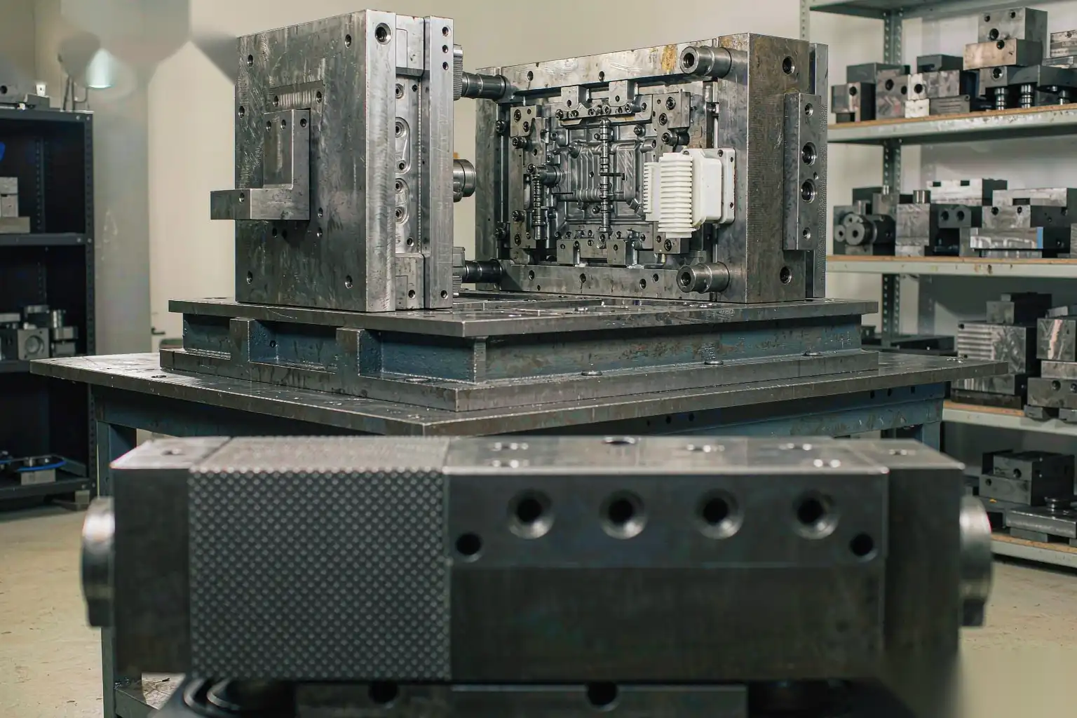
- Repair is by weld build-up and re-machining of the gate, or by replacing a gate insert. Design the tool with replaceable gate inserts where the geometry allows. That single decision converts a 60,000-shot tool into a 150,000-shot tool for the cost of a few hundred dollars per insert set.
Soldering and Corrosion
Soldering is aluminium chemically bonding to the die face, picking up on the casting and leaving steel exposed. It is accelerated by high iron deficiency in the alloy, high die surface temperature, insufficient lubricant, and rough or cracked die surfaces that give the metal something to grip.
- Iron content in the alloy between 0.8 and 1.1 percent is the traditional anti-soldering measure in cold chamber work. Below about 0.6 percent Fe, soldering risk climbs sharply unless the die surface is protected.
- Manganese at 0.4-0.6 percent and controlled Mo or Cr in the steel also help.
- Surface condition matters. A polished, nitrided or PVD coated face resists soldering; a heat-checked, oxidised face invites it.
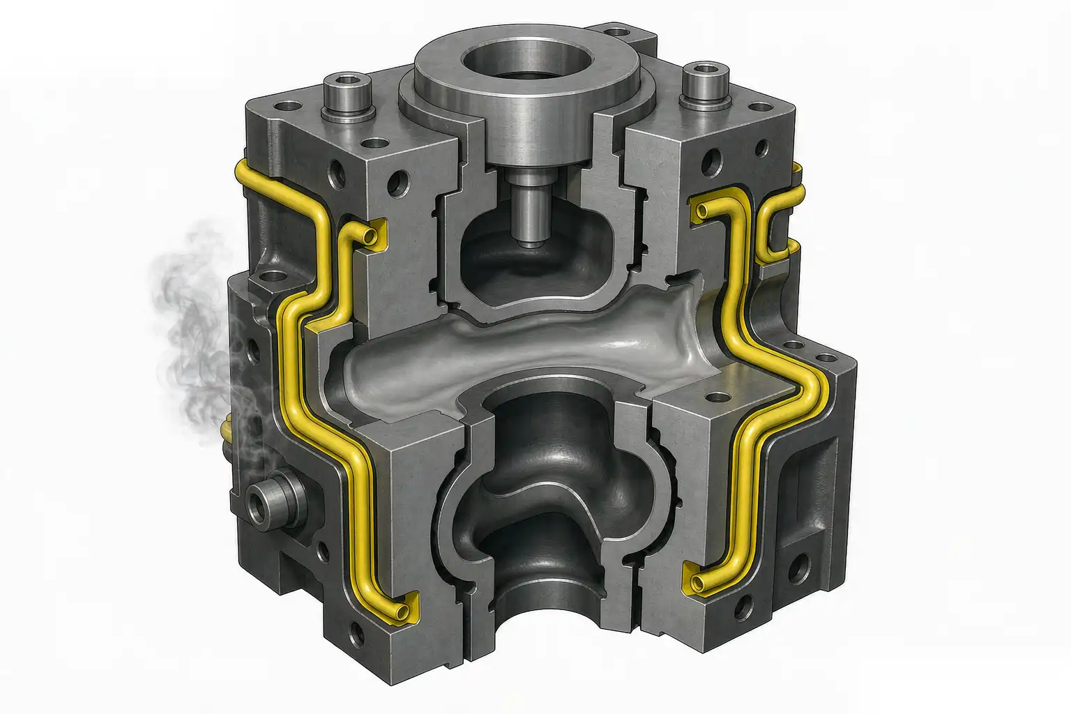
- Water-side corrosion is the other half of this mechanism. Cooling channels rust, scale and, in hard water areas, close up. A channel that has lost 30 percent of its cross-section to scale runs hot locally and the cavity above it heat checks first.
Preventive Maintenance Intervals and PM Checklist
The single biggest predictor of tool life is whether the PM schedule is driven by shot count or by production pressure. Shot count discipline is non-negotiable. The intervals below assume a medium complexity aluminium tool; scale them with the shot life table.
| Interval | Task | Acceptance criterion |
|---|---|---|
| Every shift | Visual check of parting line, ejector return, vent condition | No flash growth, all ejector pins flush within 0.05 mm |
| Every shift | Confirm die temperature and water flow at steady state | Surface within band, outlet water 40-60 °C |
| 5,000 shots | Strip cover half, clean vents and overflows, check slide wear | Vents clear, slide clearance under 0.08 mm |
| 10,000-15,000 shots | Polish early heat checks, re-stone cavity, reapply release coating | No check deeper than 0.3 mm remaining |
| 20,000-30,000 shots | Re-nitride or re-coat cavity surfaces | Case depth 40-80 µm, surface above 900 HV |
| 25,000 shots | Full strip, measure core dimensions, check ejector pin and bushing wear | Cores within 0.05 mm of print |
| 50,000 shots | Dimensional audit of cavity, weld repair decision review | Casting Cpk above 1.33 on critical features |
| 3-6 months | Cooling line descaling and flow verification | Flow within 10 percent of commissioning baseline |
| 6-12 months | Full die stress relief if heavily welded | Per weld repair record |
Additional items that belong on every PM card:
- Record the shot counter reading at every PM event. If the counter is broken, the PM programme is fiction.
- Photograph the cavity face at each full strip, same lighting, same angle. A photo log over 100,000 shots is the best predictive tool you will ever have.
- Track flash thickness on a defined location per PM event. Flash growth from 0.05 mm to 0.25 mm is a quantitative measure of parting line and clamp condition.
- Keep a die history file with every weld repair, its location, filler material and date. Welded areas have different fatigue behaviour and you need to know where they are.
- Verify thermocouple calibration annually. An off-calibration die thermocouple that reads 20 °C low will cook a tool.
Surface Treatments: Nitriding and PVD
Surface treatment is not a life extension guarantee. It is a trade between wear resistance, soldering resistance and thermal fatigue resistance, and the wrong choice makes things worse.
| Treatment | Typical layer | Surface hardness | Best for | Caution |
|---|---|---|---|---|
| Gas nitriding | 80-150 µm, compound layer 5-15 µm | 900-1,100 HV | General aluminium dies, anti-soldering, anti-wear | Compound layer is brittle; remove it from high thermal shock areas |
| Plasma / ion nitriding | 60-120 µm | 900-1,200 HV | Thin cores, complex geometry, better dimensional control | Higher cost, requires good fixturing |
| Nitrocarburising | 30-60 µm | 700-900 HV | Zinc and magnesium dies, lower temperature service | Shallower case, less benefit on hot aluminium work |
| PVD CrN | 2-4 µm | 2,000-2,400 HV | Soldering resistance, gate areas, slides and cores | Thin; if the substrate is soft the coating fails by egg-shell collapse |
| PVD AlTiN | 2-4 µm | 2,800-3,400 HV | Abrasive wear, high silicon alloys | Oxidises above roughly 800 °C; keep substrate hard, 48-52 HRC |
| Duplex, plasma nitriding then PVD | 60-120 µm plus 2-4 µm | Combined | Best available on high-value structural tools | Cost justified only above roughly 80,000 shots expected |
Rules we apply. Nitriding is applied after rough machining and before finish machining and EDM, because the EDM recast layer must be removed before treatment anyway. Re-nitriding is done after every major weld repair and at 20,000-30,000 shot intervals, but there is a limit: repeated nitriding cycles deplete the substrate and the case becomes brittle, so after roughly four to six treatments the tool is at end of life regardless of appearance. PVD is most valuable on cores and slides with poor cooling, not on well-cooled cavity faces.
Cooling Line Maintenance and Descaling
Cooling is the most neglected subsystem on a die cast cell. Water treatment is cheap and scale removal is expensive, but the reverse is what actually gets budgeted.
- Design target: turbulent flow, Reynolds number above 10,000, which in practice means water velocity above 1.5 m/s in the channel. Laminar flow transfers heat several times worse.
- Filtration at 50 µm or finer on the supply, plus a strainer at the return. Swarf and debris in a bubbler or baffle is a common cause of local hot spots.
- Water chemistry: keep hardness low, pH between 7.5 and 9.0, chloride under 100 ppm for stainless components, and use a corrosion inhibitor compatible with the die steel and any copper or brass fittings.
- Scale thickness matters more than people expect. A 0.5 mm layer of calcium carbonate reduces heat transfer by roughly 20-30 percent because the scale conductivity is two orders of magnitude below steel. A die that was tuned at commissioning will drift gradually and the operator compensates by slowing the cycle.
- Descale every 3 to 6 months, more often with hard water. Use inhibited acid circulation or mechanical cleaning; never leave acid in the circuit and always neutralise and flush.
- Verify by flow measurement, not by eyeball. Record litres per minute per circuit at commissioning and compare at every PM. A 20 percent drop is the trigger to descale.
- Check the bubblers and baffles specifically. They are the first thing to block and the hardest to inspect, and losing one silently creates a hot core that heat checks in weeks.
Weld Repair: Decision Criteria and Limits
Weld repair is legitimate and economical when it is controlled, and it is the fastest way to destroy a tool when it is not. The decision criteria we use:
- Repair is acceptable for local heat check removal, isolated erosion at the gate, accidental damage and, in limited cases, modification of non-critical geometry.
- Repair is not acceptable on: sealing surfaces where any micro-porosity in the weld will leak, thin core tips under roughly 6 mm diameter, areas subject to the highest thermal gradient, and any location that has already been welded twice.
- Process discipline: preheat to 350-450 °C for H13, weld with matching or maraging filler, maintain interpass temperature, and post-weld heat treat with a full stress relief. Skipping the post-weld stress relief is what turns a small repair into a crack that runs across the cavity.
- Limit welds per tool. We cap the total welded area at roughly 15-20 percent of the cavity surface and the number of repairs per location at two. Beyond that the remaining fatigue life is unpredictable.
- Every weld must be followed by re-machining, dimensional verification and, where the tool is nitrided, re-treatment of that region.
- Documented reality check: a weld repair typically restores 60-80 percent of the remaining life at that location, not 100 percent. Price the repair accordingly and adjust the remaining shot forecast in the die history file.
Shot-Count Discipline and Spare Insert Strategy
Every PM decision depends on knowing how many shots the tool has run. That sounds obvious and it is routinely ignored.
- Fit a shot counter to the machine and log readings into the die history file at every tool change. Retrofit counters cost very little.
- If a tool runs on more than one machine, do not assume the counts are equal. Have the counters report to a central log.
- Group wears together. Cores, ejector pins, slides, gate inserts and sprue bushings are consumables with their own lifespans, typically 20-50 percent of cavity life, and they should be replaced on a planned basis rather than when they break.
- Spare strategy by part criticality:
| Scenario | Spare strategy | Rationale |
|---|---|---|
| High volume, single cavity, sole-sourced part | Full duplicate tool | Tool failure stops the customer line; cost is amortised over volume |
| High volume, multi cavity | One spare of each high-wear insert set plus a rotatable cavity insert | Keeps capital down while protecting takt time |
| Medium volume, shared platform | Spare insert set for cores, gates and ejectors | Inserts are 5-15 percent of tool cost and cover 70 percent of failures |
| Low volume or prototype | No spares, define repair path instead | Capital is better spent elsewhere |
| Programme with known design change within 12 months | Spare inserts only | Cavity may be obsolete before it wears out |
- Keep the tool maker’s drawings and the steel certification. When a tool fails at 30,000 shots instead of 120,000, the first questions are about steel grade, heat treatment record and hardness, and without certification you cannot answer them.
Computing Tooling Cost Per Part
The calculation is simple and almost always done wrong, because only the purchase price gets amortised. The correct numerator is total cost of ownership over the life of the tool.
Cost per part equals:
- Tool purchase price, plus
- All PM labour and consumables over the life, plus
- Surface treatments, including re-nitriding and PVD recoats, plus
- Weld repairs and re-machining, plus
- Spare inserts consumed, plus
- Scrap attributable to the tool in its end-of-life phase, plus
- Set-up and changeover labour across the life, minus
- Residual or scrap value of the retired tool,
divided by the number of good castings delivered over the life.
Worked example. A structural aluminium tool costs USD 120,000. Over its life it delivers 120,000 shots at 92 percent first-pass yield, so 110,400 good parts. PM labour runs 1.5 h per 5,000-shot event at 24 events, at USD 45 per hour, which is USD 1,620. Re-nitriding every 25,000 shots at USD 1,400 each adds USD 5,600. Weld repairs and re-machining total USD 8,000. Spare insert sets consumed come to USD 6,500. End-of-life scrap attributable to declining tool condition is 1.5 percent of 120,000 shots, 1,800 parts at USD 14 variable cost each, which is USD 25,200, and that is the line everybody forgets. Total is USD 166,920 over 110,400 good parts, or USD 1.51 per part. If you had amortised only the purchase price you would have booked USD 1.09 and under-quoted by 39 percent.
Two consequences worth acting on. First, the end-of-life scrap term is large enough that retiring a tool slightly early, before its scrap rate climbs, is often cheaper than running it to destruction. Plot scrap rate against shot count and look for the knee; on most aluminium tools it sits between 70 and 85 percent of total life. Second, extending life by 30 percent through better temperature control, regular polishing and disciplined descaling has a leveraged effect on cost per part, because it spreads the fixed numerator over more units and avoids the high-scrap tail at the same time.
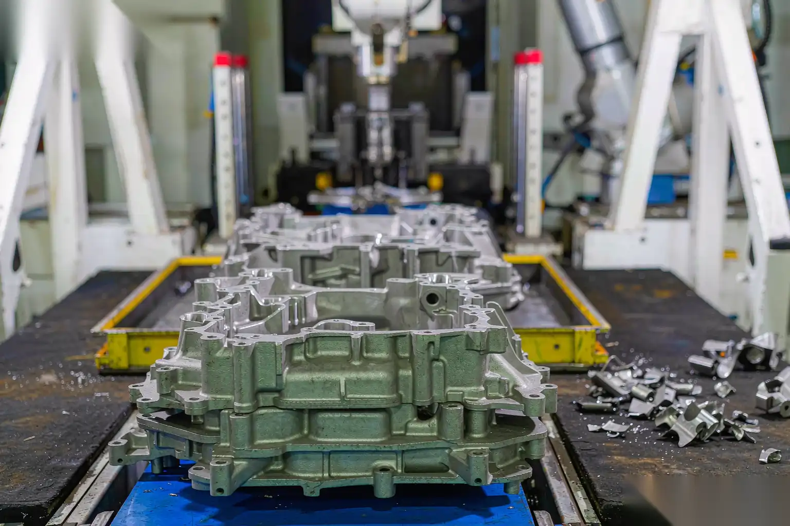
Tool condition also shows up downstream. A tool with growing flash and heat check lines produces castings with heavier parting line burrs and inconsistent gate remnants, which is exactly where automated finishing has to work harder. Our cells with force-controlled floating spindles absorb that variation far better than fixed manual grinding, and the abrasive consumption difference is measurable. For more on the tooling design decisions that drive this, see our aluminum die casting tooling guide, and for the casting quality side of the same problem, aluminum die casting defects and solutions.
DZ Machinery builds robotic deburring and grinding cells with force-controlled spindles that hold consistent edge break even as tooling wears and flash grows. If you are building a die life and cost-per-part model and want the finishing step sized for the end-of-life condition rather than the first 10,000 shots, send us your part drawings and shot volume and we will quote against your real tooling economics.