Die Casting Design for Manufacturability: A Practical DFM Checklist
Die casting is a process where most of the cost and most of the scrap are decided long before the first cavity is cut. The part drawing sets the die geometry, the cycle time, the trimming strategy, and the amount of manual touch-up your operators will have to perform on every single shot. A drawing that looks clean on a CAD screen can force a die that needs four slides, runs at 38 percent fill ratio, and leaves a flash line that takes a person with a file twelve seconds per part to clean. None of that shows up in the quote until it is too late to change it cheaply.
This article is a working DFM checklist for aluminum and zinc die castings, written for the engineer who owns the part drawing and the process engineer who has to make it run. We focus on the decisions that move cost and quality the most: wall thickness, draft, radii, ribs, bosses, datums, flash zones, tolerances, and the feature set that quietly multiplies die complexity. The goal is to make the casting fill well, eject cleanly, and feed straight into a robotic deburring cell without a human standing between the trim press and the finish.
Why DFM starts at the part drawing, not the die
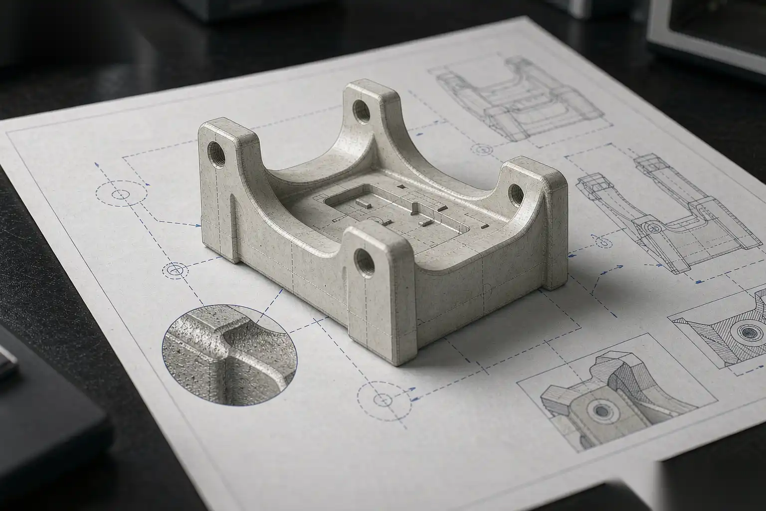
The die is a frozen copy of the part drawing. If the drawing carries a 0.6 mm wall next to a 4.0 mm wall, the die will carry that mismatch, and the process will pay for it in shrinkage and cold laps. Tooling engineers can compensate with local cooling and oversized runners, but compensation has limits and adds cost. The cheapest place to fix a casting problem is the CAD model, at revision zero.
We treat DFM as a three-pass review:
- Pass one: can the metal reach every corner at the chosen gate pressure and freeze before it bridges?
- Pass two: can the part eject without drag, distortion, or a stuck slide?
- Pass three: can the trimmed part be located and deburred by a robot without custom fixtures for every feature?
If a feature fails pass three, it usually also fails pass one or two. Designing for robotic downstream finishing is not a separate step; it is the same logic applied one station later.
Wall-thickness uniformity and alloy minimums
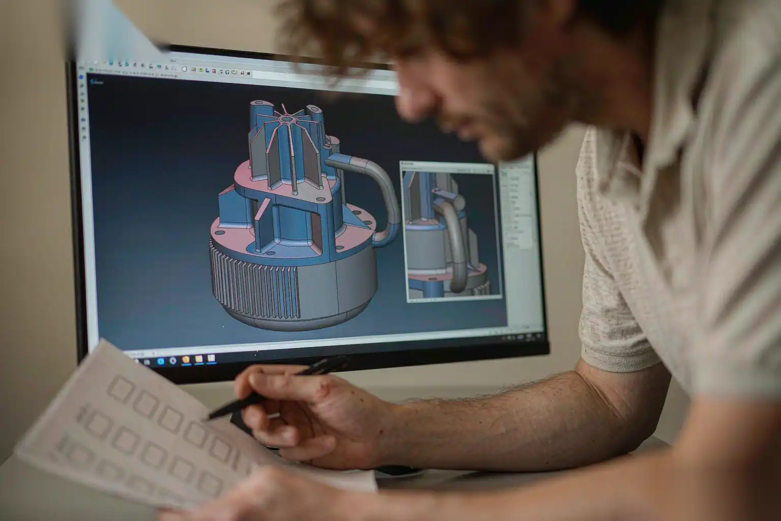
Wall thickness drives everything: fill speed, solidification time, shrinkage porosity, and how much material you pay for per part. The first DFM rule is to keep walls as uniform as the function allows. A good target is a nominal wall with no more than a 2:1 ratio between the thickest and thinnest section on a single part. When a thick section is unavoidable, move the mass into a rib or a locally thickened boss rather than a flat slab.
Minimum wall thickness depends on alloy and part size. These are practical production numbers, not laboratory limits:
| Alloy family | Typical min wall (small part, <100 mm) | Typical min wall (large part, >250 mm) | Practical max wall | Notes |
|---|---|---|---|---|
| Aluminum (A380-class) | 0.8 mm | 1.5 mm | 6.0 mm | Below 0.8 mm, cold laps and short fills rise sharply |
| Aluminum (thin-wall grades) | 0.6 mm | 1.0 mm | 5.0 mm | Needs high injection speed and tight melt control |
| Zinc (Zamak-class) | 0.5 mm | 0.9 mm | 5.0 mm | Flows far; enables thinner walls than Al |
| Magnesium (hot-chamber) | 0.6 mm | 1.0 mm | 5.0 mm | Low viscosity, excellent thin-wall fill |
Uniform walls let the part solidify as a unit. When you must step a wall thickness, use a gradual transition over at least 3:1 length-to-thickness, not a hard step. A hard step is a cold shut waiting to happen, and it is also a place where a deburring brush will catch and gouge.
Our guidance on thin-wall design goes further on transition geometry and fill-speed tradeoffs; see our aluminum die casting thin wall design notes for the calculators we use.
Draft angles by surface and texture
Draft is the taper that lets the part leave the die. Zero draft is a stuck part and a broken core. The required draft scales with surface texture, wall length, and whether the surface is on a moving core.
Practical draft ranges we hold on production tooling:
- External walls, polished die steel: 0.5 degrees minimum, 1.0 degree preferred.
- Internal walls, on fixed cores: 1.0 to 1.5 degrees.
- Internal walls, on moving slides or lifters: 1.5 to 2.0 degrees.
- Textured or shot-blast die surfaces: add 0.5 to 1.0 degree beyond the smooth minimum.
- Deep ribs (depth over 8 mm): 2.0 degrees or more, or the rib walls will drag and peel the coating.
Draft is free on a drawing and expensive to add after the die is cut. If the customer specifies a true vertical wall for sealing, we move that feature to a machined face with a drafted casting wall behind it, then CNC the sealing land flat. That keeps the casting ejectable and gives a real datum for downstream ops.
Radii at parting lines and avoiding hot spots
Sharp internal corners are where heat pools. In a die cavity, a sharp reentrant corner is a hot spot that solidifies last, pulls shrinkage porosity, and becomes a stress concentrator in service. The fix is a radius, and the DFM rule is simple: put a radius on every internal corner, parting line or not.
Recommended practice:
- Internal corners: minimum 0.5 mm radius, 1.0 mm preferred on structural sections.
- Corners at the parting line: radius so the flash strip is continuous and the trim punch has a clean edge to follow.
- Avoid feather edges where a wall meets the parting plane; a 0.3 to 0.5 mm flat or radius prevents a fragile edge that chips in handling.
At the parting line specifically, a planned radius or small flat does two jobs. It sets a known, repeatable flash plane so the trim die cuts a consistent sliver instead of tearing, and it gives the robotic deburring tool a defined edge to ride along. We have seen parts with a ragged parting-line feather take 9 seconds of subjective hand filing per part; a 0.4 mm parting-line radius dropped that to a single pass of a rotating brush.
Ribs versus walls: stiffness without mass
When a part needs more stiffness, the instinct is to thicken the wall. That is usually the wrong move in die casting. A thicker wall solidifies slower, pulls more shrinkage porosity, and adds material weight you pay for twice (metal cost and cycle time). The better route is a rib.
Rib design rules that hold up in production:
- Rib thickness: 50 to 70 percent of the nominal wall it reinforces. A rib thicker than the wall causes a sink on the opposite face.
- Rib height-to-thickness: keep under 5:1 to avoid cooling drag and ejection marks.
- Rib draft: 1.0 to 2.0 degrees per side, same logic as walls.
- Rib spacing: leave room for the trim and deburr tools to reach between them; ribs closer than 6 mm on center can trap a brush.
Ribs also help filling. A thin rib acts as a thermal fin that pulls heat out of an adjacent thick section, which actually improves solidification balance. The drawing should show ribs as deliberate features with their own draft and radii, not as afterthoughts.
Boss design and locating datums
Bosses are the feature that most often gets drawn wrong. A boss that is a solid cylinder of metal as thick as the wall it stands on is a shrinkage risk. The standard correction is to core the boss, make its wall 60 to 80 percent of the main wall, and support it with two or three ribs if it must carry a screw load.
Datum strategy matters more than most drawings show. A casting warps microns to tens of microns across the parting line; if you locate machining and finishing from a soft, featureless face, every part sits slightly differently and your CNC and your robot both chase variation.
We specify datums this way:
- Datum A: a flat machined or trimmed face on the parting-line side, largest stable area.
- Datum B and C: two features or edges on the same side, used to clock the part.
- Never use a draft surface or a slide-generated face as a primary datum.
- Put the locating features where the robotic gripper and the trim nest both can engage them, so one fixture philosophy covers trim, CNC, and deburr.
When the boss is a threaded standoff, leave a machining allowance on its top face and bore it after casting. Hold the cast bore to a generous tolerance and finish it in one CNC operation; this is cheaper and tighter than trying to die-cast a thread-ready hole.
Our tolerances guide covers which features can be held in the die and which must be machined; see aluminum die casting tolerances guide for the feature-by-feature table we quote against.
Designing flash and parting-line zones for robotic deburring
The single biggest contributor to manual labor on a die casting line is unpredictable flash. If the parting line wanders, if flash thickness varies shot to shot, if overflows leave stubs, then no robot can be programmed to a fixed path and expect a clean result. Robotic deburring needs a deterministic edge.
Design choices that make flash robot-friendly:
- Define a single, planar parting line wherever possible. Multiple parting planes multiply flash zones and trim complexity.
- Keep flash thickness in a tight band, 0.05 to 0.15 mm, by controlling lock force and die fit. Thin, consistent flash is cut by a rotating brush; thick, variable flash needs a file or a cutter and a slower cycle.
- Place overflows and vents where their remnants will not land on a cosmetic or sealing surface, and where the trim die can shear them in the same hit as the gate.
- Avoid parting lines that run across a visible Class A surface. Put the line on a hidden edge so post-finish does not have to chase a seam on the customer-facing face.
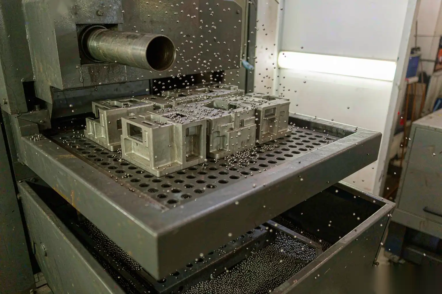
A casting designed this way feeds a DZ robotic deburring cell directly from the trim press. The robot picks a part whose flash plane is known, rides the edge with a compliant floating spindle, and delivers a consistent break with no operator in the loop. Our guide to deburring aluminum die castings with automation walks through the cell layout and the edge-following logic we use.
Tolerance realism by feature
Die casting holds some features tightly and others poorly. Quoting a 0.05 mm tolerance on a slide-generated slot is a way to guarantee scrap. The drawing should match the tolerance to the feature’s process capability.
Rules of thumb we quote against:
- Dimensions fully contained on one die half, no moving cores: plus or minus 0.10 mm per 25 mm is achievable.
- Dimensions that span the parting line: add 0.05 to 0.10 mm because of die parting and clamp variation.
- Slide- and lifter-generated features: looser still, and subject to wear over the tool life.
- Hole-to-hole across the parting line: plan to drill or ream in CNC if it must be tight.
- Flatness and warpage: control by design symmetry and cooling, not by tightening the drawing number.
The practical move is to tolerance the function, not the feature. If a bore only needs to clear a 5 mm shaft, do not call out plus or minus 0.02 mm on a cast hole. Let the casting hold plus or minus 0.15 mm and machine the bore only where the shaft actually seats. Every tolerance you remove from a cast feature is cycle time and scrap you give back to the line.
Features that force slides and lifters (and their cost)
Every undercut, every internal thread, every reverse draft is a moving steel element in the die: a slide, a lifter, a core pull. Moving elements are where die cost, maintenance, and downtime live. They are not forbidden, but they should earn their place.
Cost drivers from side actions:
- A slide adds a cam, a heel, water lines, and a wear plate. Budget a meaningful fraction of the core die cost per slide.
- Each slide is a maintenance point. Slides wear, leak flash, and drift in position; they are the first thing to need service on a high-volume tool.
- Slides slow the cycle. The machine must lock the slide, inject, cool, then retract before eject. That is dead time on every shot.
- Slides generate their own parting line, which is another flash seam the deburr cell must handle.
Design strategies to minimize side actions:
- Redesign an internal undercut as a cored hole plus a pressed-in bushing or a post-cast insert. A guide to insert die casting design covers when an insert beats a slide.
- Replace a reverse-draft snap feature with a draft-tolerant clip that the assembly tolerates.
- If a thread is required, ask whether a cast boss plus a self-tapping screw is acceptable instead of a cast thread that needs a unscrewing core.
- Consolidate multiple undercuts onto one slide direction so one pull serves several features.
When a slide is genuinely required, design its parting line and flash plane with the same care as the main parting line, because the robot will meet that edge too.
A practical DFM checklist
Use this table at drawing release. A “No” on any row should trigger a revision discussion before the die is quoted.
| DFM item | Check | Why it matters | Action if failed |
|---|---|---|---|
| Wall uniformity | Thick:thin ratio under 2:1 | Avoids shrinkage and cold laps | Add ribs, step transition 3:1 |
| Min wall by alloy | Within table above | Prevents short fills | Redesign or change alloy |
| Draft on all walls | 0.5 to 2.0 deg by surface | Enables ejection | Add draft; machine critical faces |
| Radii on internal corners | 0.5 to 1.0 mm min | Kills hot spots and porosity | Add fillets |
| Parting-line flash plane | Single, planar, hidden | Robotic deburr ready | Reroute parting line |
| Rib thickness | 50 to 70 percent of wall | Avoids sink marks | Thin the rib |
| Boss cored and supported | Wall 60 to 80 percent | Avoids shrinkage | Core and rib |
| Datums on stable faces | Not on slides or draft | Holds machining/finish | Redefine A/B/C |
| Tolerances match process | Loosen cast features | Cuts scrap and cost | Tolerance to function |
| Side actions minimized | Fewest slides/lifters | Lowers cost and downtime | Redesign or use insert |
This is the checklist we run internally before any new part enters a DZ cell. It is not exhaustive, but it catches the ninety percent of cost drivers that show up in the first review.
Soft CTA
DZ Machinery builds robotic deburring, grinding, and polishing cells engineered around castings that were designed this way, from trim press to finished part. If you have a part drawing that is about to go to tooling, send it to our engineering team and we will run the same DFM pass before you commit to the die.