Die Casting Cosmetic Flow Line Defects and How Automated Polishing Handles Them
Flow lines are the defect that starts an argument. The casting supplier says the part is within drawing. The plater says the surface is unacceptable. The assembly plant says it can see them from two metres under a showroom light. Nobody is lying — they are each using a different acceptance standard, because no one wrote one down.
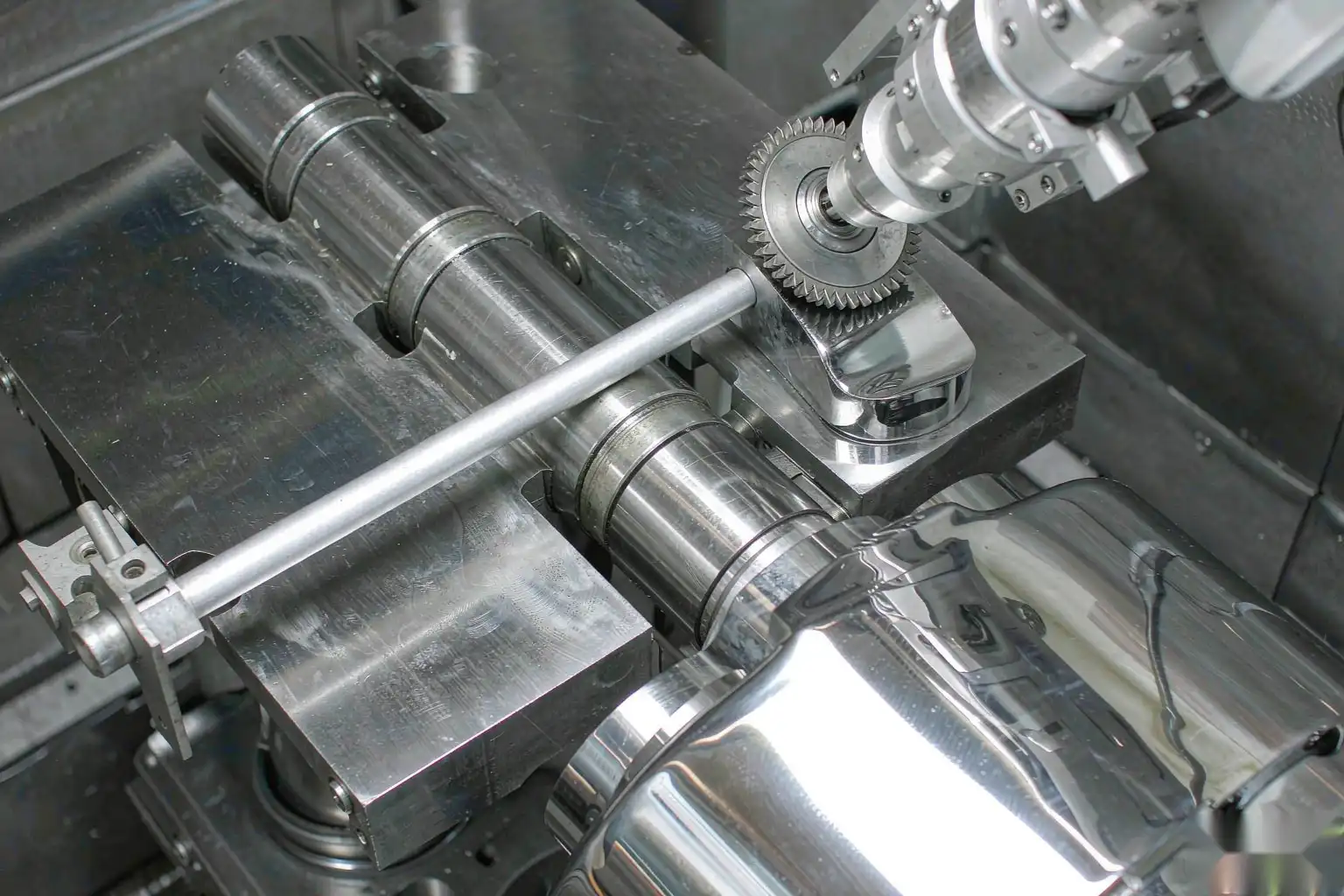
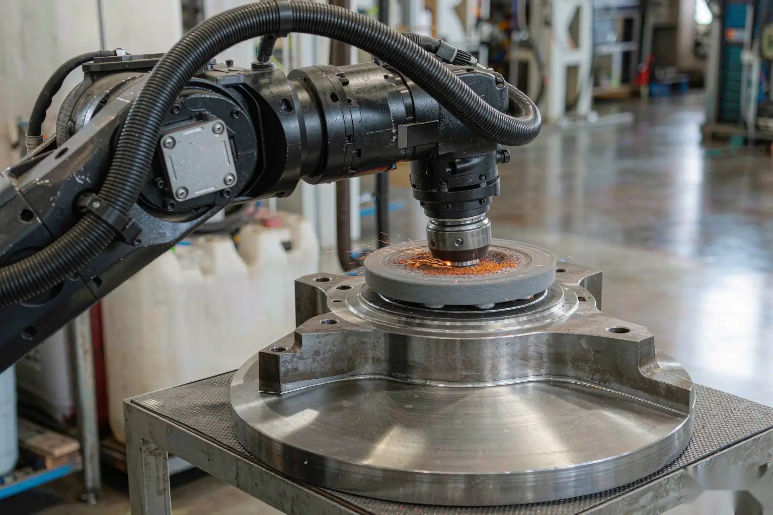
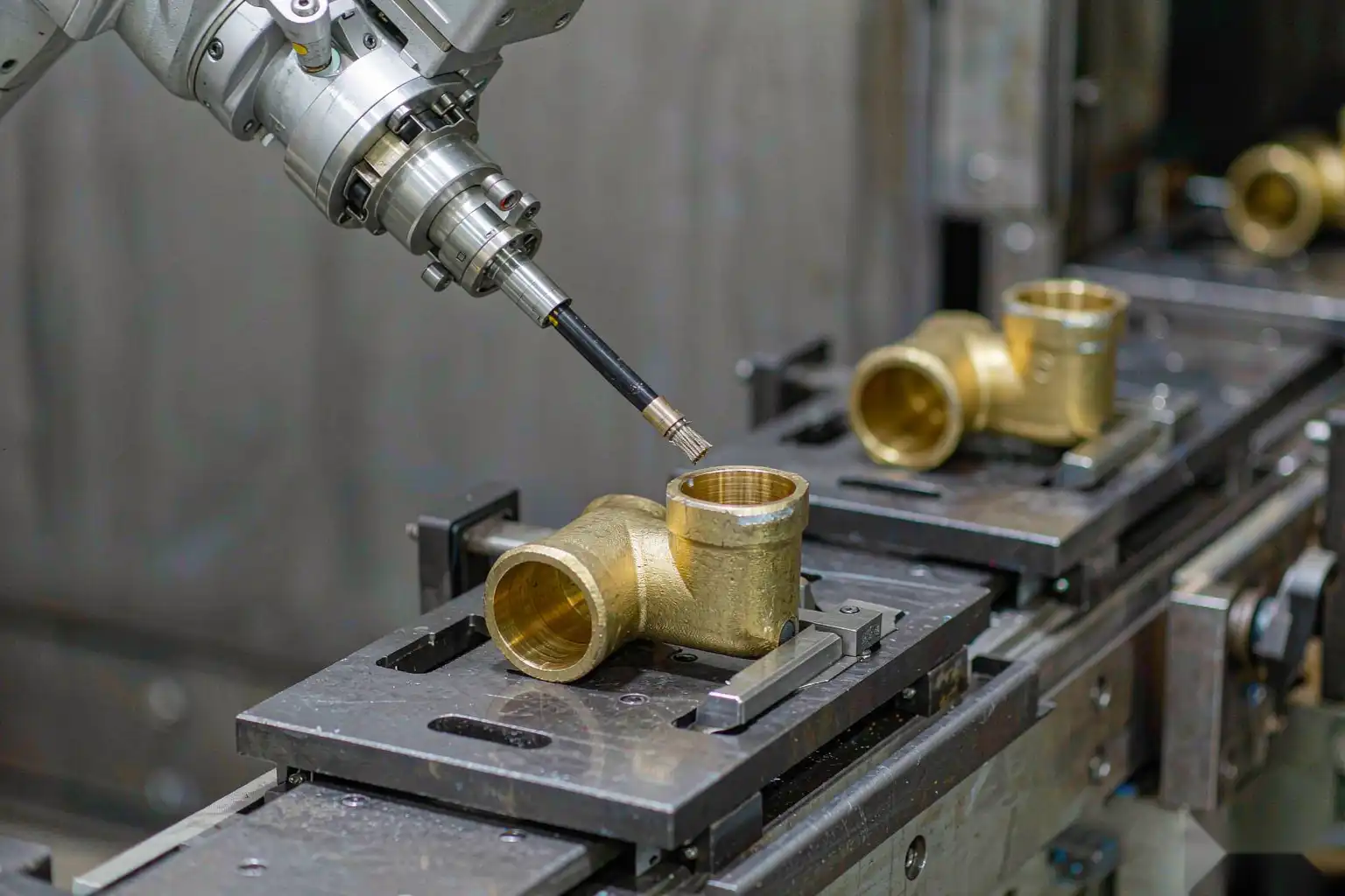
We build robotic grinding and polishing cells for die cast and faucet hardware, so we sit exactly where cosmetic defects become expensive. We see flow lines, swirl marks, cold flow, die sticking transfer, ejector witness and orange peel after plating arrive at the finishing cell every day, and we see which ones a polishing process can absorb and which ones it cannot. This article is that map: root cause, process countermeasure, and what to do when the defect is upstream of the finishing line.
Flow Lines and Swirl Marks
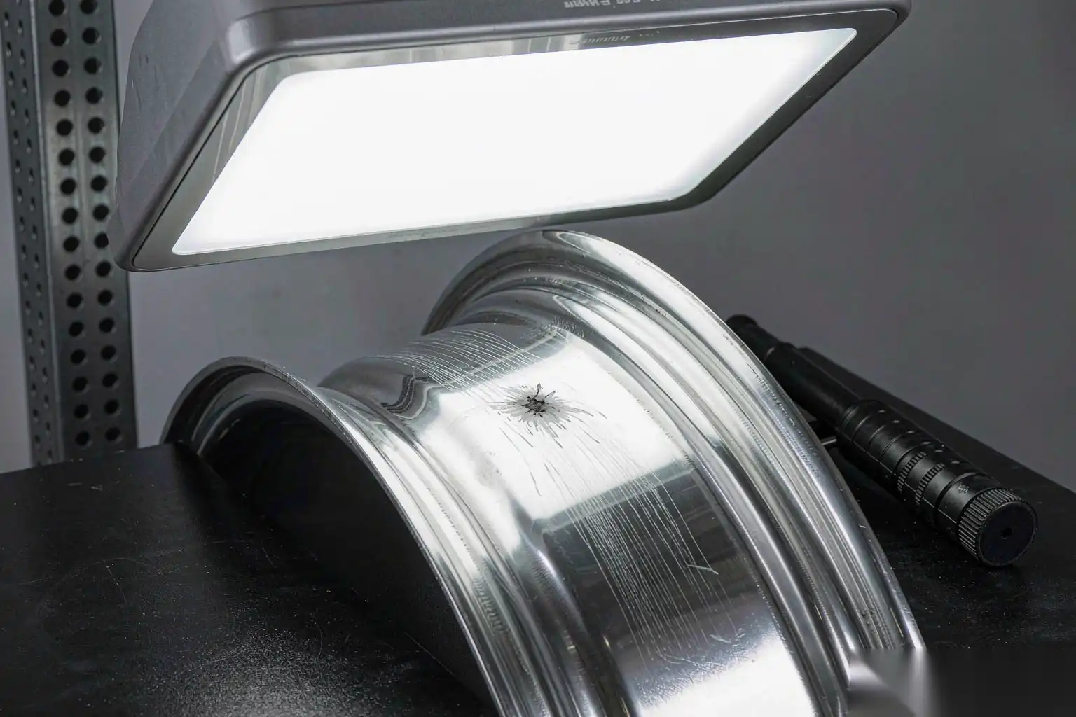
What they look like. Concentric or curved lines on the as-cast surface following the metal flow front, typically 0.1 to 0.5 mm deep, visible as a difference in reflectivity rather than as a step. Under raking light they read as a fingerprint or a wood grain pattern. On a plated part they can disappear under a bright chrome layer or become dramatically more visible, depending on their depth and sharpness.
Root cause. The metal front arrives at the cavity wall, partially solidifies, and is then pushed forward and folded by the following metal. The fold is a surface film of oxide and lubricant, and it is replicated into every subsequent part. The controlling variables:
- Metal temperature at the gate too low, typically below 620 C for ADC12/AlSi9Cu3.
- Die surface temperature too low, below 180 C in the area of the flow front.
- Slow shot velocity too high in the first phase, causing the wave to break and fold.
- Fill time too long for the wall thickness: a 1.5 mm wall filled in 120 ms will show flow lines; the same wall in 40 ms usually will not.
- Too much lubricant, or lubricant that is not being atomised, leaving a liquid film that the metal front rides over.
Process countermeasures, in order of effectiveness:
- Raise die surface temperature in the affected zone to 200 to 240 C. This is the single most effective change, and it usually costs cycle time. A thermal camera on the die face at steady state will tell you the actual number instead of the setpoint on the temperature controller.
- Reduce fill time by increasing the fast shot velocity, so the metal front arrives before it can form a solid skin. Check your PQ2 calculation first; if the gate velocity is already at 55 m/s, the answer is a bigger gate, not more velocity.
- Raise metal temperature to 640 to 670 C at the gate. Watch the trade-off: every 20 C increase costs roughly 8 to 12 percent of die life through increased thermal fatigue.
- Switch to a minimal-quantity spray with better atomisation, and reduce the spray time. If your spray cycle is longer than 2.5 seconds on a 45-second cycle, you are cooling the die more than you are lubricating it.
- Add vacuum. Vacuum does not remove flow lines directly, but it lets you run a slower, less turbulent fill without the porosity penalty, and a smooth plug flow front produces far fewer folds.
Can polishing remove them? Yes, if they are shallow relative to your stock removal budget. A flow line 0.1 mm deep needs roughly 0.15 to 0.2 mm of cut to fully remove, which is achievable with a 120-grit belt pass followed by 180 and 240. A flow line 0.4 mm deep, or one with a sharp oxide fold, needs 0.5 mm or more, and at that point you are changing part geometry, thinning walls and creating a low spot that reads as a wave in reflection after plating. Removing flow lines by polishing is a fix for shallow ones only.
Cold Flow and Cold Shut
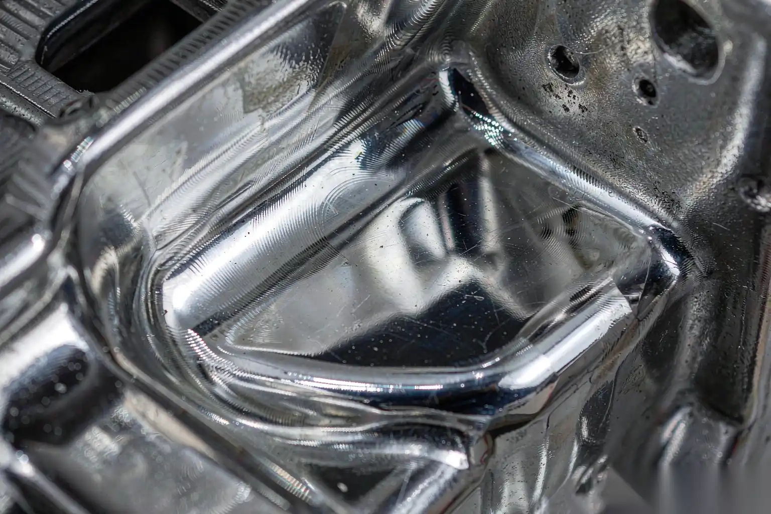
What it looks like. A distinct line, sometimes with a visible step up to 1 mm, where two metal fronts met and did not fuse. Unlike a flow line, a cold shut is a discontinuity, not a surface texture. Under magnification it is a crack-like feature. On a plated part it shows as a dark line that no amount of buffing removes.
Root cause. Two flow fronts meet after both have developed a solid skin, or the metal front stalls against a chill before the cavity is full. The causes are the same family as flow lines but one step further along: lower temperature, longer fill, thinner section, or an obstruction such as a core that splits the flow and forces a rejoin.
Countermeasures:
- Increase gate area or relocate the gate so the flow fronts meet in a non-cosmetic, non-stressed area. This is a tooling change, and it is the only reliable fix.
- Add overflows at the predicted meeting line to carry the cold front out of the cavity.
- Raise metal and die temperature as for flow lines.
- Increase venting at the meeting line; back pressure from trapped air stalls the front and makes it colder.
Can polishing remove it? No. Not reliably. Polishing across a cold shut bridges it with smeared metal and polishing compound, and the line reappears after plating, after anodising, or after the part sees thermal cycling in service. A part with a cold shut on a class A face is a scrap part, and the correct action is to reject it at casting, not at polishing. This is the defect where the distinction between a cosmetic defect and a structural defect matters most: a cold shut on a pressure boundary is a leak path, and polishing it makes it invisible to inspection while making it no less real.
Die Sticking and Heat Check Transfer
What it looks like. Rough patches, drag marks, or a mirror-image crack network transferred onto the part surface, always in the same location, and getting worse through the production run as the die heats up.
Root cause. Two different mechanisms with similar appearance.
- Soldering: aluminum chemically bonds to the die steel where the surface is starved of lubricant, too hot, or where the steel has lost its protective nitride layer. On ejection, material is pulled from the casting surface, leaving a rough patch, and aluminum builds up on the die, which then damages the next part. Deep ribs and thin cores with poor spray coverage are the classic locations.
- Heat check transfer: the die surface has thermally fatigued into a crack network. The cracks are 0.05 to 0.3 mm deep and the casting replicates them in reverse relief. This is a die-life phenomenon, not a process-parameter phenomenon.
Countermeasures:
| Mechanism | Immediate action | Medium term action |
|---|---|---|
| Soldering | Increase spray to the area, add a spot cooler, reduce local die temperature | Improve venting, add a nitrided or PVD-coated insert, review draft angle |
| Heat check transfer | Reduce metal temperature 20 C, reduce peak die temperature, slow the cycle | Dress the cavity, re-nitride, or replace with a premium remelted steel insert |
| Drag from insufficient draft | Increase draft to 1.5 degrees minimum on external walls | Polish the die in the draw direction only, never across |
Can polishing remove it? Soldering damage, yes, if it is shallow and you have the stock. Heat check transfer, partially and at increasing cost as the die ages. This is the defect class where automated polishing earns its keep in a way that is not obvious: because a robot removes a constant amount of material on a fixed path with a fixed force, the depth of heat check transfer that the cell has to remove becomes a measurable, trendable number. You can watch the die degrade from the finishing cell, and schedule die maintenance on data rather than on the complaint of the plating line.
Ejector Pin and Parting Line Witness Marks
What it looks like. Circular or oval marks at the ejector pin locations, either raised or recessed by 0.02 to 0.15 mm, and a linear witness along the parting line.
Root cause.
- Ejector pins set too proud or too deep. The target is flush to 0.05 mm proud, and the pins must be ground as a set after the die is assembled.
- Ejector pins pushing on a cosmetic face. This is a tooling design decision made before the die was cut.
- Insufficient ejection area causing local deformation during ejection while the part is still hot.
- Parting line flash from insufficient clamp force or a worn die face, leaving a ridge after trimming.
Countermeasures:
- Relocate ejection to non-cosmetic areas, or use sleeve ejectors around bosses.
- Grind pins flush as a set, and check the setting every die maintenance.
- Increase clamp force to the calculated requirement plus 15 percent rather than relying on a rule of thumb.
- Control the trim die condition; a worn trim edge produces a burr that the grinding cell then has to remove, which adds cycle time and creates a witness of its own.
Can polishing remove it? Yes, and this is the most common legitimate use of a robotic cell. Ejector pin witness is shallow, deterministic and located in a known place, which is exactly the kind of defect automation handles well: a fixed path, a fixed force, a repeatable result. It is also the defect that manual polishing handles least consistently, because it is precisely the kind of small local variation an operator either over-polishes into a depression or misses entirely.
Orange Peel After Plating
What it looks like. A pebbled, orange-skin texture visible only after plating or anodising, on a surface that looked acceptable as-cast and after polishing.
Root cause. This is a substrate grain problem amplified by the coating. It happens when:
- The casting has a coarse surface grain from slow solidification in a thick section, and the polishing sequence was not fine enough to close it before plating.
- The polishing sequence went from a coarse abrasive to a buff without the intermediate steps, leaving deep scratch lines that the buff smears rather than removes. The smeared layer then outgasses or re-flows in the plating bath.
- The part was over-buffed, generating enough local heat to smear the aluminum surface layer. Aluminum smears readily above roughly 200 C locally, and the smeared layer has a different grain structure and a different plating response.
- There is near-surface porosity. Subsurface pores open up during polishing, and the plating chemistry attacks them. This is the same root cause as the aluminum die casting porosity problem, showing up at the very end of the process chain.
Countermeasures:
- Complete the abrasive sequence. For chrome-plated faucet bodies the typical route is 180, then 240, then 320 grit on the belt, then a sisal or cut-and-colour stage, then a loose cotton buff with the appropriate compound. Skipping 320 and going 240 to buff is the most common cause of orange peel we encounter.
- Control buffing pressure and dwell. On a force-controlled spindle, 30 to 60 N with a dwell under 1.5 seconds per zone is a reasonable starting window for zinc and aluminum hardware; on a manual wheel, operators routinely exceed 150 N without noticing.
- Verify the incoming casting surface. Measure Ra before polishing. If the as-cast Ra is above roughly 3.2 µm on a class A face, no polishing sequence will produce a plating-grade finish economically, and the fix belongs in casting.
- Check for near-surface porosity on a sample before you commit the batch. A 10-minute section and polish under a microscope at 50x will save a plating rack of scrap.
Specifying Cosmetic Class With Limit Samples Rather Than Adjectives
Almost every cosmetic dispute we get pulled into has the same origin: the specification said “no visible defects” or “cosmetically acceptable.” Those words mean different things to a caster, a polisher and a plater.
A workable cosmetic specification has five elements:
- Zones. Class A, B and C areas marked on the drawing or on a shaded 3D view. Class A is what the end user sees at arm’s length; class B is visible during handling or installation; class C is never seen. On a faucet body, the entire visible exterior is class A; the underside that meets the basin is class C.
- Viewing conditions. Distance, time, and light. A realistic standard for class A: 500 mm viewing distance, 5 seconds per face, 800 to 1,000 lux diffuse white light, viewed without magnification at normal reading angle. Write this down, because it is the difference between a 2 percent and a 20 percent rejection rate.
- Limit samples. Physical parts, sealed, dated, signed by both parties, held at both locations, and replaced on a defined cycle. Limit samples beat written descriptions because they do not require interpretation. For flow lines specifically, the useful limit sample is a part with the worst acceptable flow line, not a perfect part.
- Quantified acceptance. Where you can, use numbers: flow lines no longer than 8 mm and no deeper than 0.10 mm on class A; no parting line step above 0.05 mm; no ejector witness visible from 500 mm. Where you cannot, say “match limit sample.”
- Measurement method. Ra or Rz with the cut-off length and the number of readings, and the direction of measurement. Ra 0.4 µm on a curved faucet shoulder measured across the lay is a different requirement from the same number measured along it.
The die casting surface finish standards article on our site goes through the roughness and limit sample framework in more detail, and it is worth aligning your RFQ and your inspection plan to the same numbers.
Why Manual Polishing Hides the Problem and Automated Polishing Exposes It
This is the point most people resist, and it is the most valuable one.
A skilled manual polisher is a feedback controller with very high bandwidth. When a part arrives with a slightly deeper flow line, the polisher presses a little harder and dwells a little longer, and the part comes out acceptable. When the casting drifts over a shift as the die heats, the polisher compensates continuously and invisibly. The output looks consistent because the input variation has been absorbed by human adaptation.
That is genuinely useful in the short term. It is also why the underlying problem never gets fixed:
- No one measures the incoming variation, because the finished output never varies.
- The die degrades further, because nothing signals that it is happening.
- Capacity is unstable, because the compensation time is not in the standard cycle time — on a bad day, cycle time per part is 30 percent higher and nobody can say why.
- The process cannot be transferred. It lives in the hands of two people, and when one of them leaves, cosmetic yield drops and no one can explain it.
A robotic cell with a force-controlled floating spindle works the other way round. The path is fixed, the force is set, the abrasive sequence is programmed, and the cycle time is the same on every part. If the incoming casting has a flow line 0.3 mm deep instead of 0.1 mm, the robot removes the same amount of material and the defect remains. The cell does not hide the variation; it reports it.
That is exactly what you want, for three reasons. First, it gives you a signal to act on upstream — the defect count from the finishing cell becomes a die maintenance trigger. Second, it makes the cosmetic result reproducible, which is what a class A requirement actually means. Third, it makes the process auditable and transferable, which is what your customer’s auditor will ask for.
The transition is uncomfortable. When a plant moves from manual to robotic polishing on a cosmetic part, cosmetic rejects usually go up for two to four weeks. That is not the robot being worse; it is the existing casting process being exposed. The plants that get through it are the ones that use the exposure: they take the defect map from the cell back to casting, fix the die temperature and the spray, and come out the other side with a genuinely capable process instead of an invisible subsidy from the polishing department.
DZ Machinery builds robotic grinding and polishing cells for die cast and faucet hardware with force-controlled floating spindles, automatic abrasive and compound management, and multi-station rotary or inline layouts for zinc handles, faucet bodies and lock plates. If you are fighting flow lines or an inconsistent cosmetic result on a plated part, send us the part drawings, your current abrasive sequence and a limit sample if you have one, and our engineering team will run the parts on a cell and give you the defect map and a process window back.