CMM Dimensional Inspection for Die Castings: Strategy and Traps
Why die castings break conventional CMM habits
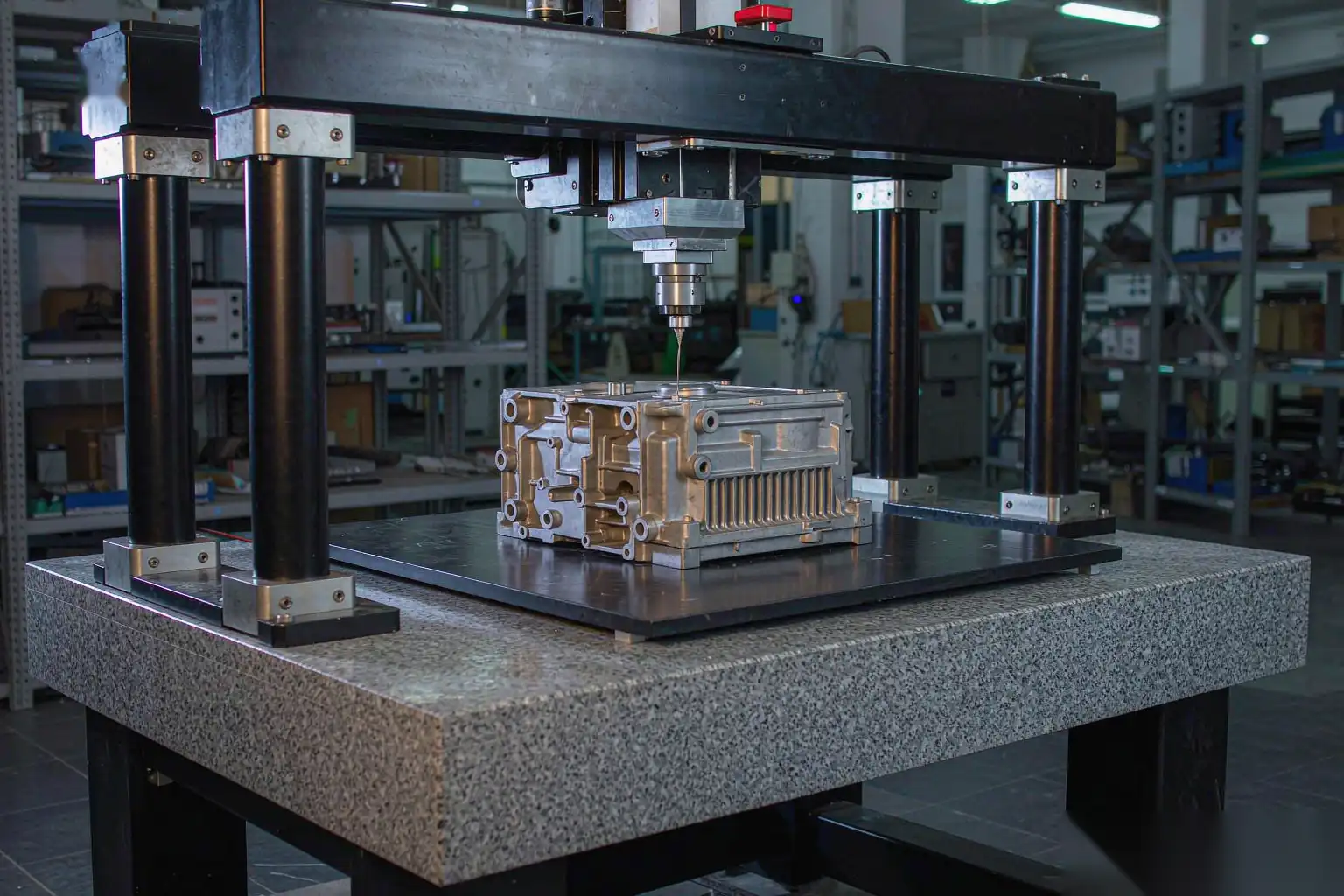
Most coordinate measuring machine (CMM) routines are written by people who learned metrology on machined parts. A machined part is created by removing material from a known reference, so its datum surfaces are flat, true, and repeatable to a few microns. A die casting is the opposite. It is formed by injecting molten aluminum into a steel cavity, it cools under constraint, it warps as it solidifies, it carries draft on every vertical face, and it leaves the die with a parting line and gate remnant that no machining operation will necessarily remove. When you put that part on a CMM and measure it the way you would measure a milled bracket, you get numbers that are mathematically correct and practically meaningless.
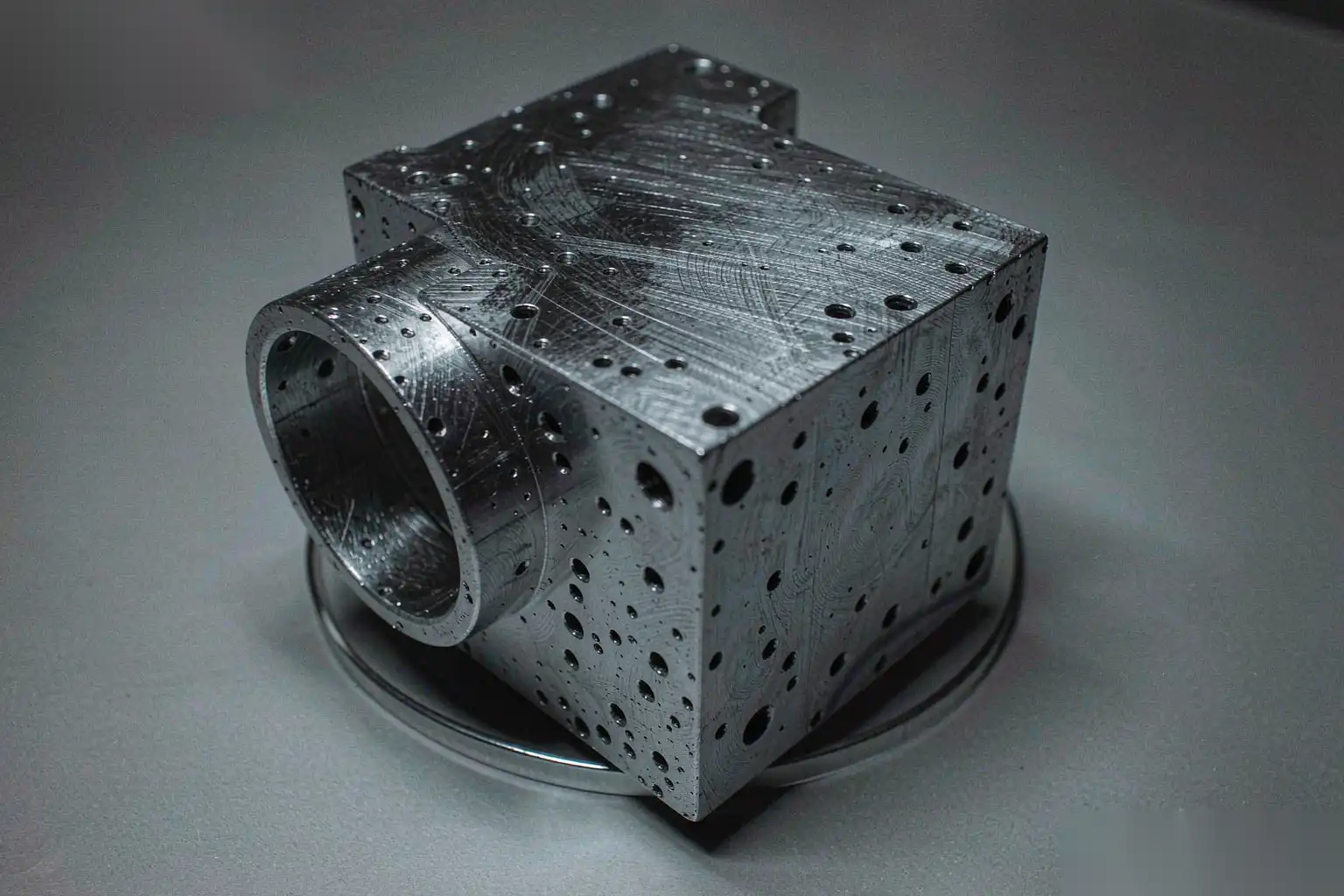
The core problem is that the surfaces you are forced to measure on a die casting are frequently the as-cast, die-formed surfaces, not machined reference planes. Those surfaces are not planes in the geometric sense. A drafted side wall is a truncated cone. A large flat face has sink marks, ejection push, and micro-level warpage. A boss may be pulled slightly out of round by shrinkage. If your datum, or your measured feature, or both, sit on these surfaces, every downstream number carries that error folded into it.
This article walks through the datum strategy, feature selection, warpage traps, probe choices, and uncertainty math that govern useful CMM inspection of die castings, and closes with how to feed the data back into trimming and robotic grinding so the measurement actually earns its cost.
Datum strategy on cast versus machined surfaces
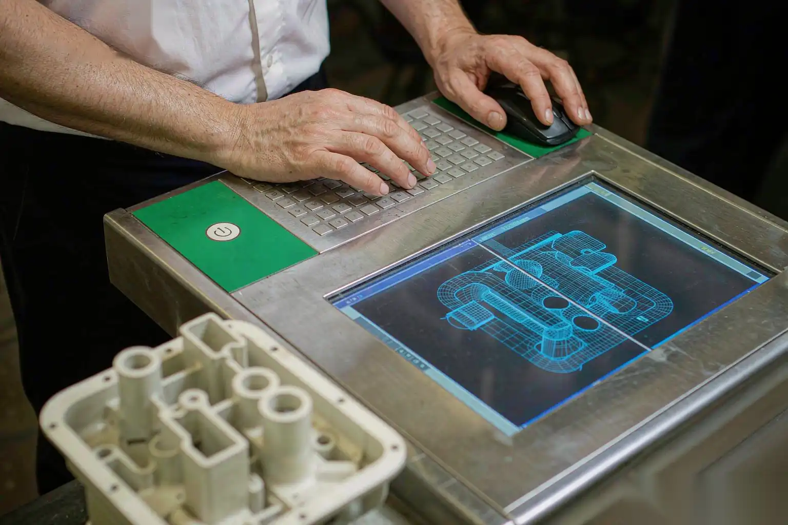
The single most common mistake we see in die casting inspection plans is the selection of datums from cosmetic as-cast surfaces that happen to be convenient. A datum is supposed to be a theoretically exact reference. A cast surface with 1.5 degrees of draft and 0.1 mm of local sink is not theoretically exact; it is a statistical approximation of a plane.
When the part has machined surfaces, use them as the primary datums. A face that has been fly-cut or milled to a flatness of 0.02 mm is a legitimate A datum. A bored or reamed hole is a legitimate B or C axis datum. Machined datums are true by construction and they remove most of the ambiguity. The tolerance guide at aluminum die casting tolerances guide shows which features should be machined to reach IT7 to IT8 and which can stay as-cast at IT9 to IT13.
When there are no machined surfaces, you must define the datum on the cast surface deliberately:
- Pick the datum face as the surface that contacts the customer’s assembly fixture, not the surface that is easy to touch. The part should be measured the way it is used.
- If the primary datum is a large cast face with draft, recognize that “flatness” measured on it is the flatness of a cone cross-section, not a true plane. Report it as profile or as a constrained fit rather than a naive flatness callout.
- For a functional mounting boss used as a datum, measure its axis from the actual cast diameter, not from a nominal CAD circle. Shrinkage can move the mean diameter by 0.05 to 0.15 mm on a 30 mm boss.
- Where the part seats on three points in assembly, simulate that three-point seat on the CMM with a nest or fixture, and build the datum reference frame from the functional locators. This is far more representative than a free-state 3-2-1 alignment on a warped part.
- Avoid using the parting line or the gate stub as any datum. These are the least repeatable regions of the casting.
A constrained least-squares best-fit has its place, but use it with care. Best-fit can hide a real problem by distributing error across the whole part so that no single feature looks bad. We reserve best-fit for first-article characterization and for understanding process variation, not for production pass-fail decisions where a rigid datum reference frame is the honest test.
Feature selection that actually matters
A typical die casting drawing lists 150 to 250 dimensions. Measuring all of them on a CMM is a waste of cycle time and, worse, it buries the few numbers that matter under a cloud of noise. The useful approach is to reduce the inspection plan to the critical-to-function (CTF) features.
A practical method:
- List every feature that determines fit, seal, or function in the customer’s assembly. For a valve body that is the bore true position, the flange face flatness, the thread axis, and two locating pins. For a housing it is the mounting plane, the connector boss axis, and the seal groove diameter.
- Express those features in GD&T rather than stacked coordinate tolerances. A true position callout of 0.10 mm MMC on a bore tells you more about assemblability than twelve separate ±0.05 mm coordinate dimensions.
- Demote everything else to reference dimensions. Measure them once at first article and then only spot-check if a trend appears.
- Build the control plan so that first-article inspection (FAI) is full, but in-process SPC runs only on the CTF features. This typically cuts CMM cycle time by 60 to 70 percent while improving defect detection on the features that cause returns.
A useful rule of thumb from our cell data: roughly 80 percent of field fit complaints trace back to five or fewer features on the part. If your inspection plan is not weighting those five features heavily, you are spending metrology budget in the wrong place. The machining allowance and datum discussion at die casting machining allowance datum explains how to decide which features must be machined to hold and therefore which ones deserve the tightest CMM scrutiny.
Warpage versus true position traps
Warpage is the silent failure mode of die casting metrology. A part ejected from the die at 300 C to 400 C continues to move as it cools, as residual stress relaxes, and again after trimming and any heat treatment. The whole part distorts, so the relationship between your datum and your measured feature is not fixed.
The trap works like this. You measure a bore against a datum reference frame built on a warped cast face. The bore is correctly located relative to the way the part actually sits in the customer’s fixture, but because your CMM datum carried 0.15 mm of warp, the true position number comes back at 0.18 mm against a 0.15 mm tolerance and the part is rejected. It was never out of spec in assembly. Conversely, a part can pass the CMM because your soft datum conformed to the part, while the real mounting interface would have shown a gap.
To separate these cases, distinguish the geometric element types:
- Form error: flatness, straightness, roundness of a single feature in isolation.
- Orientation error: perpendicularity, parallelism, angularity relative to a datum.
- Location error: true position, concentricity relative to the datum reference frame.
These compound. A warped datum injects form and orientation error directly into every location number computed from it. If you report a true position value without stating the datum form error, you are reporting a number whose largest contributor may be the datum itself.
Practical controls we use:
- Measure the datum plane’s flatness first and record it next to every TP result so the reader sees how much warp is in the frame.
- For flatness-critical parts such as pump flanges and telecom housings, control warpage at the source rather than trying to measure around it. The warpage and flatness guidance at die cast warpage flatness control covers die cooling balance, ejection timing, and stress-relief steps.
- Allow a stabilization hold. Aluminum parts that are measured immediately after trim can move 0.02 to 0.08 mm over the next 24 hours as stress relaxes. We measure after a defined stabilize period, normally 16 to 24 hours at ambient, for first-article and periodic re-checks.
- When a borderline TP result appears, re-reference the part to its functional locators rather than the free-state datum before scrapping it.
Probe selection for soft aluminum
Aluminum is soft. A380 sits around 80 to 100 HB, A356 around 70 to 90 HB, and zinc alloys are softer still. A CMM probe that is fine on steel will dent, scratch, or smear an aluminum surface, biasing the reading and in some cases damaging a sealing face.
Key decisions:
- Trigger probes versus scanning probes. A scanning probe collects a dense point cloud useful for profile and form, but it applies contact force continuously along the path. On thin walls the accumulated lateral force can deflect the part and corrupt the scan. A touch-trigger probe with a low contact force is often safer for soft alloys.
- Reduce stylus force. Most CMM controllers let you set approach, measuring, and retract force. For aluminum we run the lowest force that still gives a repeatable trigger, typically a few tenths of a newton, and we add a slow final approach speed near the surface.
- Tip geometry. A 3 mm ruby ball is the standard general-purpose tip. For small bores under 6 mm diameter, drop to a 1 or 2 mm tip but accept slower cycles and tighter tip-length calibration. A disk or radial probe helps reach internal grooves a ball cannot.
- Support thin features. A wall measured while cantilevered will spring under the probe. Fixture the part against a backstop at the measurement region so the reading reflects geometry, not deflection.
- Temperature discipline. Aluminum’s coefficient of thermal expansion is about 23 micrometers per meter per degree C. A part 200 mm long measured 5 C above the 20 C reference grows 0.023 mm/m times 0.2 m times 5 C, or about 0.023 mm. That is a third of a typical ±0.05 mm tolerance. We let parts equilibrate to the metrology room temperature, normally 20 C plus or minus 1 C, for at least two hours before critical measurement.
- Calibrate the probe ball diameter and effective length at the start of every shift. A 2 micron error in ball diameter propagates into every point.
Non-contact sensors such as laser line scanners or optical probes avoid surface damage entirely, but they struggle with the high reflectivity and draft of as-cast aluminum and they cannot see into shadowed features. We use them for delicate reference surfaces and reserve contact probing for CTF features.
How measurement uncertainty eats your tolerance
A CMM number is not the truth. It is an estimate with a confidence interval. The moment you forget that, you start scrapping good parts and shipping bad ones.
The uncertainty budget for a die casting measurement combines:
- The CMM machine error, often stated as MPE (maximum permissible error), for example 1.8 plus L/300 micrometers where L is in millimeters.
- Probe calibration uncertainty from the ball and tip-length calibration.
- Temperature uncertainty from part and room deviation from 20 C.
- Fixturing and alignment uncertainty, dominated by how well the datum was established.
- Operator and program repeatability, captured by repeated measurement of a witness part.
- Datum definition uncertainty, which on a warped cast surface can be the largest single term.
Combine these by root-sum-square to get a standard uncertainty, then multiply by a coverage factor k (usually 2) for an expanded uncertainty U at about 95 percent confidence.
Work the arithmetic. Suppose a bore true position tolerance is 0.15 mm. If your expanded uncertainty U is 0.06 mm, then the true value could be 0.06 mm away from your reading in either direction. Your real safe window for declaring a pass is not ±0.15 mm but ±0.09 mm. A reading of 0.13 mm is reported as pass, but the true value could be 0.19 mm, a genuine reject. A reading of 0.10 mm is reported as pass, but it could be 0.16 mm, also a reject. Roughly a fifth of your borderline pass decisions are wrong.
The accepted rule is that measurement uncertainty should be no more than one-tenth of the tolerance for a capable process, or at worst one-quarter. If U is 30 to 40 percent of the tolerance, you cannot make an honest pass-fail call and you must apply a guard band: accept only when the measured deviation is less than T minus U (or T minus 0.4U for lower risk), and reject only when it exceeds T plus U. The band between is inconclusive and triggers re-measurement or a better gauge.
This is why a low-cost CMM reading quoted to three decimal places on a tight as-cast tolerance is dangerous. The decimals imply precision the budget does not support. Document the uncertainty, state the guard band, and report the datum form error alongside the location number. A number without its uncertainty is a rumor.
Feeding results back to trimming and grinding
A CMM is an expense until its data changes the process. The goal is a closed loop: measure, trend, adjust, verify.
Concrete feedback paths we use in DZ finishing cells:
- Trim-induced shift. If dimensional drift concentrates near the gate or parting line, the trim die or the deburring sequence is loading the part asymmetrically. Adjust trim support or the robot’s trim path and re-measure the affected CTF feature.
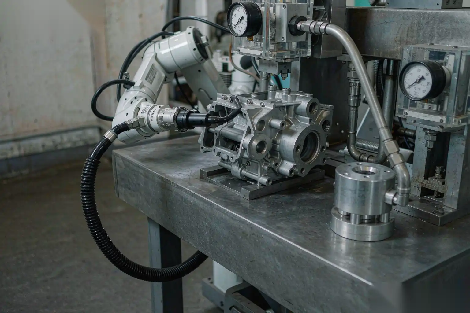
- Robotic grinding over-removal. When a bore-adjacent seal face measures consistently low after grinding, the force-controlled spindle is removing too much stock. Feed the CMM offset back into the robot path so the next parts hold the target. Our force-control spindles accept a per-feature offset directly from the measurement file.
- SPC triggers. When Cpk on a CTF feature drops below 1.33, the cause is usually die wear, plunger tip wear, or thermal drift rather than the casting process alone. The CMM trend tells you which cavity and which dimension, pointing maintenance at the right insert.
- Die maintenance scheduling. Track bore diameter and flatness by cavity number. When a cavity trends toward the edge of the band, rotate or refurbish that insert before it produces out-of-spec parts.
The machining allowance and datum reference at die casting machining allowance datum is the engineering basis for deciding how much stock the grinding cell is allowed to remove and where the final datum must be re-established after machining. The tolerance capabilities laid out in aluminum die casting tolerances guide set the realistic CTF targets the CMM checks against.
Building a tolerance strategy that the process can hold
The last trap is specifying tolerances the die casting process cannot meet, then fighting the CMM data forever. As-cast features follow natural process capability. A bores and faces left as-cast typically hold IT9 to IT13 depending on size and section; a 50 mm as-cast dimension might be controllable to about ±0.10 to ±0.20 mm, not ±0.02 mm. If a function needs ±0.02 mm, machine the feature. Reserve the tight tolerance for the machined operation and let the CMM verify the machined result, not the impossible as-cast one.
A simple decision table helps the design review:
| Feature type | Typical as-cast grade | Machined grade | CMM strategy |
|---|---|---|---|
| Large flat mounting face | IT11 to IT13 | IT7 to IT8 | Measure flatness after machining |
| Bore under 20 mm | IT10 to IT12 | IT7 to IT8 | Machine, then TP vs datum |
| Thread boss axis | IT11 | IT8 (ream) | Datums on machined seat |
| Cosmetic draft face | not graded | n/a | Reference only, no CTF |
| Seal groove diameter | IT10 | IT8 to IT9 | Machined, profile check |
Match the datum, the probe, the uncertainty budget, and the tolerance to the feature, and the CMM becomes a tool that tells you the truth instead of a source of arguments about numbers nobody trusts.
DZ Machinery builds robotic deburring, grinding, and polishing cells that close this loop for die casting lines, ingesting CMM offsets to auto-correct robot paths and holding the CTF features your assemblies actually depend on. Talk to our engineering team about your part drawings and we will size the inspection and finishing sequence together.