Die Cast Warpage and Flatness Control: Capability, Causes, and Countermeasures
Warpage is the defect that turns a good casting program into a permanent argument. Unlike porosity, it is visible. Unlike flash, it cannot be trimmed away. And unlike most casting defects, it frequently appears after the part has already passed inspection, because the stress that causes it is released by the next operation — a machining cut, a heat treatment, or simply a night on the floor.
For automated finishing, warpage is the single most damaging casting defect. A grinding or polishing robot programmed on a nominal part and presented with a part that is 1.5 mm out of flat will either cut too deep in the high spots and miss the low spots entirely, or crash the spindle. Compliance helps, but it has a working range, and beyond that range no control strategy saves you.
This article sets out why die castings warp, realistic flatness capability by part size, the design rules that prevent it, process countermeasures, straightening options, measurement method, and the interaction with automated finishing.
What Warpage Actually Is
Warpage is a shape error caused by non-uniform strain. The casting leaves the die at a shape, and the strain field inside it is not in equilibrium; when part of the constraint is removed, the shape changes until it is. Three categories help in diagnosis:
- Global bow. The whole part curves along its long axis. Usually driven by a through-thickness thermal gradient or by differential contraction between a thick and a thin region.
- Local distortion. A specific feature — a flange, a rim, a boss pad — deviates from nominal while the rest of the part is fine. Usually driven by local cooling imbalance or by ejection.
- Time-dependent movement. The part measures in tolerance at inspection and out of tolerance 24 hours later. Driven by residual stress relaxation, natural ageing, or continued precipitation in the alloy.
Distinguishing them matters because the countermeasures differ. Global bow is a thermal and design problem. Local distortion is usually a die cooling or ejection problem. Time-dependent movement is a stress relief problem, and no die change will fix it.
The Five Mechanisms
Thermal gradient through the section
The two faces of a casting do not cool at the same rate. The face against the die surface loses heat fast; a cored or deeply pocketed face loses it slowly. If one face contracts before the other has finished contracting, the part bends toward the hotter side as it cools. The magnitude scales with the square of the section thickness difference and with the cooling rate difference. This is why a 3 mm wall next to a 10 mm boss is the classic warp geometry, and why uniform wall thickness is the first design rule.
Ejection stress
Ejector pins push on a casting that is still hot, typically at 350 to 450 °C for aluminium, and still well below its yield strength. If the pins are unbalanced in number, diameter or stroke, or if a core is dragging, the part is bent as it leaves the die and it stays bent. Symptoms are diagnostic: bow away from the ejector side, a consistent direction on every shot, and often visible ejector pin indentation depth variation around the part. This is usually the first thing to check, because it is the cheapest to fix.
Uneven section and differential contraction
Even with uniform die temperature, a casting with a thick rim and a thin web contracts differently in different regions. The thin web freezes first and becomes rigid; the thick rim then contracts against that rigid skeleton and pulls it out of shape. The countermeasure is design: core out thick sections, add ribs instead of mass, and keep the thickness ratio between adjacent sections below roughly 2:1, with transitions over a length of at least three times the thickness difference.
Trim distortion
The trim die removes the runner, overflows and biscuit. If the trim tool is worn, if the clearance is wrong, or if the part is not fully supported during trimming, the trim operation itself bends the casting. This is common on large flat parts and on parts with a thin flange. Check by measuring flatness immediately before and after trim; a change of more than 0.1 mm means the trim die is the suspect, not the casting die.
Heat treatment and ageing
Solution treatment and quenching introduce the largest thermal shock a casting ever sees. A water quench from 480 °C produces a through-thickness gradient an order of magnitude greater than anything in the die, and it is the usual cause of warp on heat treated castings. Even without heat treatment, natural ageing over days changes dimensions measurably in some alloys, and T5 stabilisation treatment is often specified precisely to stop that movement before machining.
Flatness Capability by Part Size
These are achievable flatness numbers for high pressure die castings in aluminium, measured on a surface plate or CMM under no clamping force, with a well-maintained die and balanced cooling. They are total indicator reading across the stated dimension, and they assume reasonable design.
| Largest dimension | Achievable flatness, good practice | Typical production spread | Requires flattening above |
|---|---|---|---|
| Under 80 mm | 0.10 to 0.20 mm | 0.15 to 0.35 mm | 0.5 mm |
| 80 to 150 mm | 0.15 to 0.30 mm | 0.25 to 0.60 mm | 0.8 mm |
| 150 to 300 mm | 0.25 to 0.50 mm | 0.40 to 1.00 mm | 1.2 mm |
| 300 to 500 mm | 0.40 to 0.90 mm | 0.70 to 1.80 mm | 2.0 mm |
| Over 500 mm, or large flat panels | 0.8 to 1.5 mm, often worse | 1.2 to 3.0 mm | 2.5 mm |
Two qualifications that matter in commercial discussion. First, the achievable figure assumes the part is measured unclamped. A part that measures 0.2 mm flat on a surface plate can be pulled to 0.5 mm by a fixture, and that is a measurement artefact rather than a part defect. Second, flatness should be specified as a tolerance on a defined area and with a defined datum method; “flat within 0.5 mm” on a drawing, with no datum and no measurement method, is unenforceable.
Zinc alloys cast thinner and cooler and typically achieve 30 to 50 percent better flatness than aluminium at the same size, which is one reason zinc remains competitive for large flat decorative hardware.
Design Rules That Prevent Warp
The cheapest warp control is design, because it costs nothing per piece.
- Uniform wall thickness. Keep the ratio between the thickest and thinnest adjacent section below 2:1. Where a thick section is unavoidable, core it out rather than leaving solid mass.
- Rib instead of mass. A 2 mm rib on a 2.5 mm wall gives stiffness without a hot spot. A 6 mm solid pad gives a hot spot, shrinkage porosity and warp together.
- Symmetrical sections. Asymmetry about the neutral plane guarantees bending. If you cannot make the section symmetric, expect to compensate in the die.
- Generous fillets. Internal radii of at least 0.5 to 1.0 times wall thickness reduce stress concentration and give the metal a continuous contraction path.
- Compensate in the die. If a part always bows 0.4 mm in a known direction, machine the die cavity with 0.4 mm of opposite crown. This works and it is standard practice, but it only holds while the process stays where it was when the compensation was set.
- Add temporary stiffening features. Ribs or a tie bar across an open frame that is trimmed off later can hold shape through ejection and quench. The cost is a trim operation and a gate or tie vestige to remove.
- Avoid large uninterrupted flat areas. Break them with a step, a bead or a recess. A continuous 300 × 200 mm flat panel is the hardest geometry to hold flat in die casting.
Process Countermeasures
When the design is fixed, the process levers are ejection, cooling and quench.
Ejection balance
- Distribute ejector pins so the total ejector force acts through the centre of the projected area, and size pins so that local pressure on the casting stays below roughly 30 to 50 MPa at ejection temperature.
- Verify all pins move together. A pin lagging 0.3 mm behind its neighbours is a local bending load.
- Check pin tip condition weekly. Mushroomed pin tips grip the casting and pull it.
- Add stripper plate ejection for large flat parts. A stripper plate applies force around the full perimeter rather than at points, and it is the single most effective change for flat-panel warp.
- Reduce ejection temperature if the alloy and cycle allow. A part ejected at 350 °C is much more resistant to permanent bending than one ejected at 450 °C, at the cost of cycle time.
Cooling balance
- Measure die surface temperature with thermal imaging at production cadence and map it. Aim for a spread of no more than 30 to 40 °C across the cavity surface on a mid-size tool.
- Verify flow in every cooling circuit. Choked, scaled, or steam-locked lines are common, and a line that is plumbed but not flowing is worse than no line, because nobody looks for it.
- Use conformal or baffled cooling near thick sections and cores. A core that runs 80 °C hotter than the surrounding cavity is a guaranteed local distortion source.
- Balance the spray. Operator-dependent spraying is a major source of part-to-part variation on flat parts; automated or fixed-manifold spray with a defined dwell is far more repeatable.
Quench method
- Prefer air quench or forced air over water quench wherever the metallurgy allows.
- If water quench is required, use warm water at 60 to 80 °C rather than cold, and agitate.
- Quench the part in a restrained fixture on geometry that is known to move.
- Add a stabilisation treatment before machining where dimensional stability matters. T5 ageing at 150 to 200 °C for 2 to 6 hours is common and inexpensive relative to machining scrap.
Straightening and Restraining Fixtures
Sometimes warp is unavoidable and has to be corrected. Options, in order of preference:
- Restrained cooling fixture. The part is placed in a fixture immediately after ejection or trimming and held flat while it cools to near ambient. Low cost, no plastic deformation, and effective for parts where the warp is driven by cooling gradient. The limitation is cycle time: the fixture has to hold the part for 30 s to several minutes, and you need one fixture per part in the cooling window.
- Restrained heat treatment fixture. The part is held in a fixture through the ageing or solution cycle. More effective than cooling restraint for stress-driven movement, but the fixture lives at temperature and needs to be made from a material that survives it and does not itself distort.
- Cold straightening press. A controlled press or roll operation that plastically deforms the part back to flat. Works for simple bow on ductile alloys, and is risky: it adds residual stress, it will not hold a complex shape, and it can crack sections with cast-in porosity or inserts. Always followed by a stabilisation treatment if dimensional stability matters.
- Machining the flatness in. If the design allows, specify the face as machined and put enough allowance on it. This is the most reliable answer and usually the most expensive, and it should be compared against the fixture options rather than assumed.
Any straightening operation should be validated by re-measuring after 24 to 72 hours. Straightened parts that spring back are a classic cause of field failures and of finishing cells that run fine in the morning and badly in the afternoon.
Measurement Method and Datum Strategy
Measurement disagreements cause more commercial friction than the warp itself. Define all four elements on the drawing:
- Datum method. For a flat face, a three-point datum established on the three highest points is the most repeatable and the most representative of how the part will sit in service. For a flange, specify whether flatness is assessed on the sealing face only or across the whole surface including the bolt holes.
- Clamping condition. State whether the part is measured free state or restrained. Free state is the default and should be stated explicitly. Restrained measurement should specify the clamp positions and torque, and it should be used when the part functions clamped.
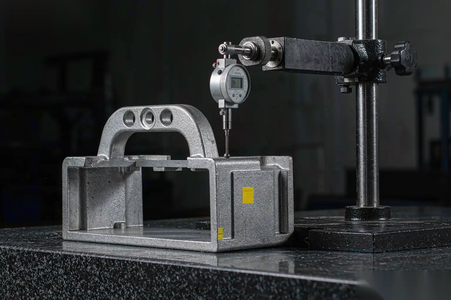
- Instrument. Surface plate with a dial indicator for shop floor checks at 0.05 mm resolution; CMM with a scan for capability studies; optical or laser scan for large panels and for full-field warp maps that show the shape of the error rather than a single number.
- Timing. Measure at a defined time after casting, typically 24 hours, and state it. Measuring a freshly cast part and a stabilised part will give different answers, and the customer will measure later than you do.
For capability work, sample at least 30 pieces across at least three production runs and report both the mean and the range. A flatness Cpk below 1.33 on a critical face means the process, not the inspection, needs attention.
Why Warped Parts Break Automated Finishing
This is where warpage stops being a casting problem and becomes our problem.
A robotic grinding or polishing cell works by presenting a part to a rotating abrasive at a controlled force and a programmed path. The path is generated from the nominal geometry. If the actual part deviates from nominal, the cell has three ways to respond, and all three cost something:
- Fixed path, no compensation. The abrasive contacts hard on high spots and not at all in low spots. Result: cut-through on the high areas, residual cast skin in the low areas, and a visible patchwork after polishing. Scrap and rework.
- Compliant force control. A floating or force-controlled spindle follows the surface within its stroke, typically ±5 to ±15 mm of mechanical float or a force band of a few newtons. This absorbs moderate warp well: parts out of flat by up to roughly 0.5 to 1.0 mm on a mid-size part can be finished consistently. Beyond the compliance range, the spindle runs out of stroke or the contact force swings enough to change the cut rate.
- Active path compensation. Probe or scan the part and offset the path. Accurate, and it costs cycle time and capital. Worth it on large panels where warp exceeds the compliance range.
The practical guidance we give customers: specify incoming flatness to the finishing cell as a controlled characteristic, with a number derived from the capability table above and from the compliance range of the cell. If incoming warp is inside the compliance band, a DZ Machinery cell with compliant force-controlled spindles will hold a consistent finish at production cycle time. If it is outside, either the casting process needs the countermeasures in this article, or the cell needs a scanning station, and the cost difference between those two answers is significant.
There is a second effect worth naming. Warped parts do not clamp repeatably. A part that rocks in the fixture moves under grinding force, and the resulting variation shows up as inconsistent edge break and inconsistent gloss. Fixture design for warped parts means compliant or self-aligning locators and clamping over supported areas, not more clamp force.
If you are working on the casting side of this problem, aluminum die casting defects and solutions covers the defect family in context, and robotic deburring versus manual deburring sets out where automation holds up against part variation and where it does not. Our cell range is described under automated surface finishing equipment.
DZ Machinery builds robotic deburring, grinding and polishing cells with compliant force control for die cast and faucet hardware, and we size the compliance range to the actual incoming flatness of your castings. Send us a batch of 30 production parts with a flatness report and we will tell you what the cell can hold and what incoming flatness limit you need to specify.