Aluminum die casting is the workhorse process for LED heat sinks, power electronics heat sinks, motor controller heat sinks, and a long list of consumer and industrial cooling parts. The reasons are the same as for any die cast part: low per-part cost at volume, tight dimensional capability, and the ability to integrate features (mounting bosses, fastener holes, sealing features) that would otherwise be machined or assembled in a secondary operation.
For heat sinks specifically, the alloy matters. A380, A383, and ADC12 are the workhorses — easy to cast, predictable thermal conductivity (around 90 to 100 W/mK in the as-cast condition), and reasonable cost. A384 and A390 (the high-silicon alloys) push thermal conductivity slightly higher but are harder to cast and more expensive.
The thermal performance of a die cast heat sink comes from three design decisions: fin geometry, wall thickness, and interface flatness. Get all three right and the heat sink delivers rated thermal performance at a competitive cost. Get any of them wrong and the heat sink either fails thermal targets or blows up the part cost.
Fin Geometry
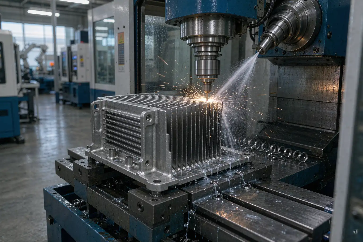
Fin geometry is the biggest lever on thermal performance. The trade-off is simple: thinner fins and tighter pitch give more surface area for a given footprint, but they are harder to cast, easier to warp, and harder to finish.
Fin thickness and pitch
For die cast aluminum heat sinks, the typical envelope is:
| Fin thickness | Fin pitch | Application |
|---|---|---|
| 0.8 to 1.2 mm | 2.5 to 4 mm | High power density, premium LED |
| 1.2 to 1.8 mm | 3 to 5 mm | Standard LED, motor controllers |
| 1.8 to 2.5 mm | 4 to 6 mm | Power electronics, lower density |
| 2.5 to 4 mm | 6 to 10 mm | Cost-driven, low power density |
Fins thinner than 0.8 mm are difficult to fill in cold chamber die casting. The metal cools before the fin is fully formed, leaving the tip short or rounded. The exception is vacuum-assisted die casting, which can push fin thickness down to 0.5 mm, but the cost is significantly higher.
Fin height and aspect ratio
Fin height is set by the part envelope and the casting capability. A safe rule for cold chamber aluminum die casting is a fin aspect ratio (height / thickness) below 8:1. A 2 mm fin can run up to 16 mm tall. A 1 mm fin can run up to 8 mm tall. Push past those and the fin tip starts to drift and the fill becomes unpredictable.
Fin draft
Every fin needs draft for ejection. The standard is 1 to 2 degrees per side for cold chamber die casting. Less than that and the fins drag on ejection. More than that and the fin thickness at the root is 30 percent wider than at the tip, which hurts performance at the tip (where most of the heat transfer happens) and may not fit the envelope.
Skived vs die cast
Skived fin heat sinks (made by machining a block of aluminum) deliver thinner fins (0.3 to 0.5 mm) and tighter pitch, but at much higher cost and much lower volume capability. For thermal-critical applications where the heat sink cost is justified, skived fins win. For cost-critical applications where the heat sink is a commodity, die cast fins win.
Wall Thickness and Uniform Cooling
The second lever is wall thickness. Die cast aluminum parts cool unevenly when walls vary in thickness, and uneven cooling causes three problems: warp, porosity, and dimensional drift.
Uniform wall thickness
A safe rule is to keep wall thickness within ±15 percent of the nominal. A 2.5 mm base with 1.5 mm fins is fine. A 2.5 mm base with 0.8 mm fins will pull the base thin in places and cause porosity. A 4 mm base with 1.5 mm fins will sink at the base and warp the mating surface.
Bosses and mounting features
Bosses for fasteners or standoffs should be 60 to 80 percent of the surrounding wall thickness. A 5 mm boss on a 2.5 mm base will sink and create porosity at the boss root. A 2 mm boss on a 2.5 mm base will fill cleanly.
Ribs and stiffeners
Ribs should be 50 to 70 percent of the wall thickness. Use them to stiffen thin base sections and to break up large flat areas that would otherwise warp. Avoid ribs on both sides of a thin wall — the casting will pull toward the heavier side on cooldown.
Interface Flatness
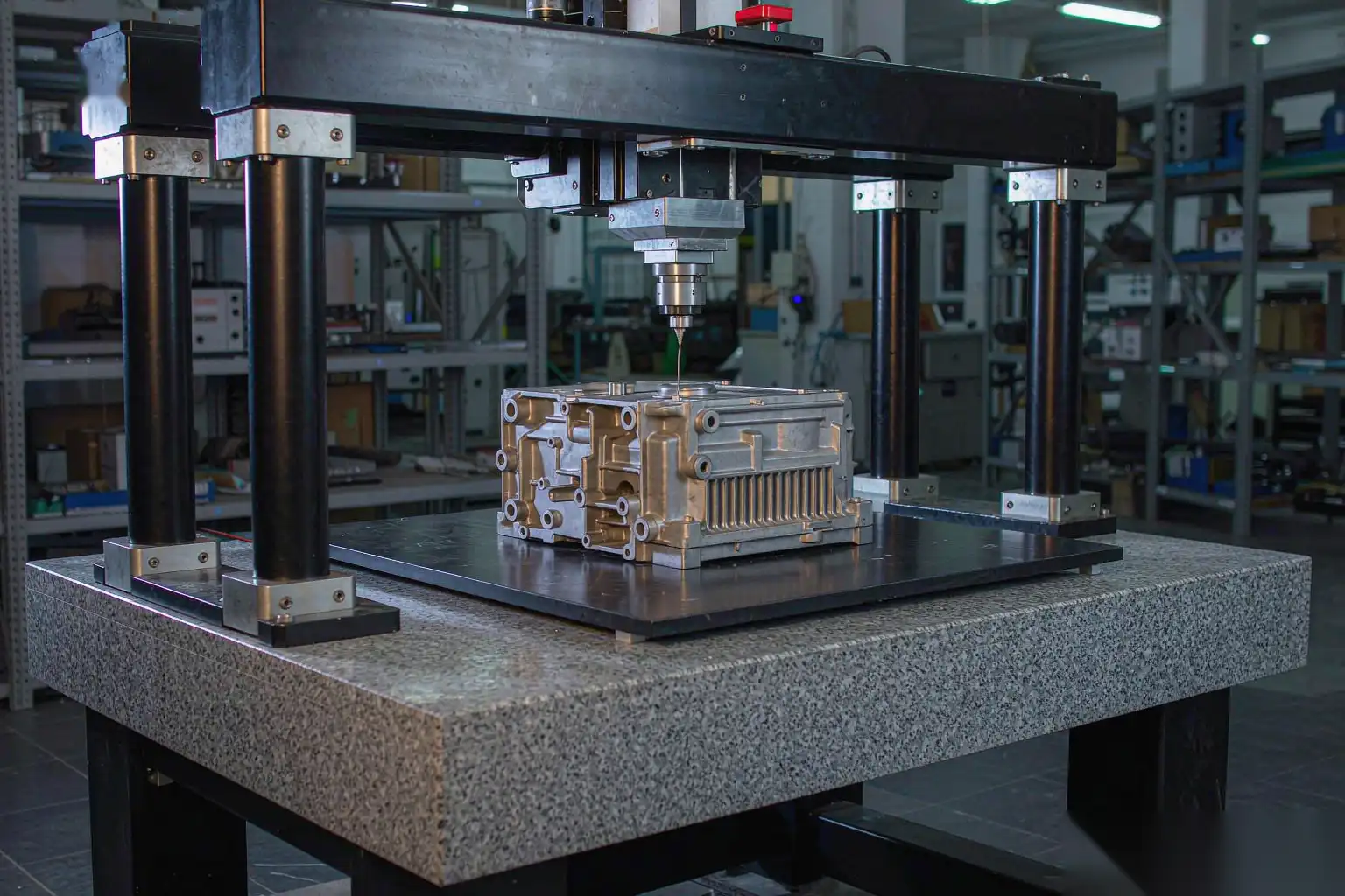
The third lever is the interface flatness, which is the surface that mates to the heat source. A die cast heat sink interface typically has a flatness of 0.1 to 0.3 mm across the footprint. Skived or machined heat sinks deliver 0.02 to 0.05 mm. For LED and motor controller applications where a thermal interface material (TIM) is used, the die cast flatness is usually sufficient. For power electronics where direct mounting is preferred, machined flatness is usually required.
If the die cast heat sink is the interface-critical surface, plan for a post-casting machining operation on the interface. The cost is 5 to 15 percent of the part cost depending on the footprint and the machining depth.
Surface Finish and Thermal Emittance
Die cast heat sinks ship in three finishes:
- As-cast — raw die casting surface. Low thermal emittance (around 0.05 to 0.15). Suitable for enclosed applications or where the heat sink is a structural member, not a thermal radiator.
- Shot blasted — sand or bead blasted to improve surface area. Slightly higher emittance (around 0.2 to 0.3). Common for LED heat sinks.
- Anodized (black or natural) — anodizing raises the emittance to 0.6 to 0.85 in black anodize, which can improve heat dissipation by 10 to 20 percent in natural convection. Black anodize is the standard for premium LED heat sinks.
The anodizing process does not change the geometry significantly (the layer is 5 to 25 µm), but it does change the thermal performance, the cosmetic appearance, and the corrosion resistance. Specify the finish up front — anodizing after the fact is more expensive than anodizing in the original design.
Thermal Interface Material
The TIM is the variable that decides whether the heat sink delivers rated performance. Even the best heat sink on the market will underperform if the TIM is wrong.
Common TIM options for die cast heat sinks:
| TIM | Thermal conductivity | Cost | Typical use |
| Thermal grease | 1 to 5 W/mK | Low | Consumer LED, low power |
| Thermal pad | 1 to 12 W/mK | Low to medium | LED, general electronics |
| Phase change material | 3 to 8 W/mK | Medium | High power LED |
| Thermal adhesive | 1 to 10 W/mK | Medium | Permanent mount |
| Indium foil | 80 W/mK | High | Premium power electronics |
| Graphite pad | 10 to 1500 W/mK (in-plane) | High | High power, in-plane spreaders |
Specify the TIM up front. The TIM choice affects the gap tolerance on the interface, the flatness requirement, and the assembly process.
Common Defects in Die Cast Heat Sinks
The most common defects that buyers see on die cast heat sinks:
- Porosity at the boss root — boss too thick for the surrounding wall. Fix: reduce boss diameter or thicken the surrounding wall.
- Cold shuts at fin tips — fin too thin or fill speed too slow. Fix: increase fin thickness or fill speed, or add vacuum assist.
- Warp on the interface — non-uniform wall thickness or uneven cooling. Fix: redesign for uniform wall, add cooling at the hot spots.
- Sink at the base — heavy section next to thin section. Fix: add a rib on the heavy side to balance the cooling, or thicken the thin section.
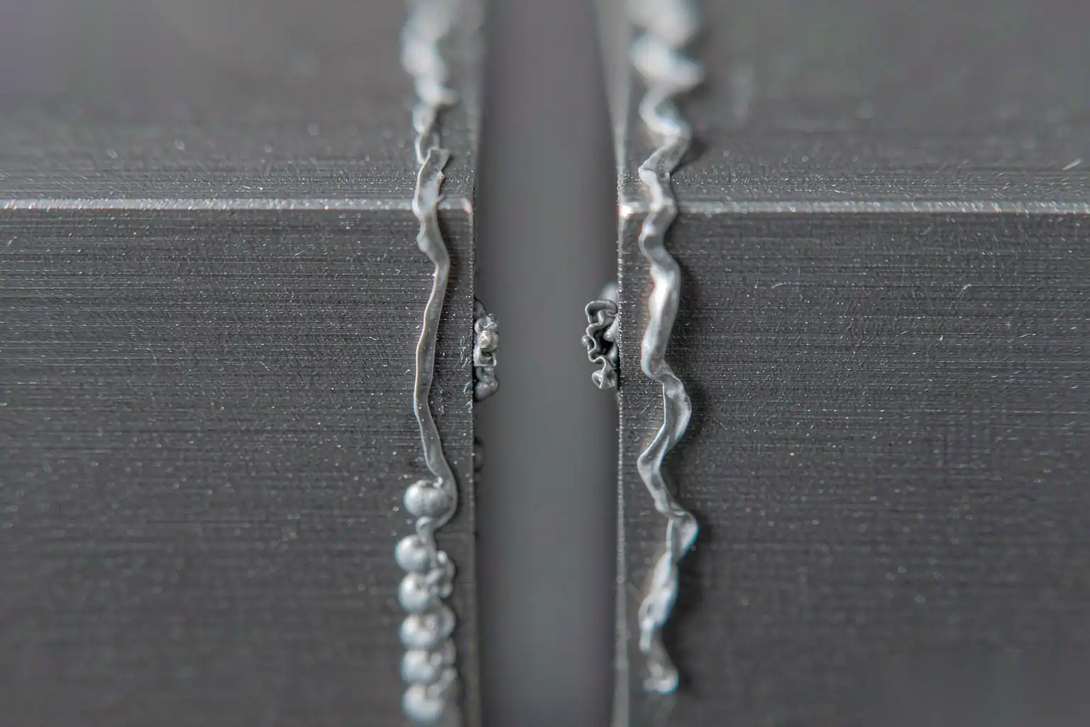
- Flash between fins — worn mold or improper clamping force. Fix: mold maintenance or tonnage adjustment.
- Burrs at fin roots — worn mold or improper ejection. Fix: mold maintenance.
A heat sink with any of these defects will fail thermal qualification. A heat sink with none of them will pass qualification consistently.
How DZ Smart Manufacturing Approaches Heat Sink Design
DZ Smart Manufacturing runs a foundry-to-finishing cell for die cast aluminum heat sinks. The cell handles casting, deburring, interface machining, shot blasting, anodizing, and TIM application. We can deliver a complete heat sink ready to mount, or a raw casting ready for your secondary operations.
For thermal-critical applications where die cast heat sink geometry is borderline, contact DZ for a thermal simulation review. We will run a CFD check on your geometry and tell you whether die cast is the right process or whether skived or extruded is a better fit.
Author: Mr. Lai Dingren, General Manager, DZ Smart Manufacturing. 20+ years in aluminum die casting and thermal management parts. LinkedIn: linkedin.com/in/dzivy
About this article: Educational content. The recommendations are typical industry practice. Always validate thermal performance with your own simulation or prototype testing. The three design levers covered above are the floor for a competitive die cast heat sink, not the ceiling. For programs that push power density higher, the next set of decisions involves alloy selection, vacuum assist, and a CFD-validated fin profile that pushes the aspect ratio beyond what cold chamber die casting normally tolerates.
For plants already shipping a die cast heat sink that is borderline on thermal performance, the cheapest first step is to add a black anodize finish, which lifts natural convection emittance from 0.05 to 0.85 and typically buys 10 to 20 percent more dissipation for a few cents per part. The next step is to clean up the interface flatness with a post-casting machining pass, which lowers the thermal resistance at the bond line. Only after those two changes should a buyer consider a switch to skived or extruded fins, which usually doubles the heat sink cost.