Anodizing Die Cast Aluminum: What the Casting Has to Deliver Before the Tank
Anodizing die cast aluminum is one of the most frequently mis-specified finishes in our industry. A drawing calls for “black anodize, cosmetic grade”, the casting arrives in A380 or ADC12, the anodizer does exactly what they would do for a 6063 extrusion, and the result is a grey, streaky, smutty part that no amount of dye will rescue. The finish house blames the casting, the foundry blames the finish house, and nobody put a number on either side of the argument.
This article is for the people who have to make that argument stop: the process engineer who owns the die, the quality manager who signs the limit samples, and the buyer who has to explain why cosmetic anodize costs three times what a paint line costs. Everything below is about what the casting must deliver before it reaches the tank, because anodizing does not hide anything. It amplifies.
Why Die Cast Aluminum Resists Anodizing
An anodic coating is not a plating layer sitting on top of the metal. It is a conversion of the aluminium itself into aluminium oxide, grown outward and inward from the original surface. That mechanism is exactly why die castings struggle: the substrate is not a homogeneous aluminium crystal lattice, it is a composite of aluminium and second phases.
- Silicon. HPDC alloys carry 7 to 13 percent silicon for fluidity: A383/ADC12 at 9.5 to 11.5 percent, A380 at 7.5 to 9.5 percent, A413 at 11 to 13 percent. Silicon does not anodize. The matrix around it converts to oxide while the silicon particles stay as occluded islands or partly dissolve, leaving a loose grey-to-black residue called smut.
- Copper. A380 carries 3.0 to 4.0 percent, ADC12 around 1.5 to 3.5 percent. Al2Cu and Al2CuMg eutectic phases are nobler than the matrix, so they accelerate local dissolution, drive burning at high current density areas, and give the film a muddy brown tone. Above roughly 2 percent copper, cosmetic anodize stops being realistic.
- Iron. HPDC alloys tolerate 0.9 to 1.3 percent iron to prevent die soldering, arriving as Al5FeSi platelets that are a different colour after anodizing and show as grey streaks following the cavity flow pattern.
- The surface skin. A die casting has a chilled skin 0.05 to 0.30 mm thick with a finer dendritic structure, different silicon distribution and entrained die lubricant. Below it the structure coarsens and porosity rises, so anodizing through the skin exposes a different alloy than the one you qualified.
- Porosity. Electrolyte wicks into connected pores, is difficult to rinse out, and bleeds back during sealing or in service, causing staining and a “weep” that appears days after shipment.
Anodizing is a surface conversion process, and the surface of a die casting is the least representative material in the whole part.
| Element / feature | Typical HPDC range | Effect on anodized appearance | Practical limit for cosmetic anodize |
|---|---|---|---|
| Silicon | 7.5 to 13.0 percent | Grey cast, smut, dull film | Lower is better; below 10 percent preferred |
| Copper | 1.5 to 4.0 percent | Muddy tone, burning, pitting | Below ~1.0 percent for Type II cosmetic |
| Iron | 0.9 to 1.3 percent | Grey streaks, pitting at platelets | Below 0.6 percent for bright work |
| Magnesium | 0.2 to 0.5 percent | Slight haze above 0.6 percent | Keep under 0.5 percent |
| Zinc | up to 3.0 percent | Mottling, uneven dye uptake | Keep under 1.0 percent |
| Near-surface porosity | — | Bleed-out, spotting, pinholes | No connected pores within 0.3 mm of surface |
Alloy Selection: What Actually Anodizes
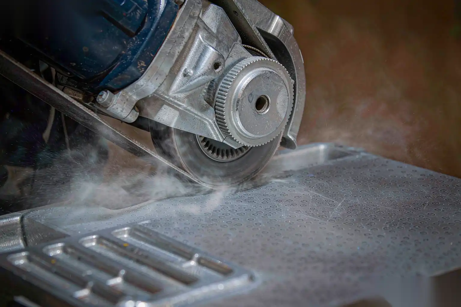
If the part must be cosmetically anodized, the alloy decision has to be made before the die is cut, and it usually means moving away from the general purpose alloys.
For die cast parts that must anodize, we look for alloys in the AlSi9MgMn family: silicon 9 to 10.5 percent to keep fill behaviour acceptable, magnesium 0.2 to 0.5 percent, manganese 0.4 to 0.8 percent to suppress die soldering without adding iron, and critically copper below 0.05 percent, iron below 0.15 to 0.20 percent, zinc below 0.10 percent. These are high purity, low-iron alloys with strontium modification, and they fill noticeably worse than ADC12. Expect injection temperatures of 660 to 700 degrees Celsius rather than 620 to 650, tighter fill time windows because of the wider mushy zone, more aggressive lubrication management because low iron means more soldering tendency, and vacuum assistance on the shot end.
The alternative is to change the process rather than only the alloy. A356 (silicon 6.5 to 7.5 percent, copper below 0.20 percent, magnesium 0.25 to 0.45 percent) with strontium modification and T6 treatment anodizes to a clean uniform grey and takes dye well; it is the standard answer when geometry allows low pressure or gravity casting instead of HPDC. We cover those trade-offs in our die cast aluminum complete guide.
Whichever route is chosen, freeze the specification in the drawing: alloy designation with composition limits, modification practice, and a near-surface porosity criterion. If the porosity requirement is not written down, it does not exist.
What the Casting Must Deliver: Acceptance Criteria Before Prep
We push customers to define four numbers before a single part is ground.
- Near-surface porosity. No gas pore larger than 0.2 mm within 0.3 mm of a cosmetic surface, and no connected porosity reaching one. Verified by microsection at first article, then by X-ray sampling to ASTM E505 or reference radiographs to ASTM E155.
- Skin integrity. Enough stock must come off in prep to cut through the as-cast skin: 0.05 to 0.15 mm on a well-fed face, up to 0.30 mm near gates and heavy sections. If the wall is 1.8 mm and the cosmetic face needs 0.25 mm removed, the die has to be designed with that stock in it.
- Roughness before anodize. Ra 0.2 to 0.4 micrometres for bright or black, Ra 0.8 to 1.6 micrometres for satin. A 12 micrometre Type II film adds roughly 0.1 to 0.3 micrometres Ra on top of the mechanical finish.
- Dimensional allowance. The film grows about half outward and half inward, so a 20 micrometre coating adds roughly 10 micrometres per surface and 20 micrometres on a diameter. Bores and threads must be masked or compensated, and masking has to be designed into the fixture.
If any of those four is undefined, the anodizer will define it for you, usually after the first scrap batch. The porosity interaction is covered further in aluminum die casting porosity causes and solutions.
Route Comparison: Choosing the Anodizing Process
| Route | Bath and window | Typical thickness | Appearance on HPDC | Best application |
|---|---|---|---|---|
| Type II sulfuric, clear | 165 to 200 g/L H2SO4, 18 to 22 degrees C, 1.2 to 1.5 A/dm2, 20 to 40 min | 8 to 18 micrometres | Grey, smut risk high on ADC12 | Low-copper low-iron alloys, functional corrosion protection |
| Type II, dyed black (organic) | Type II base 10 to 15 micrometres, dye 50 to 60 degrees C, 10 to 20 min | 12 to 18 micrometres | Deep black only on clean alloy; mottles on high Si | Consumer hardware where UV exposure is limited |
| Type II, electrolytic colour (tin or nickel salts) | 15 to 20 micrometres base, then AC electrolytic colouring | 15 to 25 micrometres | Bronze to black, much more uniform | Architectural and exterior hardware |
| Type III hardcoat | 2.0 to 4.0 A/dm2, 0 to 5 degrees C, with organic acid additives, 30 to 60 min | 25 to 75 micrometres | Dark grey to brown, rough, burning common above 25 micrometres | Wear surfaces, not cosmetic |
| Bright dip plus anodize | Chemical or electrochemical brightening before Type II | 5 to 12 micrometres | Mirror only on low-Si, low-Fe alloys; etches pores open | Small decorative trim |
| Mechanical polish plus anodize | Abrasive sequence to Ra below 0.1 micrometres, then Type II | 8 to 15 micrometres | Best control; the only route that levels the substrate first | Faucet bodies, door hardware, visible bezels |
The last row is the one that matters for most of our customers. Bright dip attacks the whole surface chemically, opening every pore and every silicon particle at once. Mechanical polish is selective: it levels the surface, closes the mouths of small pores by plastic flow, and removes the chilled skin to a controlled depth. It costs more in capital, but it is the only route where someone decides where material comes off.
The Mechanical Preparation Sequence
Prep for cosmetic anodize is a stock-removal sequence, not a buffing operation. Each stage has a target roughness and a target depth removed.
- Gate and parting line removal. 36 to 60 grit ceramic alumina belt, 25 to 30 m/s. Removes stock fast, not fine.
- First levelling. 80 then 120 grit on a hard contact wheel (Shore A 80 to 90) to keep the surface flat. Skipping 80 doubles cycle time, because 120 cannot remove 60 grit scratches quickly.
- Progressive refinement. 180, 240, then 320 grit, each step fully removing the previous scratch pattern. A practical rule: each successive grit should remove 1.5 to 2 times the previous scratch depth, otherwise you are polishing damage instead of removing it.
- Pre-polish. 400 to 600 grit, then greaseless compound on a sewn buff or non-woven abrasive, to Ra 0.2 to 0.4 micrometres.
- Colour buff. Sisal wheel with tripoli for cut, then loose cotton with fine aluminium oxide or white rouge for colour, at 25 to 35 m/s peripheral speed.
- Vibratory or drag finishing. Plastic or ceramic media, 2 to 4 hours, mildly alkaline compound at pH 8.0 to 9.5. This uniformizes rather than removes stock, taking off only 5 to 20 micrometres.
| Grit / media | Nominal Ra after stage (micrometres) | Stock removed (mm) | Typical belt or wheel speed | Notes |
|---|---|---|---|---|
| 60 grit ceramic | 2.5 to 3.5 | 0.15 to 0.40 | 25 to 30 m/s | Gate and flash removal |
| 80 grit | 1.8 to 2.5 | 0.08 to 0.15 | 25 to 30 m/s | Levelling cut |
| 120 grit | 1.2 to 1.8 | 0.04 to 0.08 | 22 to 28 m/s | Removes 80 grit pattern |
| 180 grit | 0.8 to 1.2 | 0.02 to 0.05 | 22 to 28 m/s | First refinement |
| 240 grit | 0.5 to 0.8 | 0.01 to 0.03 | 20 to 26 m/s | Pre-polish |
| 320 to 400 grit | 0.3 to 0.5 | 0.005 to 0.015 | 20 to 26 m/s | Satin finish end point |
| 600 grit plus greaseless | 0.15 to 0.30 | 0.003 to 0.008 | 18 to 24 m/s | Bright anodize substrate |
| Sisal plus tripoli | 0.08 to 0.15 | 0.002 to 0.005 | 25 to 35 m/s | Cut buff |
| Loose cotton plus rouge | 0.04 to 0.10 | less than 0.002 | 25 to 35 m/s | Colour buff |
Two details deserve instrumentation rather than operator judgement. Below about 18 m/s a belt smears aluminium instead of cutting it, and smeared metal folds over pores that look perfect until the part comes out of the etch. Above roughly 0.4 MPa contact pressure, localized heat re-solutionizes the surface layer, and that layer anodizes to a different colour. Specify force-controlled contact and a defined infeed per pass, not “press harder until it shines”.
Common Defects and Their Root Causes
| Defect | What it looks like | Root cause | First corrective action |
|---|---|---|---|
| Smut | Grey to black powdery film that wipes off | Silicon and alloying phases left on the surface after anodizing | Increase desmut (nitric or fluoride-based), reduce silicon or reduce film thickness |
| Burning | Chalky white, rough patches at edges, threads and high current areas | Local current density too high, bath too warm, copper-rich phases | Reduce current density to below 1.2 A/dm2, improve bath agitation and cooling, check racking contact |
| Uneven colour | Mottled or blotchy dye uptake | Variable film thickness, residual stress, uneven prep, contaminated rinse | Standardize prep sequence, verify film thickness at multiple points, check rinse conductivity |
| Orange peel | Wavy surface visible after anodize | Over-aggressive etch or bright dip, coarse grain, over-polishing heat | Reduce etch time and temperature, control prep heat input |
| Pitting | Small craters after anodize | Iron-rich phases dissolving, over-etch, chloride in bath | Lower iron in alloy, shorten etch, control bath chloride below 50 ppm |
| Bleed-out staining | Coloured stains appearing days later | Electrolyte trapped in connected porosity | Improve porosity specification, extend rinse, use vacuum-assisted sealing |
| Dye streaking | Directional streaks following polish lines | Polish pattern not uniform, smeared metal | Fix grit progression, verify final Ra and direction |
| Dull film on edges | Edges duller than flats | Burning from edge current concentration, edge break too sharp | Specify a minimum edge radius, shield or reduce current density |
Process Control and Verification
Once the sequence is fixed, control it on a short list of measurements taken at defined frequencies and recorded against part number, not against shift.
- Bath chemistry: free sulfuric acid and dissolved aluminium, the latter held below 12 to 15 g/L because film hardness and dye response degrade above that.
- Bath temperature logged continuously, chiller sized for peak load. A 5 degree excursion on a 20 degree bath changes film density measurably.
- Coating thickness: eddy current per ISO 2360 for production checks, cross-section microscopy per ISO 1463 for first article and disputes.
- Seal quality: acid dissolution per ISO 3210 with mass loss at or below 30 mg/dm2, or the ISO 2143 dye spot test for rapid screening.
- Colour: spectrophotometer against master limit samples, with delta E below 1.5 between adjacent surfaces on the same part and below 2.5 against the master.
- Corrosion: neutral salt spray per ISO 9227, written as hours to a defined pit count per unit area rather than a vague “passes 500 hours”.
The finish callout on the drawing should reference a recognised standard rather than a photograph. Our overview of die casting surface finish standards explains how to write it so supplier and customer read the same number.
Where Robotic Preparation Changes the Equation
The prep sequence above is deterministic: fixed grits, fixed force, fixed path, fixed time per stage. That is exactly the work humans do inconsistently and robots do repeatably.
In the cells we build at DZ Machinery, the sequence runs on a six-axis robot with a force-controlled floating spindle and an automatic media changer. What we measure on cosmetic anodize lines:
- Consistent depth of cut. Force control holds contact pressure in a narrow band, so the skin is removed uniformly instead of heavily where the operator leaned in. That alone removes most uneven-colour complaints.
- Repeatable grit progression. The automatic changer enforces the sequence; skipping 120 grit is structurally impossible because the tool is not in the magazine.
- Defined cycle time. A faucet body or hardware housing that takes an operator 90 to 150 seconds through five manual stages runs in 45 to 70 seconds on a two-station cell, with the robot working one station while the operator loads the other.
- Scrap reduction. Manual cosmetic prep scrap is commonly 4 to 8 percent, mostly from breakthrough at edges and inconsistent blending. Force-controlled cells run the same parts at 1 to 2 percent.
- Traceability. Contact force, spindle load and cycle count can be logged per part and correlated back to the anodize batch when a colour issue appears.
The economics depend on volume and on how many cosmetic faces the part has. One visible face at moderate volume may not justify a cell. Three visible faces, a tight delta E requirement and monthly volume above roughly 15,000 pieces almost always do, particularly against three shifts of skilled polishers whose work varies by the hour.
DZ Machinery builds mechanical preparation cells for anodize-grade die castings, from single-robot grinding stations to complete lines running band saw, CNC, multi-stage robotic grinding, automatic polishing and inspection. If you are specifying a cosmetic anodize, the most useful next step is a finish study on your own parts: send us the drawings, the alloy and your acceptance samples, and we will run the sequence, measure Ra and stock removal at each stage, and give you a cycle time and projected scrap rate before you commit to tooling.