Aluminum Casting Weld Repair: When It Works, When It Fails, and What It Costs
Every foundry and every machine shop eventually asks the same question about a defective casting: can we weld it? The honest answer is that it depends on the alloy, the process that made the part, and what the defect actually is. Welding a sand cast Al-Si housing is routine. Welding a high pressure die casting to fix gas porosity is, in most cases, a way of turning a visible defect into an invisible one. This article sets out the decision rules we use, the parameters that actually matter, how to inspect the result, and a worked example of the repair-versus-scrap economics.
We are a robotic grinding and polishing equipment builder, not a weld repair shop, but we live in the same plant. Roughly a third of the parts we process in customer cells have been weld repaired upstream, and we see what happens to them under a belt, under a buff, and after plating. That downstream view is useful: it is where bad weld repairs become visible.
The First Question: What Made the Part?
Casting process determines gas content, and gas content determines weldability. This is the single most important variable, and it is almost never stated on the drawing.
| Casting process | Typical gas content | Weld repair prognosis |
|---|---|---|
| Sand cast (gravity) | Low, 0.10–0.25 ml/100 g | Good. Routine repair with TIG or MIG. |
| Permanent mold / gravity die | Low to moderate | Good for isolated defects, fair for clustered porosity. |
| Low pressure die casting | Low, 0.15–0.30 ml/100 g | Good, best of the pressure routes. |
| Squeeze cast / semi-solid | Very low, often under 0.10 ml/100 g | Excellent. Densification reliable. |
| High pressure die casting (HPDC) | High, 1–5 ml/100 g is common | Poor. Surface-breaking porosity usually reappears or blows out. |
High pressure die castings fill in 40 to 120 ms with turbulent flow. Air and die lubricant are entrained mechanically and dissolved hydrogen is present from the melt. When you bring a TIG arc to 6,000 to 10,000 K over that material, the entrained gas expands, the oxide film that is already dispersed through the part becomes a defect population of its own, and the weld pool boils. What you get is a repair that looks sound on the surface and is full of fine porosity underneath, which then shows up as a haze or a pinhole row after polishing or as a leak at final test.
We are not saying HPDC can never be welded. We are saying the default answer for conventional HPDC should be no, and the exception should be justified with data: a low gas variant, a vacuum-assisted process, and a defect located in a thick, low-stress section. The mechanism behind that gas content, and the melt and vacuum practices that reduce it, are covered in our aluminum die casting porosity analysis.
Alloy Weldability
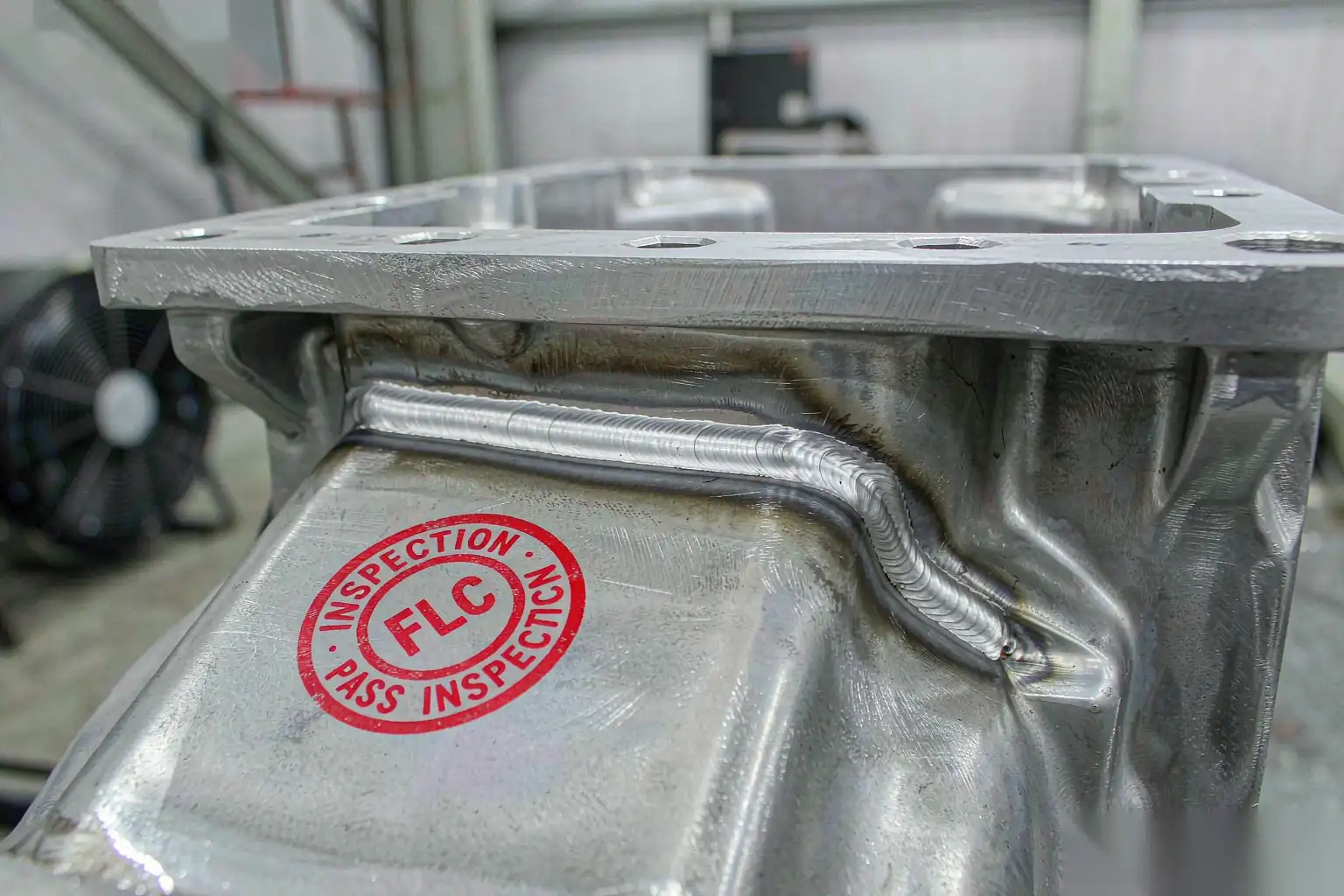
Al-Si Alloys (A356, A413, ADC12 / A383, AlSi9Cu3)
Silicon improves fluidity and reduces hot cracking, which makes Al-Si the most weldable family. The near-eutectic compositions (around 11 to 13 percent Si) are the friendliest: low shrinkage, wide freezing range control, and good puddle behavior.
- A356 (AlSi7Mg): excellent weldability, the reference case. Standard filler 4043, or 5356 if you need higher ductility and are willing to accept lower color match after anodizing.
- ADC12 / A383 / AlSi9Cu3(Fe): weldable but with caveats. Copper content raises hot cracking sensitivity, and iron above roughly 1.0 percent forms plate-shaped intermetallics that nucleate cracks in the heat affected zone. These are the alloys most common in HPDC, which is exactly why the gas problem and the alloy problem arrive together. Composition limits and mechanical properties for the most widely used of them are set out in our A380 aluminum alloy properties guide, and the wider family comparison is in the aluminum alloy die casting guide.
Al-Cu Alloys (2xx series equivalents, A201, A206)
Poor weldability in repair contexts. The wide freezing range between liquidus and solidus promotes hot cracking, and the heat affected zone loses strength badly. Casting repair on Al-Cu usually requires preheat above 200 C, tight interpass control, and a post weld solution treatment plus artificial ageing to recover properties — which means you are heat treating a finished casting, with all the distortion and cost that implies. In most production environments the answer is scrap.
Al-Mg Alloys (5xx, A518)
Good weldability with 5356 filler, but the magnesium content makes the oxide heavier and demands more aggressive cleaning. Also prone to porosity from absorbed hydrogen if the part has been in service.
Zinc and Multi-Alloy Parts
A note for faucet hardware: zinc alloy die castings are not weld repaired in any production process we have seen. Braze and solder fill exist for cosmetic blending, and that is a different article. Do not let a supplier offer “weld repair” on a zinc handle.
The Defect Matters More Than the Alloy
- Cold shut or cold flow at a surface: repairable if the section is thick enough to take a groove. Route out to sound metal, dye penetrant check the groove, then fill.
- Misrun or unfilled section: repairable; this is essentially a build-up operation rather than a defect repair.
- Isolated blowhole or sand inclusion: the best case. Route to full depth plus 1 to 2 mm, fill in two or three passes.
- Distributed gas porosity: not repairable in HPDC. You cannot route out a defect that is everywhere, and welding over it makes it worse.
- Hot tear or crack: repairable only after you have drilled a stop hole at each end and confirmed by penetrant that the crack terminates. Welding along an unterminated crack simply extends it.
- Dimensional error: weld build-up then machine is technically possible and almost never economical, because the heat input distorts the very dimension you were trying to fix.
Process Comparison and Parameters
TIG (GTAW)
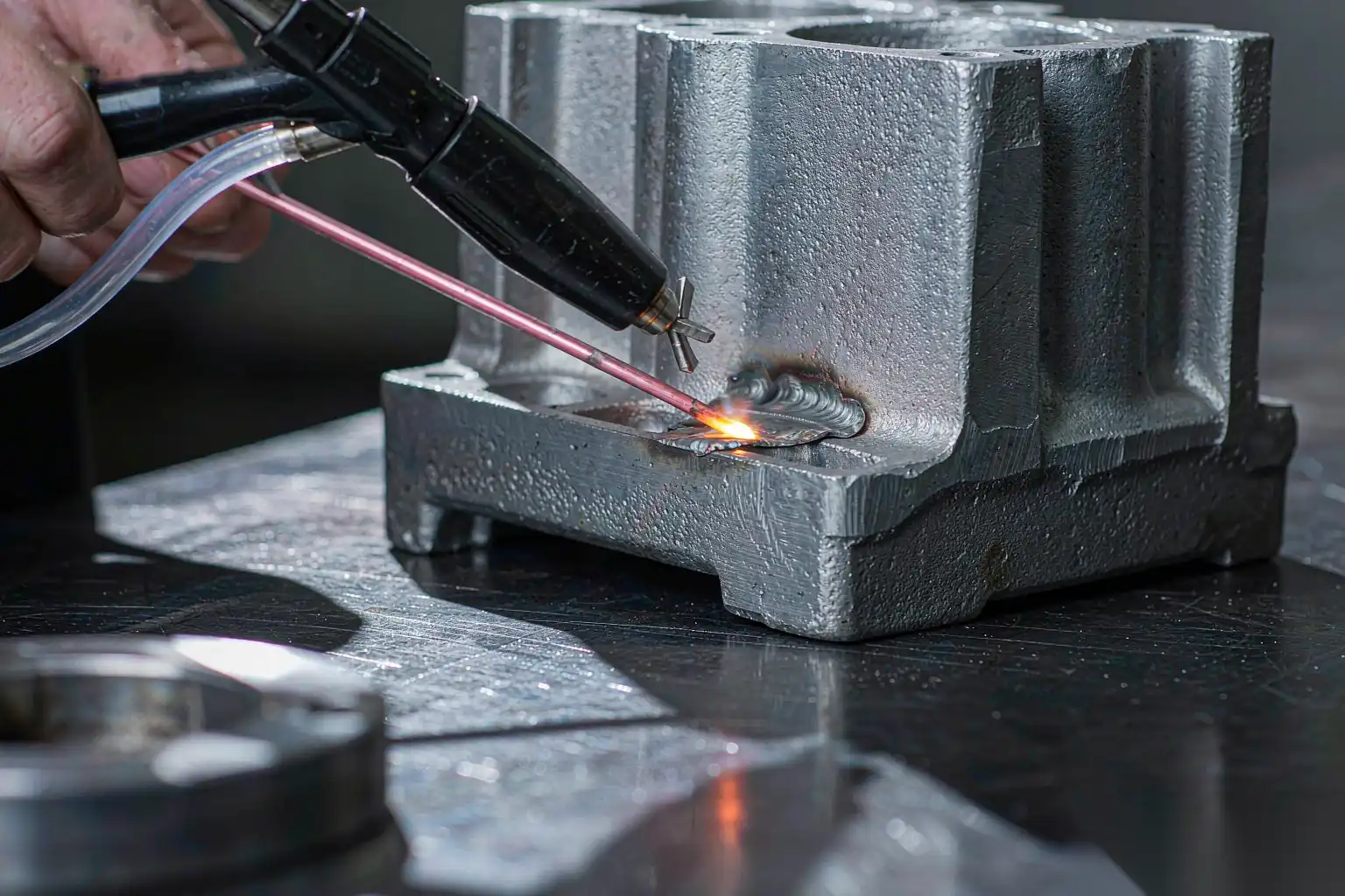
The default for cast aluminum repair. AC with high frequency start, balanced or slightly electrode-negative cleaning action, pure argon shielding.
| Parameter | Thin section, under 6 mm | Medium, 6–15 mm | Heavy, over 15 mm |
|---|---|---|---|
| Filler diameter | 1.6–2.4 mm | 2.4–3.2 mm | 3.2–4.0 mm |
| Current (AC) | 60–110 A | 120–190 A | 190–260 A |
| AC balance | 65–70% EN | 70–75% EN | 70–75% EN |
| Frequency | 100–150 Hz | 80–120 Hz | 60–100 Hz |
| Argon flow | 8–10 L/min | 10–14 L/min | 12–16 L/min |
| Preheat | 100–120 C | 120–180 C | 150–200 C |
| Interpass max | 150 C | 180 C | 200 C |
The two numbers people get wrong are preheat and interpass. Under 100 C preheat on a 12 mm section means the arc spends its first seconds just heating the part, penetration is shallow, and the first pass sits on top of an un-fused groove. Over 200 C interpass on a copper-bearing alloy grows the heat affected zone and the crack risk.
MIG (GMAW)
Faster deposition, less operator skill, more spatter and more porosity risk on gassy material. Use it for build-up on thick sections, not for cosmetic or pressure-tight repair.
- Transfer mode: pulsed spray for anything you care about; short arc is too cold for aluminum and gives lack of fusion.
- Wire: 4043 or 5356 at 1.2 mm diameter for most repair work.
- Wire feed and voltage must be matched so the arc runs in spray or pulsed spray: roughly 6 to 9 m/min at 21 to 26 V for 1.2 mm wire.
- Argon at 16 to 20 L/min; helium-argon mixes (25 to 50 percent He) help on thick sections.
- Push the torch, never pull. Pulling on aluminum drags the oxide shield behind the puddle and pulls in air.
Cold Metal Transfer (CMT)
A controlled short-circuit process that retracts the wire on each short circuit, giving very low heat input — typically 15 to 30 percent less than conventional pulsed MIG at the same deposition rate. For cast aluminum repair this is genuinely useful:
- Reduced dilution into the base metal, so less gas and fewer intermetallics pulled into the weld.
- Low distortion, which matters when the repair is on a machined face with a tolerance to hold.
- Good bridgeability on routed-out grooves with variable width.
- Deposition is lower than standard MIG, so it is not the tool for filling large volumes.
If you are repairing low-pressure or gravity cast parts with a mix of thin and thick sections, CMT is usually the right choice. If you are repairing HPDC porosity, no process will save you.
Filler Selection
| Filler | Composition | Use when | Color after anodize |
|---|---|---|---|
| 4043 | Al-5Si | General purpose, best crack resistance, most Al-Si castings | Grey, reasonable match |
| 4047 | Al-12Si | Near-eutectic castings, lower melting range, better fluidity | Grey |
| 5356 | Al-5Mg | Higher strength and ductility needed, good color after anodize | Bright, closer match |
| 4145 | Al-10Si-4Cu | Copper-bearing castings, higher strength | Dark |
Rule of thumb for repair: match the base metal’s silicon level where possible, use 4043 when hot cracking is the concern, and use 5356 only when the joint needs ductility or must disappear after anodizing. Do not use 5356 on a part that will see sustained service above 65 C, because the magnesium-bearing weld metal is susceptible to sensitization and stress corrosion.
One practical note: 4043 and 5356 must never be mixed in the same joint. The Mg2Si that forms makes the weld brittle.
Preparation: Most Failures Happen Here
Weld repairs fail at preparation far more often than at welding.
- Degrease. Vapor degrease or alkaline clean, then rinse. Die lubricant residue in the groove is a hydrogen source.
- Mechanically remove the oxide. Stainless steel wire brush used in one direction only, or a rotary burr. Aluminum oxide melts at roughly 2,050 C compared with 660 C for the metal; if it stays in the joint it becomes an inclusion.
- Route the defect out. Use a burr or a die grinder, not a grinding wheel, and keep the groove U-shaped with a minimum 3 mm radius at the bottom. A V-groove with a sharp root is a lack-of-fusion generator.
- Penetrant check the groove. Do this before welding, not after. If the groove still shows indications, keep routing.
- Preheat and verify. Temperature indicating crayon or contact pyrometer, not a guess. Preheat evenly and locally, not with a torch sweeping over the whole part.
- Peen between passes on multi-pass repairs to relieve shrinkage stress, then brush before the next pass.
Post Weld Inspection
The inspection method should be selected from the consequence of failure, not from habit.
- Dye penetrant (PT): mandatory minimum on every repair. Sensitive to surface-breaking cracks. Note that aluminum castings are prone to penetrant entrapment in porosity, which shows as a diffuse blotch rather than a crisp line; train the inspector to tell the difference, or you will scrap good repairs and pass bad ones.
- Radiography (X-ray): the only practical way to find subsurface porosity in a repair. ASTM E505 reference radiographs for aluminum castings give a shared language; specify an acceptable grade in the repair procedure rather than “sound weld.”
- Pressure or leak test: required for any pressure boundary. Air decay at 1.5 times working pressure with a defined decay limit over a defined time, or a water dunk at 3 to 5 bar for smaller parts. Note the standard trap: a repair that passes a 30-second air decay test may still leak over a service life, because the leak path is through interconnected porosity that pressurizes slowly.
- Helium leak test: when the allowable leak rate is below roughly 1×10^-4 mbar·L/s. Overkill for most castings, essential for refrigerant and some automotive applications.
- Hardness and tensile: on procedure qualification, not per part. Check the heat affected zone hardness drop; a 20 percent loss across the HAZ on an as-cast T5 alloy is normal and is a design input.
Document the repair: location, alloy, filler, process, operator, parameters, heat treatment, and inspection result. Repairs done without a record cannot be root-caused later, and a plant that does unrecorded repair is a plant that will ship a bad repair.
Cosmetic Blending After Repair
This is where we get involved. A weld repair on a visible face has to be blended, and the blending is where the repair either disappears or announces itself.
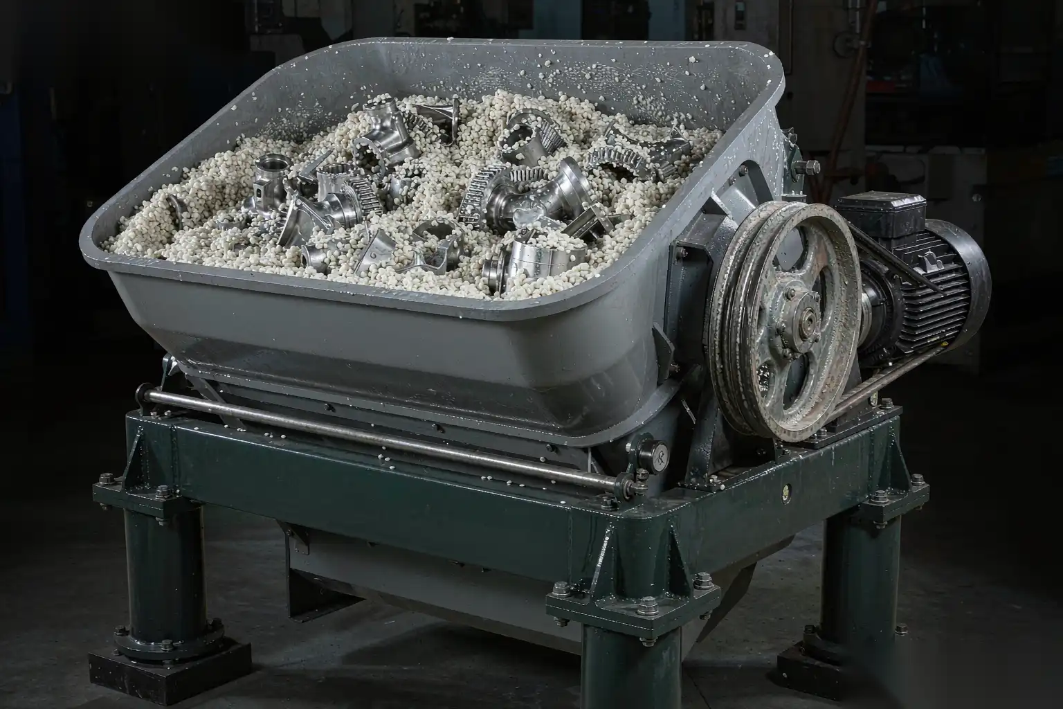
- The as-welded bead typically stands 1.5 to 3 mm proud. Rough grind with 60 to 80 grit, then 120, then 180 or 240 depending on the final finish.
- On a part destined for chrome plating, any residual porosity in the repair will outgas through the plating bath and leave a pinhole row. Buffing compound packed into the porosity hides it until the part is heated or plated. This is the most common cause of “the repair looked fine until plating.”
- Over-buffing is the second failure mode. Polishing a repair generates local heat, and soft weld metal smears rather than cuts, producing a depression that is visible in reflected light as a low spot or a “ghost” of the repair. Limit the contact pressure, keep the wheel speed in the 1,800 to 2,600 m/min range for aluminum, and do not dwell.
- Robotic polishing with force-controlled floating spindles handles repairs better than hand work precisely because the pressure and the path are constant. The robot does not press harder on the soft spot out of habit. That said, consistency cuts both ways: a robot will reproduce the same result on every part, and if the underlying repair quality varies, the variation in the finished surface becomes measurable and obvious. That is a feature, not a bug — it is how you find out your repair process is unstable.
Repair or Scrap: A Worked Example
Take a low pressure cast AlSi7Mg pump housing.
- Casting and machining value at the point of defect discovery: 38.00 USD
- Defect: two blowholes, 4 mm and 6 mm diameter, on a non-cosmetic outer wall in a 9 mm section, discovered after rough machining
- Scrap cost: 38.00 USD sunk, plus a replacement casting at 6-week lead time and a machine slot that is now idle
Repair route:
| Step | Labor (min) | Rate (USD/h) | Cost (USD) |
|---|---|---|---|
| NDT to define extent (PT + X-ray) | 12 | 45 | 9.00 |
| Routing and groove preparation | 15 | 45 | 11.25 |
| Preheat and setup | 20 | 45 | 15.00 |
| TIG weld, 3 passes | 25 | 55 | 22.92 |
| Post weld PT and X-ray | 12 | 45 | 9.00 |
| Blend grind and polish | 18 | 45 | 13.50 |
| Final leak test | 8 | 40 | 5.33 |
| Consumables, argon, filler, abrasives | — | — | 6.40 |
| Total repair cost | 110 min | 92.40 |
Repair saves 38.00 USD of sunk value at a cost of 92.40 USD, and that comparison is not the right one. The right comparison is against the full cost of replacing the part: new casting at 41.00 USD (raw plus casting margin), plus machining at 26.00 USD, plus handling and scheduling, and a 6-week delay. So the repair at 92.40 USD is clearly the right call.
Now change two variables and see what happens.
- Same defect on a high pressure die casting. The weld has an expected success rate of perhaps 40 to 60 percent on the first attempt. Expected cost becomes 92.40 / 0.5, roughly 185 USD, plus a second X-ray cycle, and you still have a part with an unknown fatigue life in a pressure boundary. Scrap is now correct.
- Same defect on a cosmetic class A face. Add 45 minutes of cosmetic blending and a re-polish of the surrounding area to blend the transition — roughly 34 USD — and add a rework risk of 25 percent. Repair total around 145 USD with a 25 percent chance of a second attempt. Still worth it on a 67 USD replacement part, but only just, and only if you have a documented cosmetic limit sample to blend against.
- Same defect found before machining. Repair cost drops to about 55 USD because there is no machined surface to protect, and the risk of distortion mattering drops to near zero. This is the real lesson: the earlier in the process you find the defect, the more often repair is the right answer.
A useful decision rule that falls out of this: repair is economical when the defect is found early, the section is thick, the alloy is Al-Si and low gas, the defect is localized, and the face is not class A. Every one of those conditions that fails pushes you toward scrap. On HPDC, the gas condition fails by default.
Where Automation Changes the Calculation
Two things shift the economics. First, automated inspection finds defects earlier — a camera or a leak station right after casting, rather than a visual check after machining — and earlier detection is the single biggest lever in the table above. Second, automated blending and polishing makes the cosmetic step predictable instead of dependent on which operator is on shift. When the blending step is repeatable, you can put a real number in the repair cost model instead of a range, and the repair-or-scrap decision becomes arithmetic rather than opinion.
DZ Machinery builds robotic deburring, grinding and polishing cells for die cast and faucet hardware, including stations for post-repair blending where the cycle time and the contact force are fixed parameters rather than operator habits. If you are running a weld repair loop today and the cosmetic outcome varies by shift, send us the part drawings and your current repair sequence, and our engineering team will tell you where the variation is coming from and what a repeatable cell would look like.