Automated robotic deburring solutions—specifically engineered for soft non-ferrous metals—solve these production bottlenecks. By integrating real-time force-controlled compliance, custom cutting geometry, and optimized spindle speeds, manufacturers achieve precision flash removal without damaging fragile casting walls. This technical guide outlines the exact tooling selection, parameters, force-control settings, and cell architecture required to successfully automate zinc die casting finishing.
Why Zinc Alloy Deburring Requires a Unique Approach
Most common zinc alloys (such as ZAMAK 2, ZAMAK 3, ZAMAK 5, ZAMAK 8, and ZA-12) possess exceptionally low melting points (~380°C–390°C) and high fluidity. While these traits make zinc ideal for intricate, thin-walled die castings, they introduce severe physical constraints during automated edge finishing:
- High Ductility and Stringy Flash: Parting line burrs on zinc castings typically range from 0.05 mm to 0.35 mm in thickness. Due to high material elongation, standard cutting tools often fold or push the burr flat against the surface instead of shearing it cleanly off.
- Low Surface Hardness (50–90 HB): Zinc’s softness renders it vulnerable to surface gouging. Rigid robotic toolpaths without dynamic force feedback inevitably cut into the nominal casting profile whenever part dimensions fluctuate slightly.
- Galling and Built-Up Edge (BUE): Zinc exhibits a strong chemical affinity to adhere to metallic cutting edges under mechanical friction and heat buildup. Once zinc welds onto the flutes of a carbide burr, cutting efficiency drops drastically, leading to rough surfaces and premature tool failure.
- Ultra-Thin Wall Profiles: Precision zinc castings (e.g., electronic shielding, automotive housings) frequently feature wall thicknesses under 1.2 mm. Applying uncalibrated mechanical force risks deforming or fracturing the part structure.
Key Automated Deburring Technologies for Zinc Alloys
1. Dynamic Active Force Control & Compliant Systems
The core technology enabling automated zinc deburring is dynamic force compliance. Rather than driving a rigid tool along a fixed spatial path, a 6-axis industrial robot equipped with a closed-loop pneumatic active force actuator or an integrated 6-axis Force/Torque (F/T) sensor responds instantly to contact resistance.
Field-Tested Parameter: For zinc alloys, contact forces must be maintained precisely between 3 N and 8 N (compared to 15–30 N for aluminum and 40–80 N for cast iron). Maintaining this low, constant pressure allows the tool to follow the natural contour of the casting, shearing off flash precisely at the parting line without gouging the base metal.
2. Pneumatic & Servo Floating Deburring Heads
To accommodate dimensional tolerances, shrink variations, and minor die-alignment drifts (±1.0 mm to ±3.0 mm), floating deburring spindles provide radial and axial compliance. Utilizing adjustable air pressure, the floating mechanism acts as a soft mechanical buffer. When the spindle traverses over a heavier flash section, the floating head flexes dynamically while keeping the cutting pressure within the safe pre-set limit.
3. Optimized High-Speed Electric Spindles & Carbide Tooling
High spindle speeds are crucial to shear soft zinc burrs before thermal softening occurs. Electric spindles running between 12,000 RPM and 24,000 RPM deliver the linear cutting velocity necessary for clean shearing.
Standard steel-cutting burrs fail quickly on zinc. Application engineers at DZ SMART MANUFACTURING recommend the following cutter specifications:
- Positive Rake Angle (+8° to +12°): Creates a sharp shearing action that cuts zinc burrs cleanly at the root.
- Mirror-Polished Flutes (Uncoated or Diamond/PCD Coated): Eliminates micro-roughness in the flute pockets to prevent zinc chips from galling and sticking.
- Alu-Cut / Diamond Cross-Cut Geometry: Wide, open flute design ensures fast chip evacuation, preventing clogging during heavy flash removal.
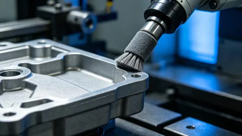
4. Compliant Abrasive Nylon Brushes for Edge Radiusing
For secondary finishing or complex 3D contours, abrasive nylon filament brushes impregnated with Silicon Carbide (SiC) or Aluminum Oxide (AO) grit (320# to 400#) are employed. Running at 1,800–3,200 RPM with low penetration depth, these flexible brushes eliminate sharp 90-degree edges, creating a controlled, uniform edge radius (0.1 mm–0.25 mm) ideal for subsequent electroplating or liquid painting.
Process Parameter Matrix: Zinc Alloy Deburring Strategies
The matrix below outlines recommended operating parameters established across successfully deployed automated deburring cells:
| Target Feature / Application | Primary Deburring Tool | Spindle Speed (RPM) | Target Contact Force (N) | Feed Rate (mm/min) | Expected Tool Life (Parts) |
|---|---|---|---|---|---|
| Heavy Parting Line & Gate Vestige | Cross-Cut Polished Carbide Burr (6–10mm) | 15,000 – 20,000 | 5.0 N – 8.0 N | 800 – 1,500 | 2,000 – 4,000 |
| Thin-Walled Edge & Fine Flash | Pneumatic Floating Carbide Insert Tool | 12,000 – 16,000 | 3.0 N – 5.0 N | 1,200 – 2,000 | 3,500 – 6,000 |
| Internal Bore & Threaded Holes | Flexible SiC Abrasive Nylon Brush (320#) | 2,000 – 3,200 | 2.0 N – 4.0 N | 1,000 – 1,800 | 5,000 – 10,000 |
| Sanitary Hardware (Pre-Plating) | Cotton / Non-Woven Blending Wheel + Brush | 1,800 – 2,500 | 3.0 N – 6.0 N | 600 – 1,200 | 1,500 – 3,000 |
Industrial Case Studies & Component Strategies
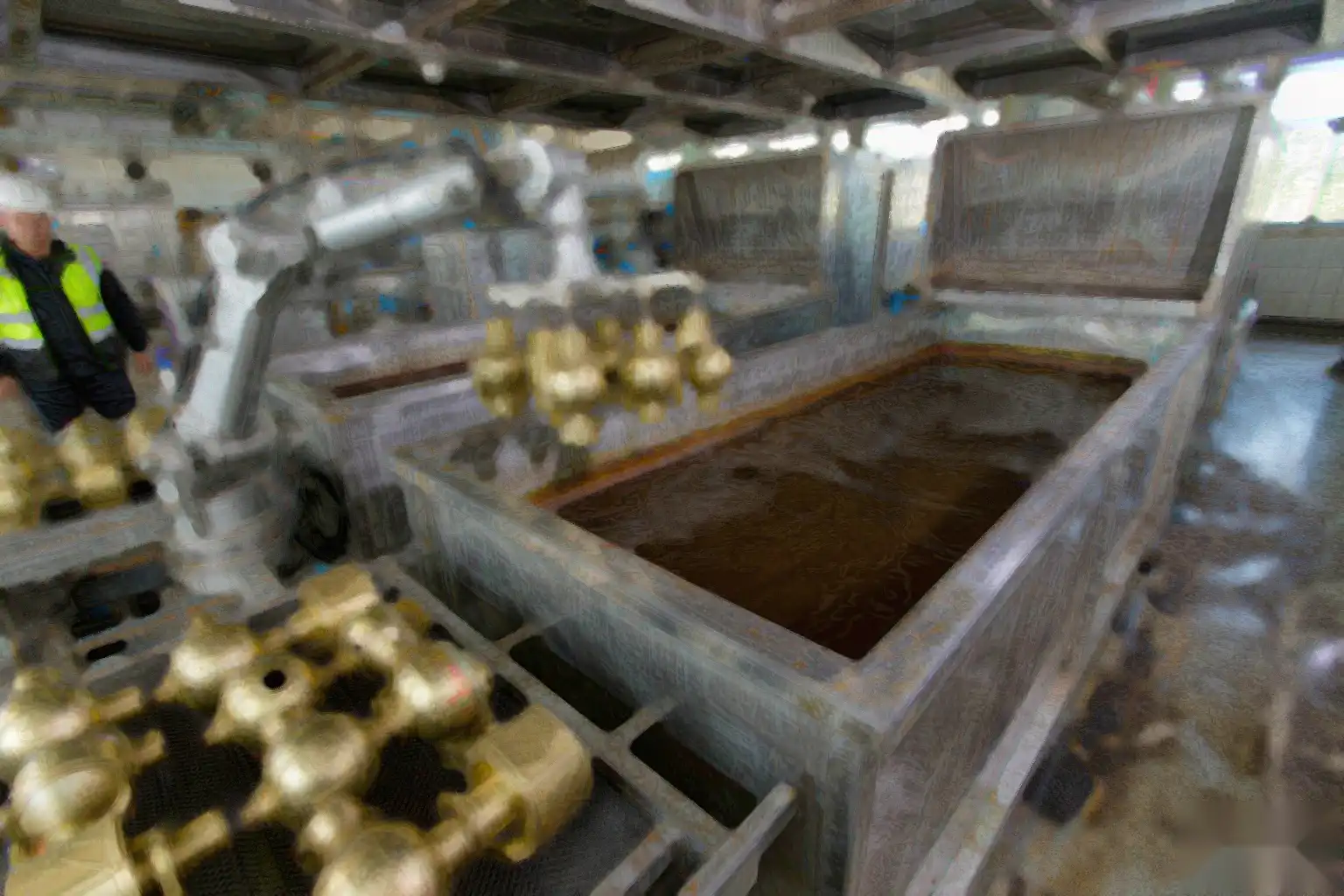
1. Faucets and Bathroom Sanitary Hardware
Zinc die-cast handles, spouts, and escutcheons demand pristine cosmetic surfaces before electroplating (chrome, satin nickel, or PVD). Any gouge or unremoved micro-burr will be magnified after plating.
Solution Strategy: A 6-axis robot utilizes a dual-tool setup. First, a floating pneumatic spindle with a polished carbide burr removes the perimeter die parting line. Second, an abrasive nylon brush sweeps over curved profiles to produce a soft blended edge. Achieved Cycle Time: 22 seconds per part; scrap rate reduced from 4.8% to 0.2%.
2. Automotive Interior Trim and Lock Components
Automotive zinc components feature tight geometric tolerances and numerous cored holes that must be completely free of loose flash to prevent functional failure in lock mechanisms.
Solution Strategy: Automated cell with quick-change tooling. The robot executes high-speed carbide deburring along external seams, followed by vision-guided inspection to verify hole cleanliness and force-log data recording for 100% quality traceability.
Engineering Troubleshooting: Solving Common Deburring Defect Issues
- Symptom: Zinc Smearing and Built-Up Edge (BUE) on Tool
- Cause: Excessive frictional heat generated during cutting, causing zinc to melt into flute valleys.
Correction: Apply an automated vegetable-based MQL (Minimum Quantity Lubrication) mist directly to the cutter. Ensure carbide burrs feature mirror-polished flutes. Increase robot feed rate by 15–25% to minimize localized dwell time. - Symptom: Surface Gouging along Parting Line
- Cause: Contact force is set too high, or the floating head has reached its mechanical stroke limit.
Correction: Decrease target pneumatic compliance pressure by 1.5–2.0 N. Recalibrate the Tool Center Point (TCP) and adjust the robot trajectory to ensure the tool stays within the mid-range of its floating stroke capability. - Symptom: Burr Fold-Over (Tearing rather than Cutting)
- Cause: Tool rake angle is too neutral or cutting speed is insufficient.
Correction: Increase spindle RPM to 18,000+. Replace standard burrs with a dedicated non-ferrous carbide geometry featuring an 8°–12° positive rake angle.
Recommended Turnkey Cell Architecture & Estimated ROI
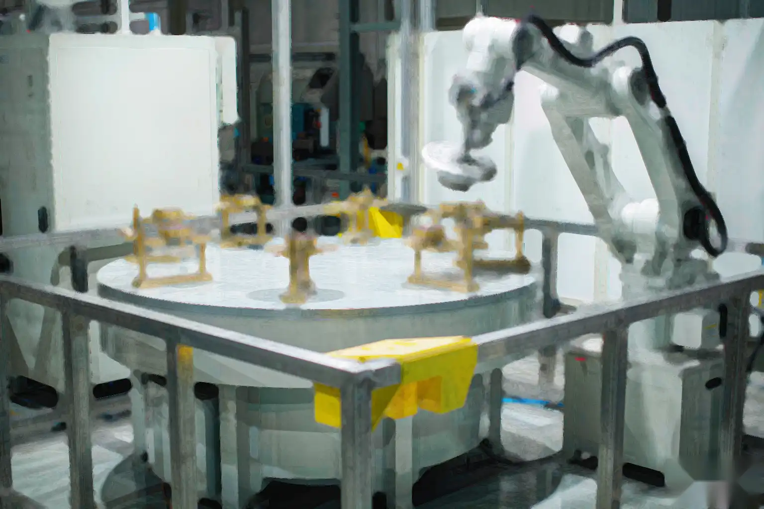
For foundries seeking to integrate automated zinc alloy finishing, DZ SMART MANUFACTURING recommends a standardized cell architecture designed for high availability and quick payback:
- Industrial Robot: Compact 6-axis articulated robot (6 kg–10 kg payload, IP67 protection rating for dusty environments).
- Spindle System: High-precision 1.0 kW electric spindle with ISO20/HSK quick-change interface (12,000–24,000 RPM).
- Compliance Unit: Dual-axis (radial/axial) pneumatic floating force mechanism with digital regulator.
- Dust Extraction: Explosive-proof wet dust collector (zinc dust presents explosive characteristics under NFPA/ATEX guidelines).
- Safety Enclosure: Interlocked safety cell with light curtains and integrated Safety PLC.
Investment & Return on Investment (ROI):
A turnkey automated zinc deburring cell typically requires an investment ranging between USD $38,000 and $68,000. For operations processing 1,000+ castings daily across two shifts, labor replacement, reduced consumable wear, and scrap reduction yield a full financial ROI in 10 to 14 months.
Frequently Asked Questions (FAQ)
Q1: Can zinc alloy die castings be deburred dry without cutting fluids?
Yes. Dry deburring is widely preferred to prevent downstream cleaning steps prior to powder coating or plating. However, dry processing strictly requires mirror-polished, uncoated carbide tools or PCD cutters, combined with optimized feed rates to prevent thermal smearing.
Q2: How does automated deburring handle dimensional variations from cast-to-cast?
Automated systems utilize mechanical floating heads (pneumatic/spring compliance) or real-time force sensor feedback. This enables the tool to dynamically float up to ±3 mm, maintaining constant contact force regardless of part dimensional drift.
Q3: What safety measures are critical for zinc deburring cells?
Fine zinc dust generated during high-speed deburring can be combustible. Automated cells must be equipped with dedicated wet-scrubber dust collectors, grounded conductive ductwork, and explosion-proof cell ventilation following local industrial safety directives.