A bad mold design will punish every KPI that follows: cycle time, scrap rate, dimensional capability, surface finish, and mold life. A good mold design will quietly deliver acceptable performance across all five even when the foundry is average. The difference between a 200,000-shot mold and a 500,000-shot mold usually comes down to four decisions: tool steel choice, gate and runner layout, cooling channel layout, and ejection design.
This guide walks through each of those decisions in plain language, with the rationale a die casting buyer or process engineer needs to evaluate a mold drawing. The recommendations reflect what high-volume foundries in China, India, Turkey, and Mexico practice on parts above 100 g and below 5 kg, which is the bulk of structural and decorative aluminum die castings.
Tool Steel Selection
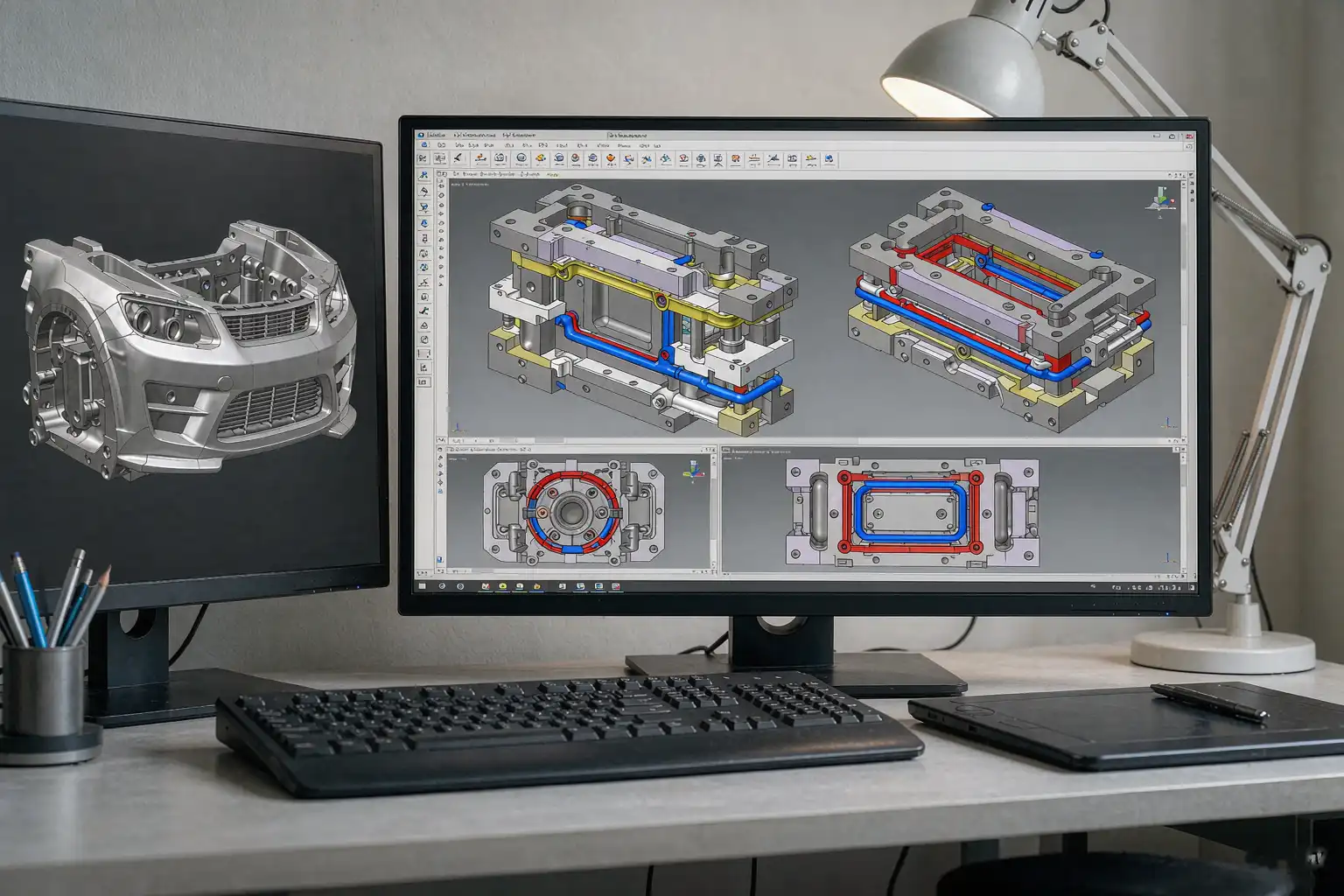
Tool steel choice balances three variables: hardness, toughness, and cost.
| Steel | Hardness (HRC) | Toughness | Cost (relative) | Typical use |
|---|---|---|---|---|
| H13 | 48 to 52 | Good | Medium | Inserts, cores, slides for general aluminum |
| SKD61 (Japanese equivalent) | 48 to 52 | Good | Medium | Same as H13, premium Asian foundries |
| DIN 1.2344 (European) | 48 to 52 | Good | Medium | Same as H13, premium European foundries |
| H11 | 38 to 44 | Very good | Medium | Slides and lifters where impact is high |
| H21 | 50 to 55 | Low | High | Wear-critical areas, short runs |
| S7 | 50 to 55 | Good | High | High-impact slides, ejector pins |
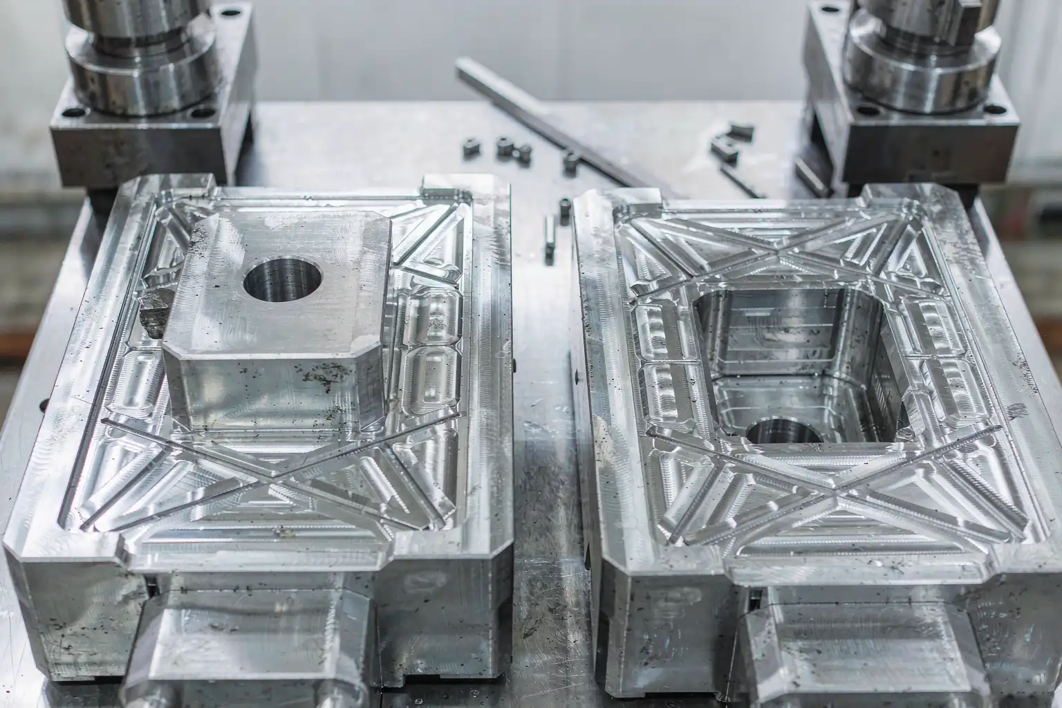
For the vast majority of aluminum die castings, H13 (or its regional equivalents SKD61 / 1.2344) is the right choice for cavity and core inserts. H13 hardens to 48 to 52 HRC, takes a good texture for shot blasting or EDM, and resists heat checking on long runs.
The most common mistake is using H13 for everything. Slides, lifters, and ejector pins that see heavy impact should be H11 or S7 for toughness. The most expensive mistake is using H11 or S7 for the cavity because heat checking then sets in at 30,000 shots and the mold is dead by 60,000.
For high-volume structural parts (above 100,000 shots), premium H13 with double vacuum heat treatment extends mold life significantly. The premium is roughly 15 to 25 percent on the steel, but the gain is 50 to 100 percent on mold life.
Gate and Runner Design
The gate and runner system does two jobs: fill the cavity without cold shuts, and release the part without distortion. Most aluminum die castings use a tab gate or a fan gate for cosmetic parts, and a direct gate or a pinpoint gate for structural parts.
Gate type by part type
- Decorative or cosmetic parts — fan gate at a thick boss, or tab gate on a flange. Fan gates spread the metal evenly and reduce flow lines on Class A surfaces.
- Structural parts — direct gate at the heaviest section. Direct gates minimize flow length and reduce porosity. The gate scar is ugly, so it must land on a non-show surface or be machined off in a secondary operation.
- Thin-wall parts — multiple tab gates or a hot runner system. Hot runners cut cycle time by 10 to 20 percent and reduce scrap by eliminating the runner itself, which on long runners can be 20 to 40 percent of the shot weight.
Runner sizing
A common rule of thumb: keep the runner cross-section between 60 and 80 percent of the gate thickness. Too thick and the runner freezes after the cavity fills, locking in pressure. Too thin and the runner freezes before the cavity fills, causing cold shuts.
For a typical aluminum part with a 2 to 3 mm wall, the gate thickness should be 1.5 to 2.5 mm and the gate width 6 to 12 mm. Run the flow analysis before quoting. If the foundry does not run flow analysis before quoting the mold, the quote is a guess.
Cooling Channel Layout
Cooling is where most aluminum die casting molds underperform. A well-cooled mold runs 20 to 30 percent faster cycle time, lasts 30 to 50 percent longer, and produces parts with tighter dimensional capability. A poorly cooled mold runs hot in some spots and cold in others, causing heat checking, solder, and uneven ejection.
The principles
- Cool every cavity face. Every face that sees direct metal contact needs a cooling channel within 15 to 25 mm of the cavity surface. Channels further away create hot spots that warp the mold and shorten life.
- Cool inserts from inside. Inserts that form bosses, ribs, or features must have their own cooling channels or beryllium copper cores. A boss without internal cooling becomes the hot spot that cracks first.
- Balance the cooling water flow. Water enters at one end and exits at the other. Use baffled channels or cross-drilled baffles to ensure turbulent flow (Reynolds above 10,000). Laminar flow does not transfer heat.
- Separate hot and cold zones. The area near the gate is hotter than the far end of the cavity. Use a separate cooling circuit for each zone, with different flow rates. The hot zone needs more flow, not less.
- Use beryllium copper at hot spots. Where steel cooling cannot keep up, a beryllium copper insert pulls heat five to ten times faster. The cost is 3 to 5 times the steel equivalent and the wear life is shorter, so use it sparingly.
A mold that follows these five principles will run 1.5x to 2x the cycles of a mold that ignores them. The cost difference on the mold is 5 to 15 percent.
Ejection Design
Ejection is the second most common source of mold failure after cooling. The most common mistakes:
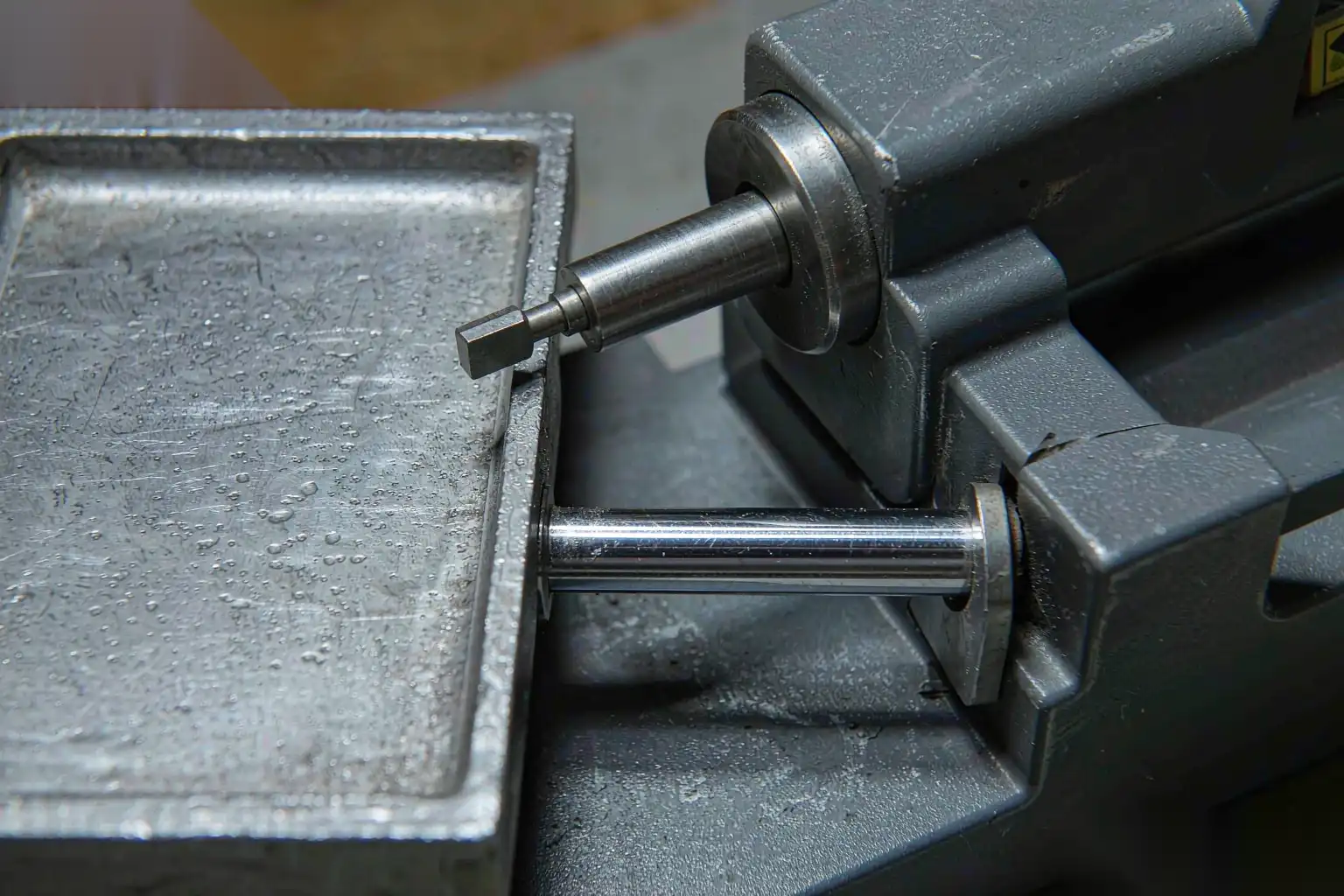
- Ejector pins too small. Ejector pins under 6 mm on aluminum will gall and break. Use 8 to 12 mm pins for primary ejection and 6 mm pins only for cosmetic pin marks in non-show areas.
- Ejector pins in show surfaces. Pin marks on Class A surfaces are an automatic reject at most buyers. Put pins on the back side, on ribs, or on flanges, never on visible faces.
- No sleeve ejection for cylinders. Cylindrical cores need a sleeve ejector, not a pin. A pin on a cylinder wall leaves a deep mark that traps air and causes porosity.
- No undercuts planned. Undercuts must be on slides or lifters, with clearance for the slide action and wear compensation. Trying to “snap out” an undercut on ejection is a short path to mold damage.
- No ejection on the heavy side. The part should eject off the heavy side first, then the light side. Reverse this and the part warps or the pins bend.
A well-designed ejection system is invisible on the part, lasts the full mold life, and runs without operator intervention.
Slides and Lifters
Slides and lifters form the undercuts that define the geometry of most aluminum die castings. Common mistakes:
- Slide angles under 5 degrees. Slides need at least 5 degrees of draft to release cleanly. Less than that and the slide jams within the first 10,000 shots.
- No wear compensation. Slides need adjustable wear plates. A slide without adjustment wears into the cavity within 50,000 shots and the part dimensions drift.
- Lifter angles under 5 degrees. Same rule as slides, applied to lifters.
- No cooling on slides. Hot slides wear faster and weld to the cavity. Run a cooling line through every slide that sees more than 5 seconds of contact.
A four-slide mold with proper cooling, wear plates, and lifter cooling will run 150,000 shots without slide-related maintenance. A four-slide mold without those features will need slide repair at 30,000 shots.
Mold Life Expectations
For H13 (or equivalent) inserts on aluminum die casting:
| Part complexity | Expected life (shots) |
| Simple two-plate decorative part | 150,000 to 300,000 |
| Three-plate structural part | 80,000 to 150,000 |
| Four-slide part with cores | 50,000 to 100,000 |
| Complex multi-slide structural part | 30,000 to 60,000 |
These numbers assume proper cooling, ejection, and maintenance. Without them, halve the numbers.
How DZ Smart Manufacturing Approaches Mold Design
DZ Smart Manufacturing designs and builds molds in-house for the parts we cast, and we partner with vetted mold makers for the rest. The four decisions above (steel, gates, cooling, ejection) are non-negotiable on every mold we approve. We have seen too many buyers save 10 percent on the mold and lose 30 percent on the part cost over the program life.
If you are evaluating a mold drawing or quoting a new part, contact DZ for a mold design review. We will check the four decisions above and give you a written assessment in 48 hours.
Author: Mr. Lai Dingren, General Manager, DZ Smart Manufacturing. 20+ years in die casting tooling. LinkedIn: linkedin.com/in/dzivy
About this article: Educational content. The recommendations are typical industry practice. Always validate with your own mold flow analysis before issuing a tooling check. The four design decisions covered above are the floor, not the ceiling. Programs that succeed over hundreds of thousands of shots always come back to the same principles: pick the right steel, run the flow analysis before cutting steel, design the cooling channels from the cavity surface inward, and put the ejector pins where the operator cannot see them.
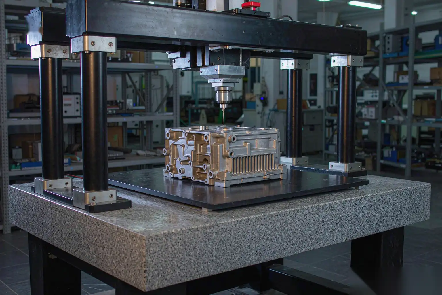
For plants running an existing mold that is underperforming on cycle time or reject rate, the fastest wins are almost always in the cooling circuit. Re-cut or add beryllium copper inserts at the hot spots before doing anything else. The second fastest wins are in the gate location, which can sometimes be opened up or shifted with a weld repair during a planned tool stop. Only after cooling and gating should a toolmaker touch the ejector system, and only then with the part on a CMM to confirm the cause of the failure rather than guess.