Aluminum Die Casting for Lighting Parts: Heat Sinks, Housings, and Heat Management
Why Aluminum Die Casting Dominates Lighting Hardware
Modern lighting — particularly LED-based — has three structural requirements that align almost perfectly with die cast aluminum:
- Heat dissipation. LEDs convert 30-40% of input power into light and the rest into heat. Junction temperature is the limiting factor for LED lifetime: a 10°C increase in junction temperature roughly halves the LED lifetime. Aluminum die castings provide the thermal mass and surface area to keep junction temperatures within spec.
- Lightweight structural support. Die cast aluminum delivers the rigidity of steel at one-third the weight, important for downlights, track lights, and architectural fixtures where the ceiling structure cannot carry heavy loads.
- Aesthetic finish. Die cast aluminum accepts a wide range of finishes — anodized, powder coated, polished, brushed — and is perceived as a premium material by lighting specifiers and end users.
The global market for die cast aluminum lighting components is roughly $4-5 billion and growing at 5-7% annually, driven by the LED transition in commercial, industrial, and architectural lighting.
Common Lighting Parts Made by Die Casting

The most common die cast aluminum lighting parts:
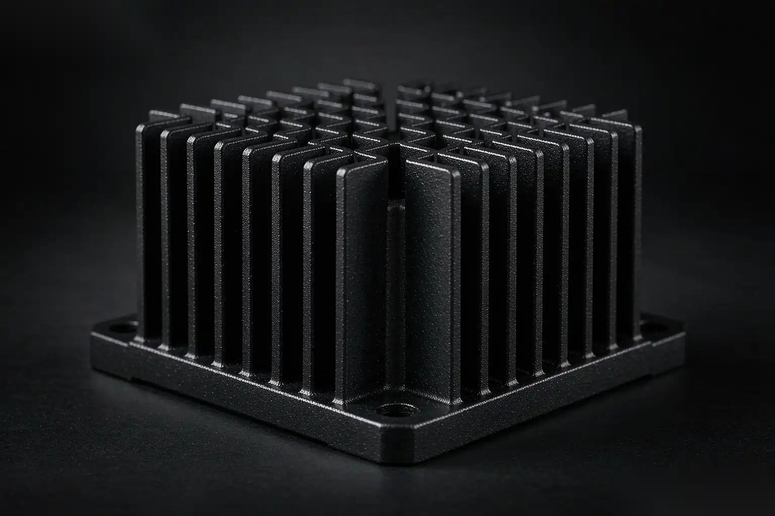
- LED heat sinks for downlights, track lights, street lights, high-bay fixtures
- Luminaire housings for outdoor floodlights, wall packs, canopy lights
- Driver enclosures for indoor and outdoor fixtures
- Reflector bodies for spotlights and accent lighting (often polished internally)
- Mounting yokes and trunnions for adjustable fixtures
- Heat sink + housing integrated parts (the most common modern design)
- Heat pipe mounting plates for high-power industrial LED fixtures
- Bezels and trim rings for architectural downlights
The integrated heat sink + housing design is increasingly dominant because it eliminates thermal interface material (TIM) between the LED and the heat sink, improving thermal performance by 15-30%.
Heat Sink Design Rules for Die Cast Aluminum
Heat sink performance is governed by thermal resistance: the lower, the better. For a die cast heat sink, thermal resistance depends on:
- Total surface area (fins, base, mounting surfaces)
- Fin density and geometry (height, thickness, spacing)
- Material thermal conductivity
- Convective environment (forced air vs natural convection)
- Interface to the LED (direct mount, thermal pad, thermal paste)
For die cast aluminum heat sinks, the design rules are:
- Optimize fin height over fin density. In natural convection, taller fins outperform more numerous short fins. A typical rule: 1.5-2.0x fin height over thickness. So 25 mm tall fins should be 1.5-2.0 mm thick.
- Use the maximum fin spacing that maintains structural integrity. 8-12 mm spacing is typical for natural convection. Forced air can use 5-7 mm spacing.
- Avoid solid bases thicker than 5-6 mm. The base only needs to be thick enough to spread heat from the LED mount to the fins. A thicker base adds cost and weight without thermal benefit.
- Specify A380 or A384 alloy. Both have thermal conductivity of 96-110 W/m·K in the die cast condition. Higher-copper alloys (A390) are not used for heat sinks — copper reduces thermal conductivity.
- Surface treatment affects thermal performance. Anodizing adds a thin ceramic layer with lower thermal conductivity than aluminum. Black anodizing is the standard for heat sinks because the high emissivity (0.85-0.95) helps radiative heat transfer, partially offsetting the conduction loss through the anodized layer.
- Draft angles on fin tips are non-negotiable. Without 1-3° draft, fins drag on the die and either break or come out warped. A warped fin is worse than a missing fin for thermal performance.
Thermal Modeling — Predicting Performance Before Tooling
Before cutting steel for the die, build a thermal model of the proposed heat sink design. The standard approach:
- Steady-state CFD or analytical model of the heat sink at the worst-case operating condition (highest ambient temperature, maximum LED drive current, end-of-life LED forward voltage).
- Calculate junction temperature using LED manufacturer’s thermal resistance from junction to case (Rj-c), thermal interface material resistance (R-tim), heat sink to ambient resistance (Rsa).
- Compare to LED maximum junction temperature (typically 120-150°C depending on the LED package). Design with 20°C margin.
A common rule of thumb for die cast aluminum heat sinks: for a 50W LED fixture in natural convection, you need 600-1,000 cm² of fin surface area to keep junction temperature below 100°C at 35°C ambient. For forced air or liquid cooling, the surface area requirement drops dramatically.
IP Ratings and Die Cast Lighting Enclosures
Outdoor lighting requires ingress protection (IP) ratings. The most common:
- IP54: dust-protected, splash-resistant. Achievable with a die cast housing and silicone gasket at the cover seam.
- IP65: dust-tight, water jet resistant. Requires careful gasket design, cable gland sealing, and a drain path for any condensation.
- IP66: dust-tight, powerful water jet resistant. Requires a more robust gasket and proven drainage.
- IP67: immersion to 1m for 30 minutes. Requires sealed cable entries and a vent (typically ePTFE membrane) to manage internal pressure cycling.
Die cast aluminum is well-suited to IP65 and IP66 ratings because the die cast surface is dimensionally stable and provides a good sealing surface. For IP67, additional testing and possibly a vent are required.
Surface Finishing for Die Cast Lighting Parts
The choice of finish affects both aesthetics and thermal performance:
- Raw as-cast (bead blasted): low cost, good for industrial fixtures where the housing is not visible. Thermal performance is best because there is no surface layer.
- Black anodizing (Type II): the standard for heat sinks. Adds 5-15 µm of aluminum oxide with high emissivity. Thermal resistance increases by 5-10% but radiative cooling helps offset this.
- Powder coating: the standard for outdoor architectural fixtures. Provides color choice, UV resistance, and corrosion protection. Thermal resistance increases by 10-20% compared to raw, so it is rarely used on heat sink surfaces.
- Polishing + clear coat: premium indoor fixtures, reflectors. Polishing is labor-intensive and adds cost. Best done on a separate reflector part that mounts to the heat sink.
- Brushed nickel or chrome appearance: achieved through powder coating with metallic pigments, not actual plating. Used for premium indoor fixtures.
For an integrated heat sink + housing design, a common pattern is to leave the external heat sink fins raw (bead blasted) and powder coat only the housing body and trim.
Common Failure Modes in Die Cast Lighting Parts
In our experience, the most common reasons die cast aluminum lighting parts fail:
- Insufficient fin draft. 0.5° draft instead of 1.5°+. Fins come out warped, reducing surface area and creating hot spots.
- Wrong alloy for thermal performance. A390 or other high-copper alloys used for heat sinks because of perceived “strength” — actually reduces thermal conductivity.
- Powder coating over heat sink surfaces. Adds thermal resistance and reduces effective heat dissipation. Specify bare heat sink surfaces.
- Inadequate gasket design. Compression stops missing, gasket creep not considered, no drainage path. Water ingress destroys LEDs and drivers.
- Thermal interface material not specified. A poor or missing TIM can add 0.5-1.0°C/W to the thermal path, raising junction temperature 10-20°C.
- Surface treatment peeling. Caused by inadequate pre-treatment, contamination, or excessive coating thickness. Compromises both appearance and corrosion protection.
These are all preventable with proper design review before tooling.
Cost Drivers for Die Cast Lighting Parts
For a typical die cast aluminum heat sink or housing, the cost structure is:
- Material (alloy): 25-35% of cost.
- Casting (machine + labor + overhead): 30-40%.
- Finishing (anodize, powder coat, polish): 20-35% — a larger share than for most industrial die castings because lighting is finish-driven.
- Quality + inspection: 5-10%.
- Packaging + logistics: 3-5%.
Tooling is a separate upfront cost, amortized over the production volume. A typical 4-cavity die for a heat sink costs $25,000-$60,000 from a Chinese supplier, $60,000-$150,000 from a Western supplier.
Design Validation — What to Test Before Mass Production
Before approving a die cast lighting part for mass production, run these validation tests:
- Dimensional CMM report on T1 samples, including critical LED mounting surfaces and gasket grooves.
- Thermal performance test at worst-case operating conditions, measuring junction temperature with calibrated thermocouples.
- IP rating test per IEC 60529, performed by an accredited lab for outdoor fixtures.
- Salt spray test per ASTM B117 for outdoor fixtures, typically 500-1000 hours exposure.
- Vibration and mechanical shock per applicable standards (UL, CE, customer-specific).
- UV exposure for outdoor fixtures with powder coat or anodized finish, per ASTM G154 or equivalent.
- Thermal cycling (-40°C to +85°C, 100+ cycles) to validate solder joint reliability on the LED PCB.
A capable supplier runs all of these. A weak supplier skips the ones that might fail.
A Practical Validation Checklist Before Tooling Release
Before releasing a die cast lighting part for tooling, run this short validation list. It takes one meeting and prevents the four most common lighting-program failures. One: thermal model at worst-case conditions, with 20°C junction margin, not typical-case math. Two: fin geometry reviewed for castability — 1.5 to 3.0 mm fin thickness, 1 to 3° draft on every fin surface, no fin spacing below 5 mm without forced air. Three: IP sealing path confirmed, including drain and pressure-equalizing vent, with the gasket groove machinable on the as-cast surface. Four: finishing plan named — anodize, powder, or paint — with the alloy checked against that finish’s color behavior.
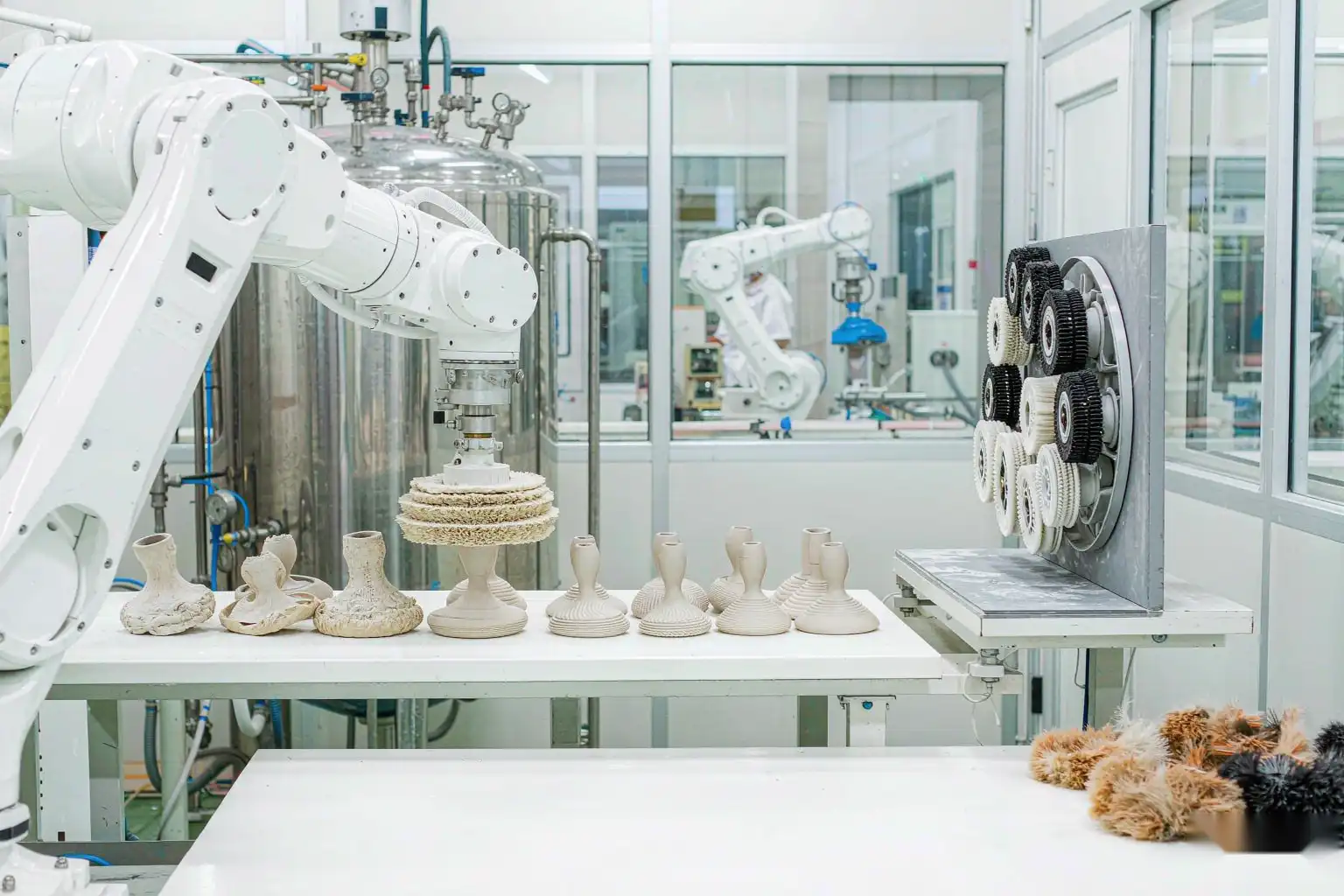
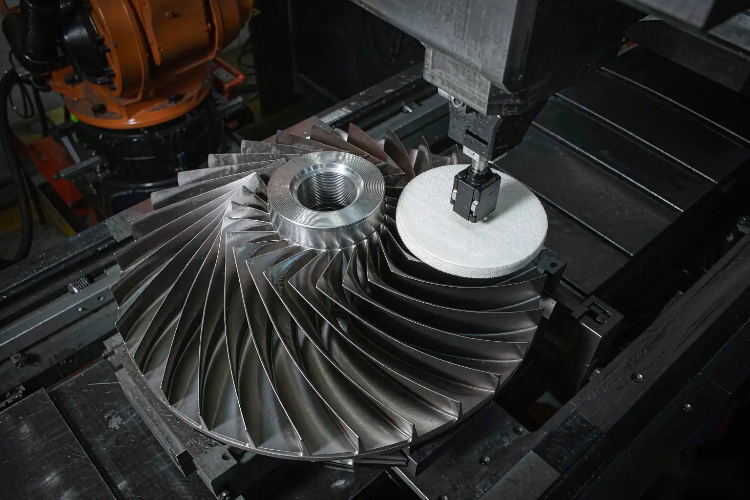
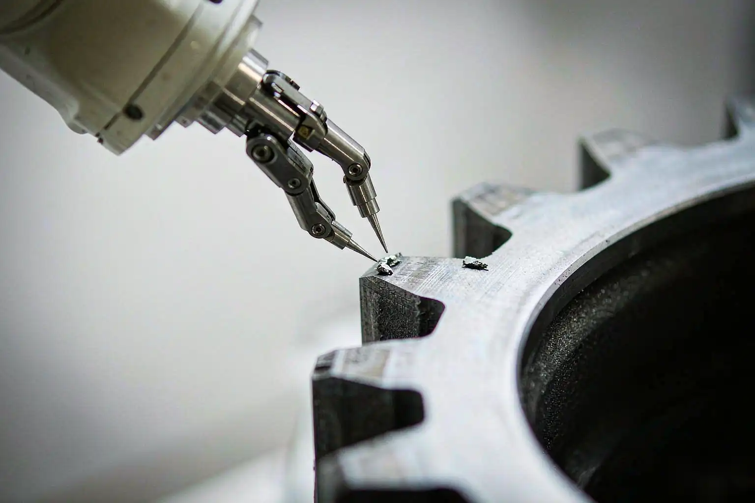
DZ Machinery supports lighting OEMs at exactly this stage. Our robotic deburring and polishing cells finish thousands of die cast heat sinks and housings daily, and the parts that flow through our cells best are the ones whose designers asked these four questions first. If you are within weeks of tooling release, send us the drawing; we will return a finishing feasibility read with realistic cycle time and surface-finish expectations.
FAQ About Aluminum Die Casting for Lighting Parts
What alloy is best for die cast LED heat sinks?
A380 or A384 is the standard choice for cost-effective heat sinks. For premium applications where maximum thermal conductivity matters, specify A384 with low iron content. Avoid A390 (high copper) and A413 (lower strength) for heat sinks.
Can die cast aluminum heat sinks be used with high-power LEDs (200W+)?
Yes, but the heat sink must be substantially larger than for low-power LEDs. For 200W+ LED fixtures, forced air cooling or liquid cooling is often needed, and the die cast heat sink becomes more of a cold plate than a finned heat sink.
What surface finish gives the best thermal performance for a die cast heat sink?
Raw as-cast (bead blasted to uniform matte finish) has the best thermal performance. Black anodizing is a close second and is the practical standard because it also provides corrosion protection and a uniform appearance. Avoid powder coating on heat sink surfaces.
How long does it take to tool a die cast aluminum lighting part?
For a typical heat sink or housing, plan 6-10 weeks: 1-2 weeks for DFM and tool design, 4-6 weeks for die fabrication, 1-2 weeks for sampling and T1 approval. Add 2-3 weeks if finishing (anodizing, powder coating) is set up at a different facility.
Bringing It Together
Die cast aluminum is the right answer for most lighting hardware because of its thermal performance, weight, finishability, and cost. But the design rules are specific — fin draft, alloy choice, surface treatment, and gasket design all have to be right.
At DZ Smart Manufacturing, our robotic polishing and finishing cells handle die cast aluminum lighting parts at scale — bead blasting, polishing, and surface preparation for downstream anodizing or powder coating. If you are evaluating a new die cast lighting part and want feedback on the finishing scope, or if you are struggling with inconsistency in your current finishing line, our engineering team can review your drawings and suggest process improvements.