Aluminum Die Casting Corrosion Protection: What Actually Fails and What Works
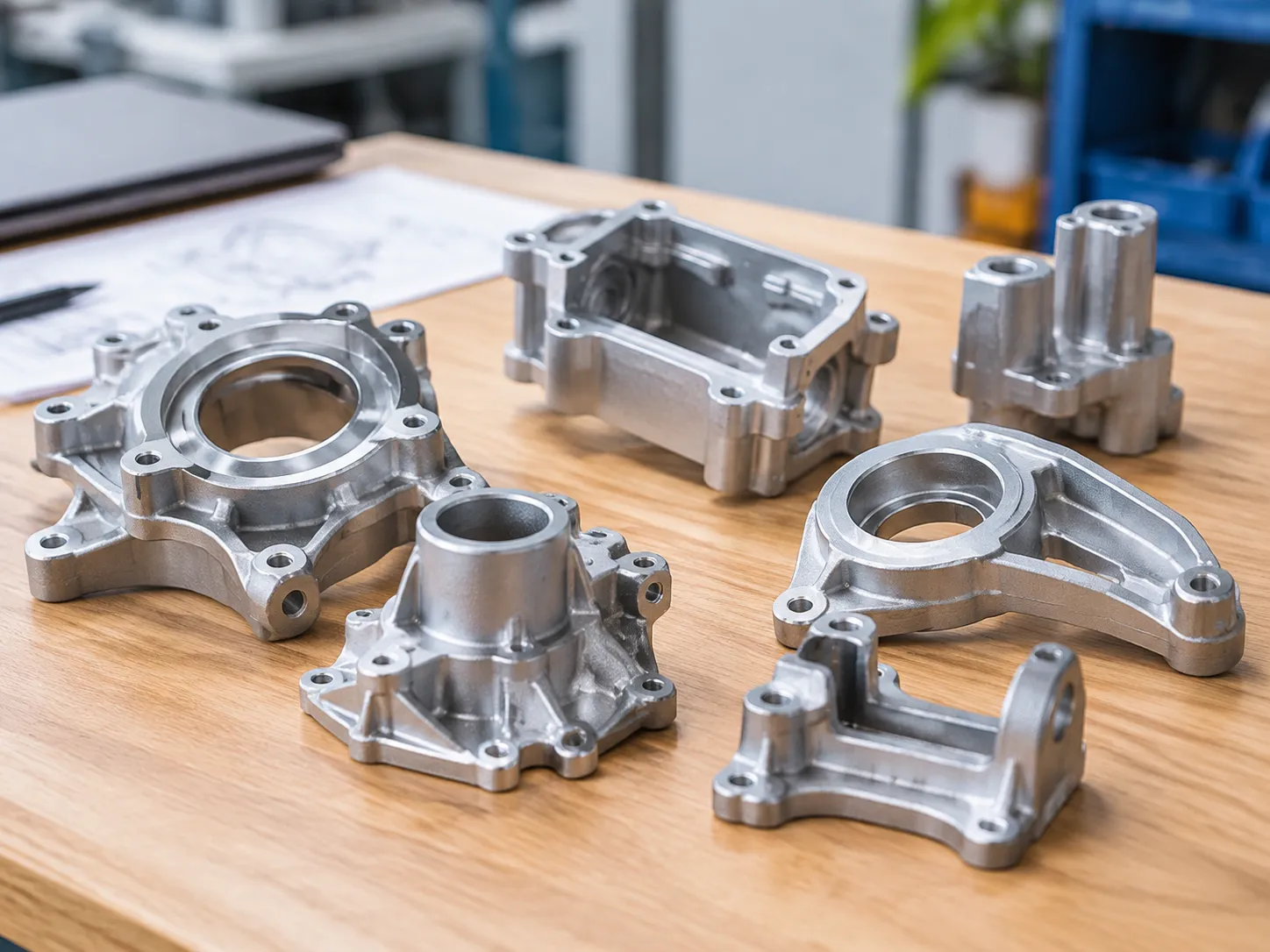
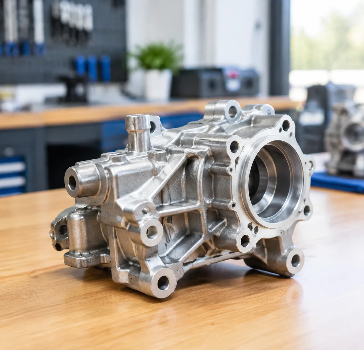
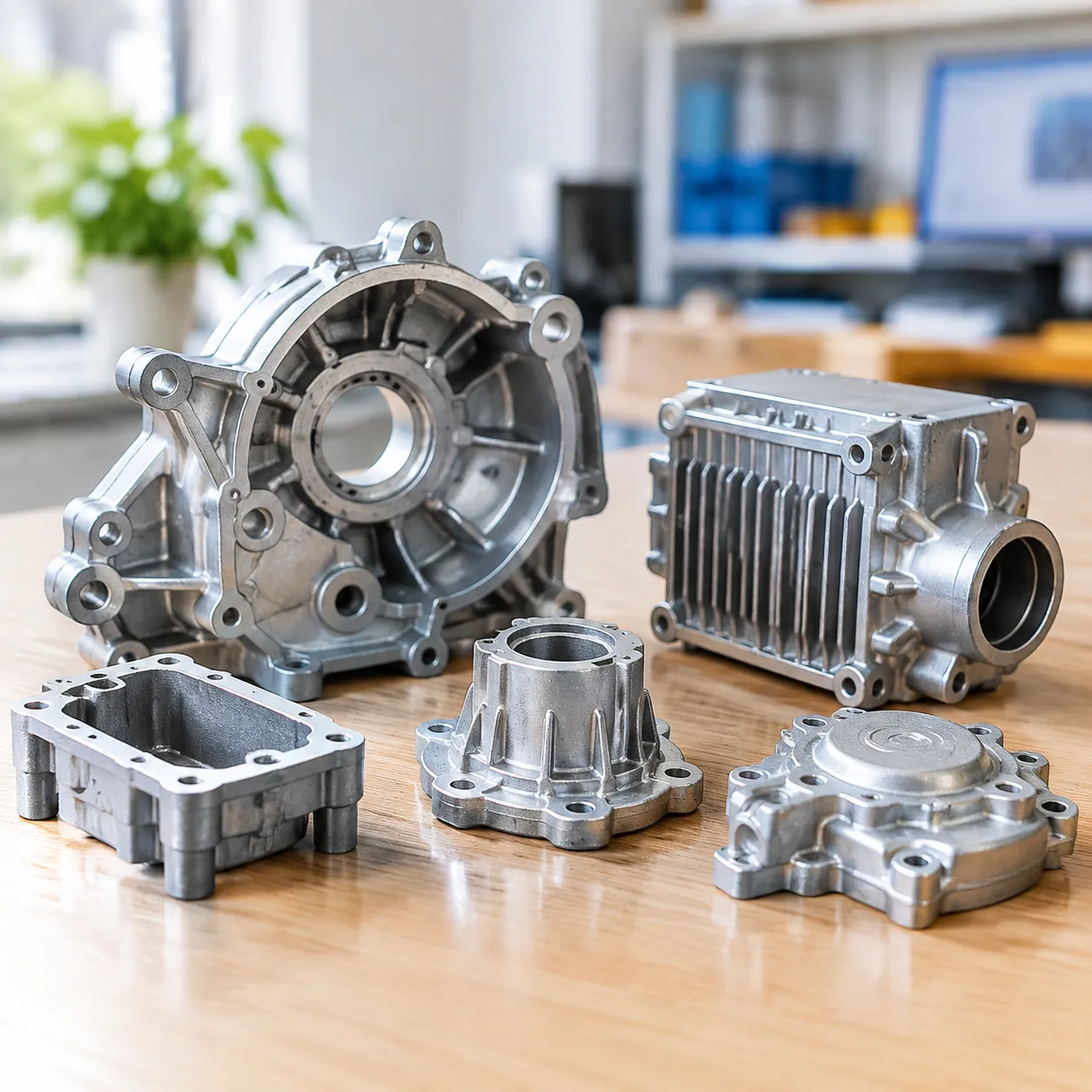
Aluminum is described as corrosion resistant because it forms a passive oxide film. That is true of a wrought 6060 extrusion with a clean surface. It is only partly true of a high-pressure die casting, and the gap between the two is the reason so many coated castings come back from the field with blisters around a boss or white rust blooming out of a blind hole.
The difference is metallurgy and geometry. A die casting is a two-phase microstructure full of intermetallic particles, it contains porosity, and its surface carries whatever the release agent left behind. Understanding those three things tells you which protection route will survive and which will fail in the first winter.
Why die castings corrode
A cast aluminum-silicon alloy is not a uniform solid. It is a primary aluminum-rich phase with eutectic silicon, plus intermetallic particles that form during solidification, and each of those constituents has a different electrochemical potential. Corrosion in aluminum is almost always local, driven by those potential differences.
The mechanisms that matter in practice:
- Copper-rich phases. Alloys in the A380 / ADC12 family carry 3-4% copper deliberately, for strength and castability. Copper in solution and as Al₂Cu intermetallics is cathodic to the aluminum matrix. In the presence of an electrolyte, the aluminum around the particle dissolves. This is why high-copper die casting alloys are noticeably less corrosion resistant than low-copper ones, and why they are a poor substrate for decorative anodizing.
- Iron-rich intermetallics. Iron is unavoidable in die casting; it is picked up from the crucible and the die, and levels around 0.8-1.3% are actually maintained deliberately to reduce die soldering. The needle and platelet Al-Fe-Si phases that result are also cathodic and act as local initiation sites.
- Silicon particles. Eutectic silicon itself is cathodic relative to the matrix and, in a coarse or unmodified structure, creates a large area of interface where attack can start. It also makes anodizing difficult, because silicon does not anodize the way aluminum does, so the film grows non-uniformly and appears dark and mottled.
- Porosity as a transport path. Gas and shrinkage porosity connect the surface to the interior. An electrolyte that enters a pore does not dry out, and a pore that opens into the surface after machining becomes a crevice. This is the single most common origin of blistering under an organic coating.
- Residual flux and dross inclusions. Chloride and fluoride salts from fluxing are hygroscopic and aggressive. An inclusion that intersects the surface will start a pit regardless of how good the coating is.
- Release agent residue. Water-based release agents leave a film that, if not removed, prevents conversion coating and paint adhesion. It also traps chlorides in some formulations.
- Galvanic coupling in assembly. Aluminum is anodic to stainless steel, copper and brass. A casting bolted to a steel bracket will corrode, and the smaller the aluminum area relative to the cathodic area, the faster.
Salt spray expectations by alloy and finish
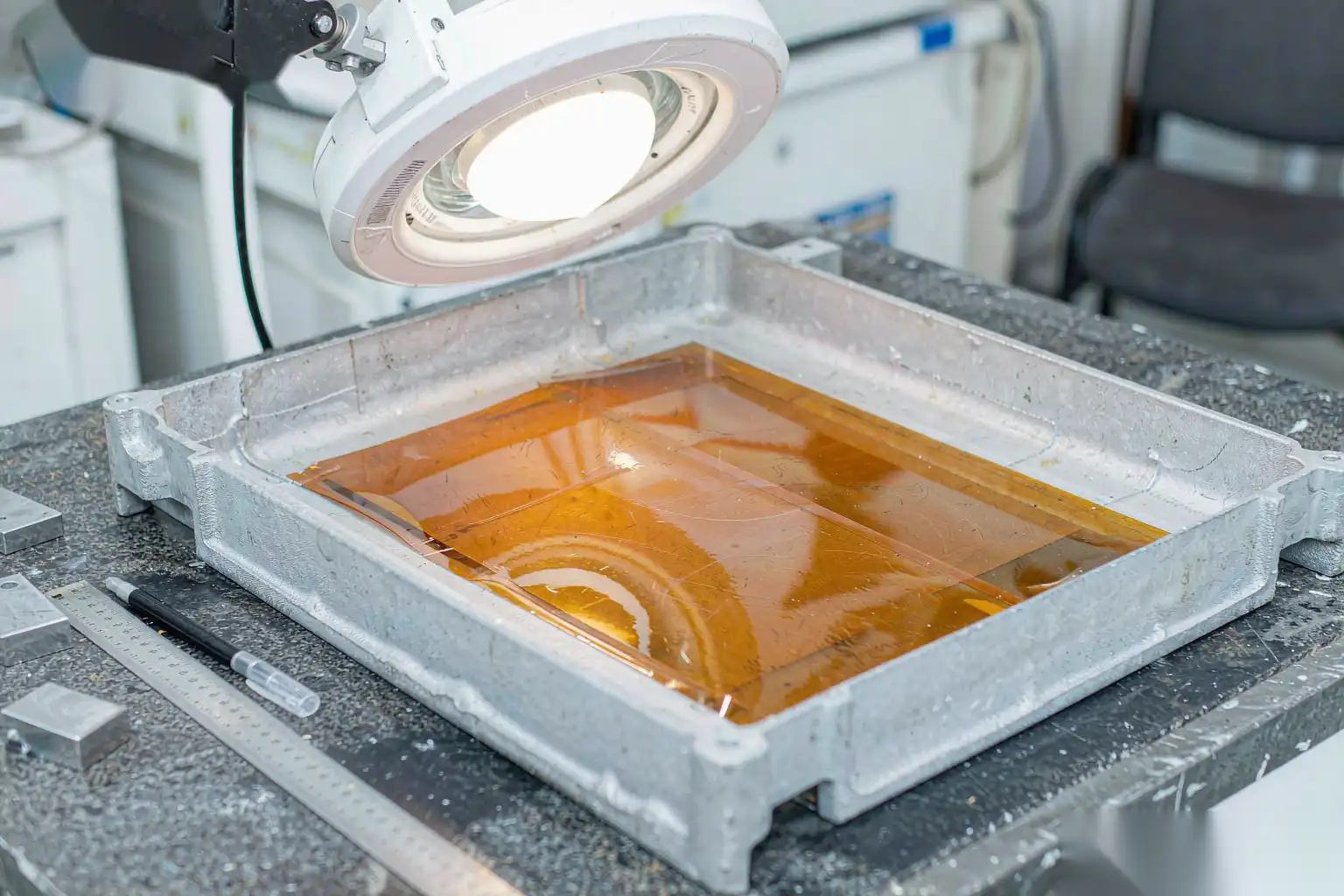
Neutral salt spray per ASTM B117 is a comparative test, not a service-life predictor, but it is the common currency in specifications. These are realistic ranges for uncoated and coated material, understood as hours to the first appearance of the stated defect.
| Alloy / condition | Bare, as-cast | Chromate conversion | Anodized, sealed | Powder coat | E-coat |
|---|---|---|---|---|---|
| A380 / ADC12 (Cu 3-4%) | 24-100 h to white rust | 168-336 h | Not recommended; dark, mottled | 500-1000 h | 750-1000 h+ |
| A360 / AlSi10Mg (low Cu) | 100-300 h | 336-500 h | 300-600 h | 750-1000 h | 1000 h+ |
| A413 / AlSi12 (low Cu, high Si) | 100-250 h | 336-500 h | Difficult, grey | 750-1000 h | 1000 h+ |
| Low-pressure cast AlSi7Mg, T6 | 150-400 h | 336-500 h | 400-800 h | 750-1000 h | 1000 h+ |
Two caveats on reading this table. First, the ranges are wide because substrate preparation dominates the result: the same alloy and the same coating can differ by a factor of three depending on whether the pre-treatment line was controlled. Second, salt spray correlates poorly with real outdoor exposure for organic coatings. A cyclic test with wet, dry and salt phases will rank coatings much closer to field behaviour than continuous fog does.
Protection routes compared
Each route has a characteristic failure mode and a cost structure. The table below is the comparison we use when a customer is choosing.
| Route | Typical thickness | Salt spray, realistic | Substrate sensitivity | Relative cost | Best for | Characteristic failure |
|---|---|---|---|---|---|---|
| Chromate / chromium-free conversion | 0.2-1.0 µm | 168-500 h | Medium; needs clean, oxide-free surface | Low | Paint base, indoor parts, electrical enclosures | Thin film offers no barrier; abrasion kills it |
| Sulfuric anodize, Type II, sealed | 5-25 µm | 300-800 h on low-Cu alloys | High; poor on high-Si, high-Cu die cast | Medium-high | Low-copper alloys, wear surfaces | Grey, mottled, non-uniform on A380 |
| Hard anodize, Type III | 25-75 µm | 500-1000 h, abrasion resistant | High; not practical on most HPDC | High | Wear surfaces, low-Si alloys | Cracking at sharp radii and at pores |
| Powder coat (polyester or epoxy-polyester) | 60-120 µm | 500-1000 h | High; outgassing from pores | Medium | Housings, brackets, outdoor hardware | Blistering and pinholes from porosity outgassing |
| E-coat / electrophoretic primer | 15-35 µm | 750-1000 h+ | Medium; penetrating power is better | Medium-high | Complex geometry, as a primer under powder | Thin coverage at recesses if throw is poor |
| Mechanical polish + passivation | Ra 0.05-0.4 µm, no added thickness | 96-500 h, depending on passivation | High; surface must be defect free | Medium-high, labour driven | Faucet bodies, handles, lock plates | Local pitting at exposed pores; fingerprint staining |
| Shot blast + conversion + powder | 60-120 µm total | 750-1000 h | Medium; blast closes and cleans the surface | Medium | General industrial, structural | Same as powder, plus blast media embedment |
| Impregnation + coating | Pores filled, then as above | Restores design intent | Adds a step before coating | Additive | Pressure-tight parts | Cured resin can outgas if overheated in bake |
Note on anodizing specifically: it is the first thing people ask for and the last thing that works on a standard high-pressure die casting. With 8-11% silicon and 3-4% copper, the film grows irregularly and the result is a dark grey, blotchy surface that no amount of sealing will make decorative. If an anodic appearance is mandatory, the alloy and the casting process have to change, which usually means low-pressure or gravity casting with a low-silicon, low-copper alloy. Our aluminum alloy die casting guide walks through that selection, and the surface expectations by finish are set out in die casting surface finish standards.
Note on porosity and organic coatings: a powder coat is only as good as the surface it sits on. Castings with surface-connected porosity will outgas during the bake, typically 180-200 °C for 10-20 minutes, and the gas leaves pinholes or blisters in the film. The standard mitigations are a pre-bake or outgassing step, a lower film build, or vacuum impregnation before coating.
Pre-treatment sequence, with parameters
Pre-treatment is where coating performance is won. The sequence below is typical for conversion coating before an organic finish; parameters should be validated on your line, not copied.
- Pre-clean / degrease. Alkaline soak or spray, 50-70 °C, 3-8 minutes, pH 9-11. Removes machining oil, release agent residue and handling soils. Inadequate degreasing is the most common single cause of adhesion failure.
- Rinse. Counter-flowing ambient water, 30-60 seconds, with overflow. Two stages where water quality is poor.
- Etch or deoxidize. Mild alkaline etch or an acidic deoxidizer, 30 s to 3 min, to remove the natural oxide and any smut from silicon particles. Over-etching exposes more silicon and darkens the surface.
- Rinse. Ambient, 30-60 seconds.
- Desmut. Nitric-hydrofluoric or a fluoride-free ferric sulfate formulation, 30 s to 2 min at ambient, to remove the grey smut left by etching. Skipping this on high-silicon alloys leaves a poorly bonded surface.
- Rinse. Ambient, then a final deionized rinse with conductivity under roughly 50 µS/cm. Chloride in the final rinse will cause filiform corrosion later.
- Conversion coating. Chromium-based or a chromium-free zirconium-titanium or trivalent chromium process, immersion 30 s to 3 min at 20-40 °C, or a no-rinse application. Coating weight typically 200-800 mg/m².
- Dry. 60-100 °C, 10-20 minutes, forced air. Parts must be completely dry before powder application.
- Coat within the window. Conversion-coated parts should be coated within 24 hours, ideally the same shift. Stored bare parts re-oxidize and pick up handling contamination.
Critical control points: bath concentration and temperature logged per shift, rinse water conductivity at least daily, and a wetting test or a coating weight check on the conversion film weekly. Also watch the rinse after the deoxidizer; carryover of acid into the conversion bath is the usual reason a bath ages early.
Testing: what to specify and how to read it
- ASTM B117 neutral salt spray. 5% NaCl, 35 °C, pH 6.5-7.2, collection rate 1-2 ml per 80 cm² per hour. Report hours to first white rust, and creep from a scribe if scribed. Use it for comparison and for lot acceptance, not for life prediction.
- ASTM B368 CASS. Acetic acid plus copper chloride at 49 °C, pH 3.1-3.3. Roughly four to eight times more aggressive than B117 on the same system. Useful for decorative nickel-chrome on zinc and for rapid screening.
- ASTM G85 / cyclic corrosion. Alternating fog, dry and humidity phases, sometimes with a Prohesion or SO₂ variant. Correlates with field performance far better than continuous fog, and it is what to use when you have a real outdoor requirement.
- ASTM D2247 humidity. 100% relative humidity at 38 °C. Catches coating adhesion loss and blistering that salt spray misses.
- Filiform corrosion, ISO 4623 or ASTM D2803. Inoculate a scribe with hydrochloric acid or acetic acid, then hold at high humidity. Relevant for coated aluminum in coastal or chloride environments, and the failure usually traces back to chloride contamination in the rinse or from handling.
- Adhesion. Cross-cut tape test per ASTM D3359, or pull-off per ASTM D4541, before and after humidity exposure. A coating that passes dry and fails wet has a pre-treatment problem.
- Coating thickness. Eddy current on non-magnetic basis metal per ASTM B244 or ISO 2360, at a stated number of points per part, including edges and recesses.
Specify the acceptance criterion numerically, with the inspection zone marked on the drawing, and require the test report to state bath chemistry and temperature at the time of the test.
Design details that trap moisture
More field corrosion comes from geometry than from coating selection. The following features show up repeatedly in failed parts:
- Blind holes and pockets that hold water with no drain path. Add a drain hole, and place it where it will not be plugged by a fastener or a gasket.
- Crevices and lap joints, where capillary action holds an electrolyte and oxygen depletion keeps the crevice active. Seal the joint or widen it so it drains and dries.
- Flat mating faces with a gasket, where the gasket holds moisture against the coating. Use a gasket material that does not wick, and consider a groove that vents.
- Sharp external corners. Organic coatings thin at edges during flow and curing; a 0.5 mm radius at minimum, 1-2 mm preferred, makes a large difference in edge coverage.
- Recesses and Faraday cage areas. E-coat and powder both have limited throw into deep narrow features. Design openings wide enough for the coating to reach, or accept a thinner film there and specify accordingly.
- Dissimilar metal contact without isolation. Use a plastic or elastomeric isolator, or coat the cathodic member rather than the aluminum.
- Machined surfaces left bare. Machining removes the coating and the as-cast skin, exposing fresh metal and any pores it intersects. Either specify post-machining treatment or design so that machined faces are internal and dry.
- Enclosed cavities that condense. A sealed enclosure with a breather that faces upward traps humidity; a downward-facing drain or a desiccant is cheaper than a corrosion claim. Our die cast aluminum enclosure design article covers this in more detail.
Where mechanical preparation fits
Corrosion performance depends on the substrate you hand to the coating line, and the substrate is made in the deburring, grinding and polishing stages. Three connections matter:
- Surface roughness controls coating appearance and thickness distribution. A powder coat at 60-80 µm will not hide a 0.3 mm deep grind mark; it will follow it. Polishing to Ra 0.1-0.4 µm before coating is what makes a coated cosmetic part look like a finished product rather than a primed casting.
- Surface-connected defects become initiation sites. Every exposed pore, every inclusion, and every patch of embedded blast media is a place where the film is thin and where an electrolyte can sit. Consistent mechanical removal, with a defined removal amount rather than a visual judgement, reduces the number of these sites.
- Cleanliness before pre-treatment is mechanical work. Flash, parting line remnants and release agent residue must be gone before the part reaches the degrease bath. If they are not, the bath ages quickly and the conversion film forms on contamination.
This is the part of the corrosion problem we work on. DZ Machinery supplies the mechanical preparation stage: 6-axis robotic deburring and grinding cells with force-controlled floating spindles and automatic tool change for consistent removal on parting lines and gate remnants, shot blast integration for a uniform anchor profile, and multi-station polishing cells with belt, sisal and cloth stations and automatic compound feed for cosmetic surfaces on faucet bodies, handles and lock plates. What we deliver is a repeatable surface with a defined roughness and a defined edge condition, measured rather than judged.
We do not supply the chemical pre-treatment or the coating line, and we are not the right party to specify your conversion chemistry. If you are chasing a salt spray number, the sequence is: fix the casting porosity first, then the mechanical surface, then the pre-treatment, then the film. If you want to start at the second step, send us a sample part and your target roughness and we will tell you which stations it takes and what cycle time to plan for.