5G and Telecom Aluminum Die Cast Housings: Shielding and Flatness
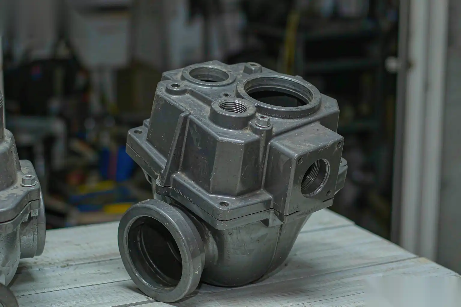
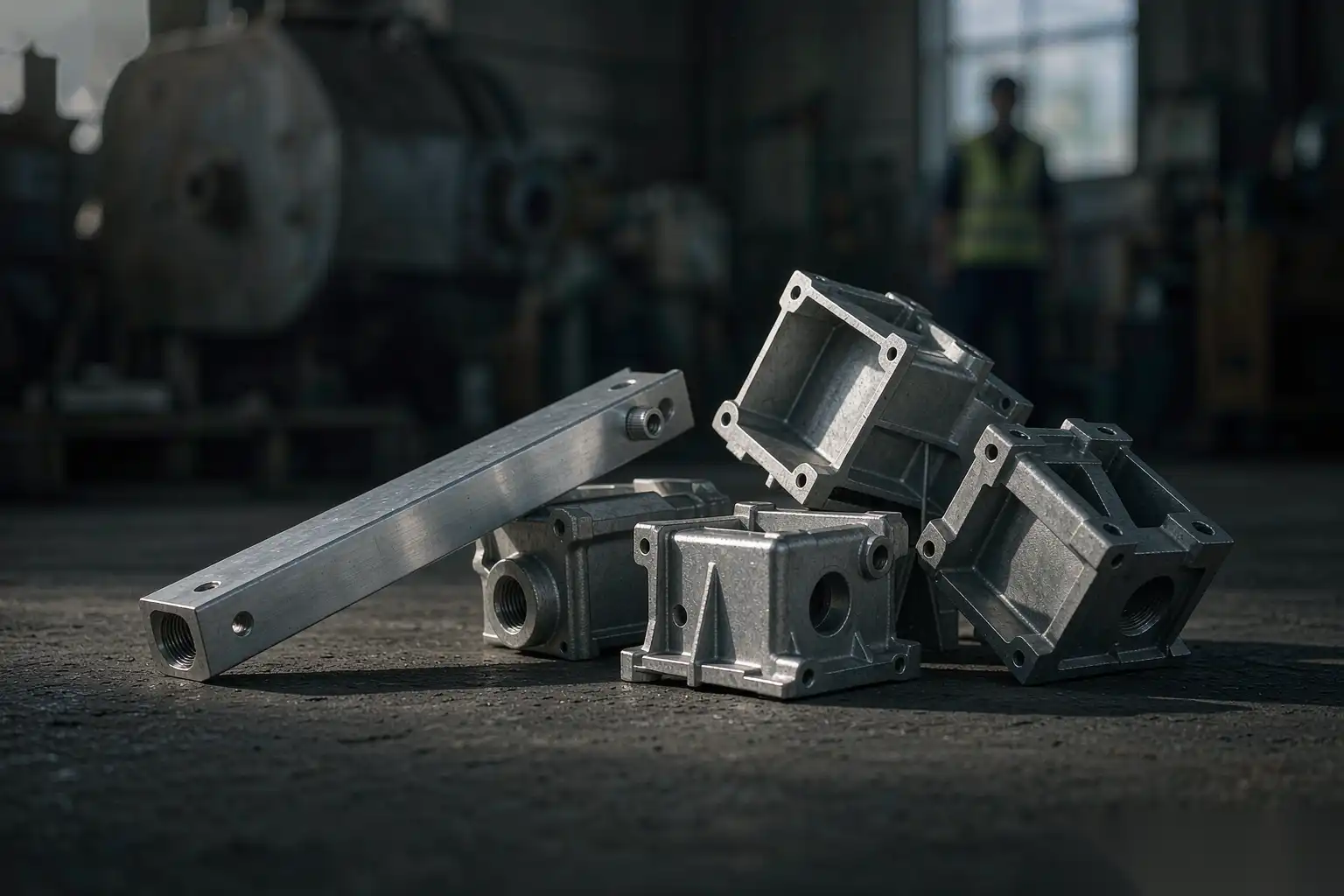
5G radio units, small-cell enclosures and baseband cabinets have turned aluminum die casting into a default choice for telecom hardware. The reason is not one property but a rare overlap: the housing must block radio frequency leakage, stay flat enough to seal against weather, pull heat out of active gear, and survive a decade outside, often in coastal or extreme climates. Stamped sheet and extrusion can do some of this, but die casting does all of it in a single near-net part with cast-in bosses, heatsink fins and gasket channels. The engineering work is in holding shielding continuity, controlling the flatness that a gasket needs, managing the thermal path, and finishing the part for outdoor life. This article covers those points and how we run a flexible cell that handles the high-mix, low-volume reality of telecom programs.
Why aluminum die casting for EMI and RF shielding
Electromagnetic interference shielding is the first reason telecom enclosures are cast, not folded. A shielded radio housing works by forming a continuous conductive shell so emitted and received signals do not leak through the seams.
- A solid aluminum wall of 2 to 3 mm gives 60 to 90 dB of shielding effectiveness across 100 MHz to 6 GHz plus, far above the 30 to 40 dB a typical gasketed seam alone provides.
- Die casting lets us cast the entire enclosure, lid and often the internal divider as one conductive family, avoiding the many lap joints of a fabricated box where each joint is a leak.
- The shielding is intrinsic to the metal, so it does not depend on a coating that can scratch or a gasket that can age. The gasket only has to cover the intentional opening at the lid.
The seam is where shielding is lost. At the lid joint the two cast faces must meet with a continuous, conductive, low-impedance contact so the gasket or the metal-to-metal interface bridges the gap. A 0.2 mm step or a 0.1 mm burr on the flange breaks that contact along a line, and along that line the radio leaks. This is why flatness and deburring of the flange are shielding issues, not just cosmetic ones.
A second shielding point is the many penetrations: connectors, cables, vents. Each is a potential leak. We design the enclosure so connector mounts are cast bosses with tight, machined seats and the gasket is captured by the lid, and we keep the number of separate stamped shields inside the box low by casting internal walls that divide the RF zones. Casting those walls is cheaper and more leak-tight than bolting in sheet dividers after the fact.
Flatness and sealing for gasketed enclosures
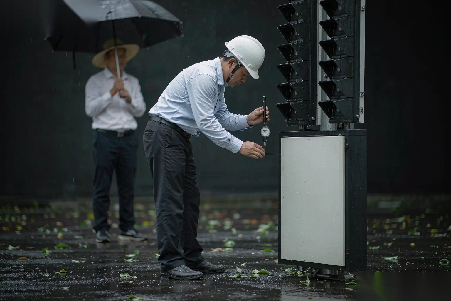
An outdoor telecom cabinet is sealed against rain, dust and temperature swing, and the seal lives or dies on flange flatness. The gasket is elastic but it has a working compression window; outside it, the seal either gaps or takes a set and creeps.
| Flange condition | Gasket behavior | Result |
|---|---|---|
| Flatness within 0.1 mm over 200 mm | Even compression 20 to 30 percent | Seal holds, no leak |
| Flatness 0.1 to 0.3 mm | Local under-compression | Intermittent weep at warp high point |
| Flatness over 0.3 mm | Gasket bridges gap | Water ingress at seam |
| Burr on flange edge | Gasket cut or displaced | Linear leak path |
For a typical 5G radio housing lid flange we hold flatness to 0.1 mm total across the seal line, measured on the machined datum. That is tighter than a general die-cast tolerance and requires both a stable casting and a controlled machining setup. Warpage after ejection is the enemy, and we control it in the die with balanced cooling and uniform wall thickness, then confirm it with the die cast warpage and flatness control guide.
The machining datum strategy is the same discipline as any sealed housing: we machine the lid seat and the body flange in reference to the same datums so the two halves meet, rather than each to its own fixture where stack-up opens the seam. Stock allowance on the flange is 0.4 to 0.6 mm per side so the cut sits above any surface porosity and the flatness is real metal, not a skim over a void. The deburring step then breaks the flange edge by 0.3 to 0.5 mm so the gasket is not sliced by a sharp lip during compression.
A common field failure is a lid that was machined flat but warps after coating because the powder bake at 180 to 200 degrees Celsius relaxed residual die stress. We pre-stress-relieve the casting where flatness is critical, either by a low-temperature thermal cycle or by aging, so the post-coat flatness stays in band. Skipping this step is the usual reason a cabinet that passed flat at machining fails the gasket test after painting.
Thermal management of active gear
A 5G radio is a heat source, often 100 to 400 W in a sealed box with no moving air inside, and the die-cast housing is the heat sink. The casting has to move that heat from the power amplifiers to the ambient through fins on the outside.
- We cast external fins 8 to 20 mm tall with 3 to 6 mm pitch, a balance that maximizes surface area without trapping the die or choking natural convection.
- Internal, we cast a flat mounting plane for the RF board with minimum wall thickness at the hot spot, typically 2.5 to 3.5 mm, so conduction is not throttled by a thick, slow section.
- Interface flatness of that mounting plane is held to 0.05 to 0.1 mm so the thermal pad or gap filler compresses evenly; a high spot there is a local hot point that shortens amplifier life.
The thermal path is a design calculation, not a guess. We estimate the junction-to-ambient resistance from the cast geometry and the expected ambient, then validate it on the first article with thermocouples at the amplifier and the fin root under a load test. If the hotspot runs more than a few degrees above the model, we widen the internal plane, add a fin, or thicken the local wall. Casting makes this cheap to iterate because the fins and planes are part of the tool, not separate parts.
One subtlety: anodize reduces thermal emissivity if it is a bright clear coat, while a matte or powder finish emits better. For a passively cooled cabinet we often specify a matte powder on the fin side for radiation, accepting that it is cosmetically busier. The finish choice is a thermal decision as much as a corrosion one, and we call it out on the drawing rather than leaving it to the coater.
Finish and coating for outdoor cabinets
Telecom cabinets sit outside for ten to fifteen years through sun, rain, salt and freeze-thaw, so the finish is the warranty. Aluminum is corrosion resistant but not inert, and a thin coastal salt film pits it within a season if unprotected.
| Location | Threat | Finish | Behavior |
|---|---|---|---|
| Inland, sheltered | UV, rain | Sealed anodize | Adequate, 8 to 12 year look |
| Roadside, winter salt | Chloride | 60 to 80 micrometer powder, chromate-free base | Best, longest life |
| Coastal | Salt spray | Powder plus edge control, 80 micrometer | Needs edge radius and thickness check |
| Rooftop, full sun | UV plus heat | UV-stable powder | Color hold, lower chalking |
We default to powder for outdoor telecom because it bridges edges and minor substrate defects that a thin anodize cannot, and it survives the mechanical abuse of installation. The base conversion layer is chromate-free for most markets, with a specified adhesion and a scribe creep limit from neutral salt spray of 480 to 1000 hours depending on the contract. Edge radius is held at 0.5 mm minimum so the coating does not thin to nothing at a lip and pit first.
The die cast aluminum enclosure design guide covers the wall, boss and divider rules we apply, and the same guide drives the gasket channel and drain details. A drain or weep at the low point of the cabinet stops water that gets past a damaged gasket from sitting against a thin wall, which is the difference between a cosmetic stain and a crevice-corrosion hole after five years.
Color and label are part of the finish spec. Cabinets are often a defined RAL or Pantone, and the coater must match a master; we audit shade per lot because batch drift is normal and a mismatched bank of cabinets on a street is a visible miss. Laser-etched labels cast or marked into the housing outlast a sticker that the sun removes in two seasons.
High-mix, low-volume handling with a flexible DZ cell
Telecom programs are the opposite of automotive volume. A radio maker runs dozens of enclosure variants, each at maybe 2,000 to 30,000 per year, with frequent design tweaks. A dedicated single-part line would sit idle. The cell has to flex.
Our flexible DZ finishing cell for telecom housings is built around:
- Quick-change fixtures on a shared base, swapped in under 15 minutes including air and I/O check.
- Stored robot and CNC programs per part number, called by barcode so the right deburring path and cut load automatically.
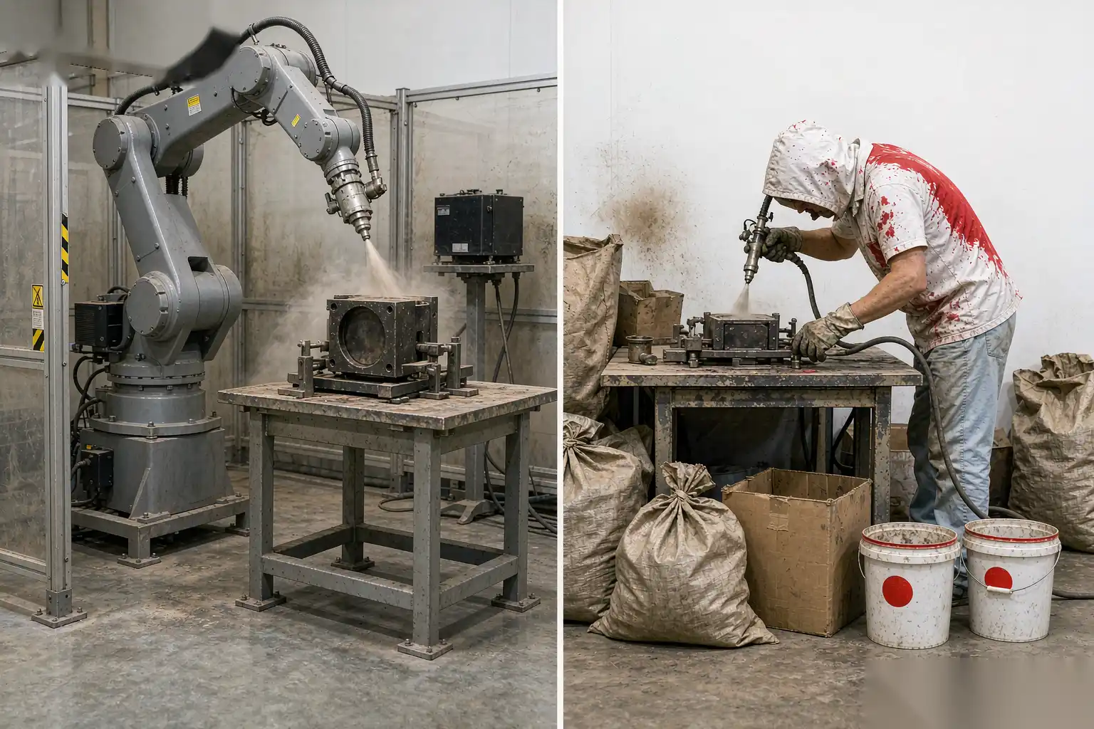
- One six-axis deburring robot with a force-controlled floating spindle handling flash, flange edges and connector-boss burrs across all variants.
- One or two machining centers for the seal faces and mounting planes, with automatic datum location so setup scatter is removed.
- Inline flatness and leak or pressure-decay check where the seal matters, feeding a per-part log.
The flexibility lives in the fixture and the program, not in the robot. The same spindle that deburrs a 2 kg small-cell lid deburrs a 12 kg baseband cabinet by loading the matching program and fixture. Tool life is logged against part count and the belts are swapped on schedule, so a low-volume run still gets a consistent edge.
Dust and safety are built in, not added. Deburring aluminum throws fine swarf; we enclose the robot with light curtains and run downdraft extraction sized to the removal rate, interlocked so a door open stops the spindle. For telecom the cell often sits in a jobbing shop serving several OEMs, so the quick changeover is what makes automation pay rather than the raw cycle time.
Process monitoring ties it together. We record spindle load, contact force, flatness result and any pressure-decay reading per part, plotted as moving averages. On a low-volume program a slow drift in flange flatness shows up in the trend days before a part fails the gasket test, which is the only way to catch a problem when you are making fifty a day, not five thousand. That logging is what lets a flexible cell run unattended on a second shift without a quality surprise at the end of the week.
Acceptance criteria for a telecom housing
| Check | Method | Frequency | Accept |
|---|---|---|---|
| Flange flatness | CMM or granite with indicator | 3 per die service, audit 2 per shift | Within 0.1 mm over seal line |
| Shielding continuity | RF leak probe at seam, qualification | Per design change | No leak above limit at band |
| Coating thickness | Gauge flat and edge | 1 per lot of 200 | 60 to 80 micrometer powder |
| Salt spray | 480 to 1000 h neutral, scribe | Per finish change | Creep under 2 mm |
| Thermal | Load test, thermocouples | First article, per change | Hotspot within model plus a few degrees |
| Dimensional | CMM on datums | 3 per die service | Plus or minus 0.1 mm features |
Shielding is qualified, not measured per part, because an RF chamber on every unit is impractical; we qualify the design and the flange process, then trust the flatness and deburring controls to hold the seam. If a flange flatness trend drifts, we treat it as a shielding risk and stop the line, because the two are the same physical fact.
The broader picture for these parts is in our aluminum die casting applications by industry guide, which shows how the same shielding, flatness and thermal discipline serves power, networking and industrial enclosure programs. For 5G and telecom the point is that the housing is not a box, it is part of the radio and the seal and the heat sink at once, and die casting is the one process that makes all three in a single part.
5G and telecom aluminum die-cast housings succeed when shielding, flatness, thermal and finish are treated as one coupled design rather than separate afterthoughts. A DZ Machinery flexible robotic deburring and finishing cell, built around quick-change fixtures, documented force windows and per-part flatness and process logging, is how we hold that coupling across a high-mix telecom program. If you are specifying an enclosure for a new radio or small-cell unit, talk to our engineering team about your drawings and we will map the shielding, sealing and thermal steps before you cut a die.