Thin Wall Aluminum Die Casting: Fill Limits, Design Rules and What It Does to Your Finishing Line
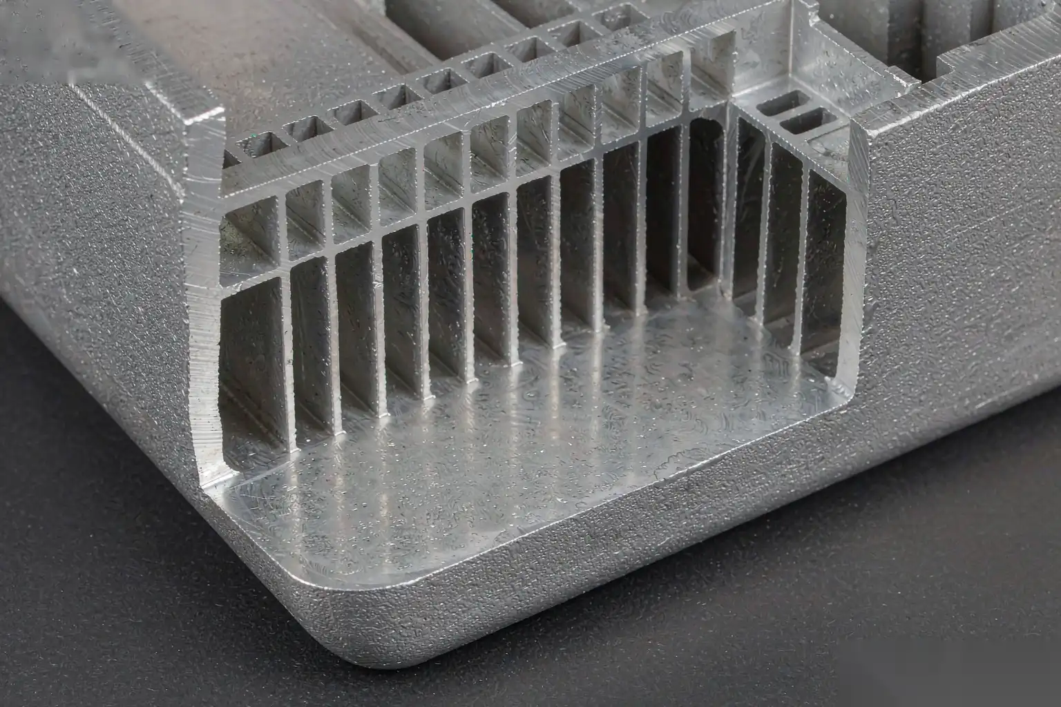
Thin wall aluminum die casting is the most effective way to take cost out of a casting: less metal per part, shorter solidification time, faster cycles. It is also the fastest way to destroy a programme if the wall is specified without considering flow length, gate velocity, distortion and what happens to the part when someone presses it against a belt.
This article is written for designers and process engineers who have to make the wall thickness decision and then live with it. It covers practical minimum wall against flow length, how to calculate fill time and size the gate, rib and fillet rules, warp prediction and control, the effect on cycle time and die life, how thin walls are actually inspected, and why a thin wall part usually forces the finishing line to become robotic.
What “Thin Wall” Means in Production Terms
Definitions vary, but on production cold chamber machines the practical bands are:
- Conventional: 2.5 to 4.0 mm nominal wall on parts up to about 1 kg.
- Thin wall: 1.2 to 2.0 mm nominal, with flow lengths up to 300 to 500 mm and gate velocities of 35 to 60 metres per second.
- Ultra thin: below 1.0 mm, generally only viable on small parts under about 100 mm in any dimension with short flow lengths and aggressive vacuum.
Wall thickness cannot be chosen in isolation from projected area, because the machine has to deliver intensification pressure over that area. The table below is a working guide for ADC12 and A380 type alloys.
| Projected area of casting | Conventional minimum wall | Practical thin-wall minimum | Typical machine size |
|---|---|---|---|
| Under 100 square centimetres | 1.2 to 1.5 mm | 0.8 to 1.0 mm | 80 to 160 t |
| 100 to 300 square centimetres | 1.5 to 2.0 mm | 1.0 to 1.3 mm | 160 to 350 t |
| 300 to 800 square centimetres | 2.0 to 2.5 mm | 1.3 to 1.8 mm | 350 to 800 t |
| 800 to 1,500 square centimetres | 2.5 to 3.5 mm | 1.8 to 2.5 mm | 800 to 1,600 t |
| Over 1,500 square centimetres | 3.0 to 4.0 mm | 2.5 mm plus | 1,600 t plus |
Two caveats apply to every row. First, the minimum wall applies to the area that metal must reach last; local features such as bosses and cored holes are always thicker. Second, minimum wall is a filling limit, not a strength or stiffness limit. A 1.2 mm wall may fill perfectly and still be unacceptable for assembly loads, thread pull-out or impact.
Flow Length Against Wall Thickness
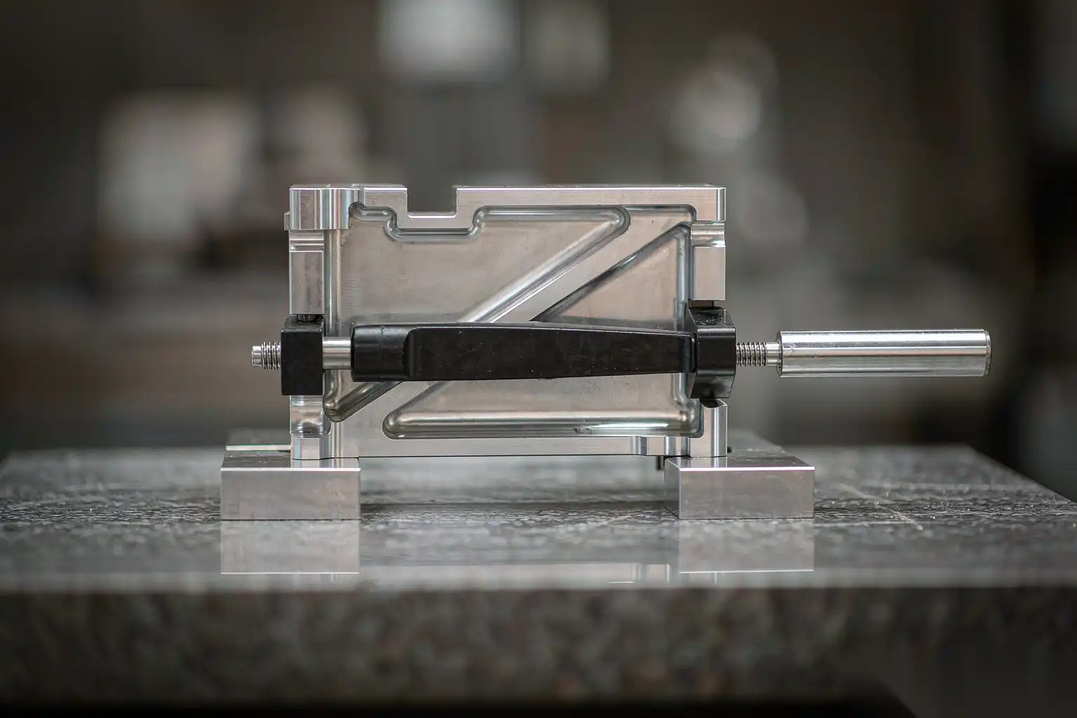
Flow length is the distance metal travels from the gate to the last point to fill. It is governed by how far the metal front can travel before it cools below the temperature at which it will still flow and weld. For ADC12 and A380, the front must stay above roughly 585 to 600 degrees Celsius; below that, misruns, cold shuts and visible flow marks appear.
| Wall thickness | Maximum flow length, conventional | Maximum flow length, vacuum plus 700 degrees Celsius metal |
|---|---|---|
| 1.0 mm | 200 to 280 mm | 300 to 380 mm |
| 1.5 mm | 320 to 420 mm | 420 to 520 mm |
| 2.0 mm | 450 to 560 mm | 560 to 680 mm |
| 2.5 mm | 560 to 700 mm | 700 to 850 mm |
| 3.0 mm | 650 to 820 mm | 820 to 1,000 mm |
| 4.0 mm | 850 to 1,050 mm | 1,000 to 1,200 mm |
The second column assumes die temperature around 200 degrees Celsius, no vacuum and a standard die lubricant regime. The third assumes cavity vacuum below 50 mbar at the end of fill and metal at 700 degrees Celsius. If your design needs more flow length than the table allows at the chosen wall, the options in order of cost are: move the gate, add a second gate, raise die temperature by 20 to 40 degrees, add vacuum, or raise the wall. Simulation is the right tool for confirming any of them, but these numbers are a good first filter before you spend days on a model.
Fill Time, Gate Velocity and Intensification
Cavity fill time is estimated from the heat balance between the incoming superheat plus latent heat and the heat lost to the die. A widely used empirical form is:
t = 0.0347 x T x (Ti minus Tf plus 30 x S) divided by (Tf minus Td)
where t is fill time in seconds, T is wall thickness in millimetres, Ti is metal temperature at the gate, Tf is the minimum flow temperature, Td is die surface temperature, and S is the tolerable fraction of solid, typically 5 to 15 percent.
Worked example for a 1.8 mm wall: Ti = 660 degrees, Tf = 590 degrees, Td = 220 degrees, S = 10.
- Numerator: 660 minus 590 plus 30 x 10 = 70 plus 300 = 370.
- Denominator: 590 minus 220 = 370.
- t = 0.0347 x 1.8 x 1.0 = 0.062 seconds, about 62 milliseconds.
That is a realistic number for a part in the 100 to 300 square centimetre class, and it drives everything else.
Gate sizing. If the casting cavity volume is 85 cubic centimetres and fill must complete in 45 milliseconds, the required flow rate is 85 divided by 0.045, about 1,890 cubic centimetres per second, or 1.89 million cubic millimetres per second. At a target gate velocity of 45 metres per second, the gate area is 1,890,000 divided by 45,000, roughly 42 square millimetres. At a gate thickness of 1.1 millimetres that is a 38 millimetre wide gate.
Gate velocity guidelines:
- Conventional parts: 25 to 40 metres per second at the gate.
- Thin wall: 40 to 60 metres per second. Above about 60 metres per second, gate erosion and die washout accelerate sharply.
- Gate thickness: 0.6 to 1.2 times the wall, typically 0.8 to 1.2 millimetres, with a land of 2 to 3 millimetres. Thicker gates extend freeze time and allow back-flow during intensification.
Intensification. Required locking force is projected area times specific pressure. For the same part with 126 square centimetres of projected area and a target specific pressure of 80 megapascals: 12,600 square millimetres times 80 newtons per square millimetre equals 1.008 meganewtons, about 103 tonnes. Add 15 to 20 percent margin and select a 160 to 200 tonne machine.
Other shot-end settings that thin wall work depends on:
- Slow shot velocity 0.2 to 0.4 metres per second with sleeve fill of 35 to 45 percent, to avoid wave formation and air entrainment.
- Intensification pressure rise time under 20 to 30 milliseconds, verified with a shot-monitoring trace rather than assumed from the machine setting.
- Die temperature 180 to 250 degrees Celsius, held with conformal or baffled cooling near the gate, because thin sections lose superheat faster than the die can replace it.
Ribs, Fillets, Draft and Section Transitions
| Feature | Recommended | Hard limit | What happens if violated |
|---|---|---|---|
| Rib thickness | 0.6 to 0.8 times adjacent wall | Over 1.0 times wall | Sink marks, porosity at rib root |
| Rib height | Up to 3 to 5 times wall | 6 times wall | Fill failure at rib tip, die erosion |
| Rib root fillet | R = 0.5 to 1.0 times wall, minimum 0.5 mm | Under 0.3 mm | Crack initiation, hot spots, die heat checking |
| Rib draft | 0.5 to 1.0 degree per side | Under 0.25 degree | Drag marks, bush damage, ejection force spike |
| Internal corner radius | 1.0 to 1.5 mm preferred | Under 0.5 mm | Stress concentration, die cracking at the corner |
| External corner radius | Internal radius plus wall | Zero radius | Sharp die edge that chips |
| Draft, internal surfaces | 1.0 to 2.0 degrees per side | Under 0.5 degree | Sticking, distortion on ejection |
| Draft, external surfaces | 0.5 to 1.0 degree per side | Under 0.25 degree | Drag on the cavity half |
| Cored hole diameter | 3.0 mm minimum | Under 2.5 mm | Core breakage, unacceptably short core life |
| Cored hole depth | Up to 5 to 8 times diameter | Over 10 times diameter | Core deflection, wall thickness drift |
| Section transition | Taper over 3 to 5 times the thickness difference | Abrupt step | Hot spot, shrinkage porosity, visible flow mark |
The rule behind all of these is the same: every place where local section thickness exceeds the nominal wall becomes a hot spot, and every hot spot in a thin wall part is a potential shrinkage void, because there is no adjacent reservoir of liquid metal to feed it.
Warp and Distortion: Prediction and Control
Aluminium shrinks about 0.5 to 0.6 percent linearly on solidification. If that shrinkage is uniform and the part is free, the casting simply gets smaller. Warp happens when shrinkage is non-uniform: different section thicknesses cool at different rates, and the die constrains the part until ejection, so the stresses released on ejection bend the casting.
The pattern we see most often is the one-sided rib. A 240 millimetre long housing with a 1.8 millimetre wall and four ribs on the inside face, none on the outside, will typically bow 0.8 to 1.5 millimetres along its length. The standard corrections, in order:
- Mirror the ribbing. Add ribs on the opposite face at 0.5 to 0.7 times the height of the primary ribs. This keeps most of the stiffness and halves the thermal asymmetry.
- Balance the cooling. Run the cavity half on the ribbed side 20 to 40 degrees hotter so both faces reach ejection temperature together. On the example above this alone typically brings bow below 0.5 millimetres.
- Balance ejection. Place ejector pins within 10 to 15 millimetres of every rib and boss, size the pins for the local load, and verify ejection with a pressure trace. Unbalanced ejection bends a thin part regardless of how well it was filled.
- Control the quench and the stack. Thin parts cool fast and unevenly in a water quench. Use air cooling or a controlled fixture, and never stack thin wall parts loose in a bin while they are above 150 degrees Celsius.
- Straighten or stress relieve only as a last resort. A controlled press operation with a defined deflection limit works on ductile alloys; thermal stress relief at 180 to 220 degrees Celsius for 2 to 4 hours reduces residual stress, but above roughly 350 to 400 degrees Celsius entrained gas expands and blisters appear, so heat treatment of HPDC parts has a narrow window.
Simulation is worth doing here, but treat the numbers honestly: a coupled fill, solidification and stress model will usually predict the direction and rough magnitude of warp correctly, and the absolute value within 30 to 50 percent. That is enough to choose between design alternatives, not enough to skip the first article measurement.
Cycle Time, Die Life and Cost Consequences
The benefit of thin wall is solidification time, which scales roughly with the square of section thickness. Using a modulus-based estimate of t = B x M squared, with M half the wall thickness and B around 0.15 to 0.25 seconds per square millimetre for aluminium in a well-cooled H13 die:
- 1.5 mm wall: 0.3 to 0.6 seconds.
- 2.0 mm wall: 0.6 to 1.0 seconds.
- 3.0 mm wall: 1.4 to 2.3 seconds.
- 4.0 mm wall: 2.4 to 4.0 seconds.
Solidification is only part of the cycle, but on thin wall parts it stops being the dominant term, and total dry cycle commonly drops from 45 to 60 seconds to 25 to 35 seconds. Metal per part drops 20 to 40 percent. Those two numbers are the business case.
The costs show up in three places:
- Machine size. Thin wall needs higher specific pressure and higher gate velocity, so the same part often moves up one or two machine sizes. Tonnage is paid for whether or not it is used.
- Die life. Conventional aluminium dies on H13 run 80,000 to 150,000 shots before major rework. With gate velocities of 45 to 60 metres per second and thin gate lands, gate erosion and washout typically shorten that to 50,000 to 100,000 shots. Heat checking on the gate pad can begin at 20,000 to 50,000 shots. Premium ESR hot-work steel, nitriding to a 0.10 to 0.15 millimetre case at 1,000 to 1,100 HV, and conformal cooling all help, all cost money.
- Process window. Thin wall runs closer to the misrun boundary. A 30 degree drop in metal temperature or a die that has cooled over a break can move scrap from 1 percent to 10 percent in a shift. Monitoring and discipline are not optional.
Inspecting Thin Walls
Thin wall parts defeat conventional inspection technique in two ways: the part deflects under the measuring force, and the failure mode is internal.
- Contact CMM. Use a low probing force, 0.1 to 0.3 newtons, and support the part on the datum features used in the fixture, not on a flat plate. A 1.2 millimetre wall measured with a standard 0.5 newton probe can deflect 0.05 to 0.10 millimetres, which is a significant fraction of the tolerance.
- Optical and structured light scanning. Accuracy of 0.02 to 0.05 millimetres on free-form surfaces, with the advantage of full-field data. Good for form and for detecting local sink, but it does not see internal voids.
- Computed tomography. This is the tool for wall thickness and internal porosity on thin wall parts. Voxel sizes of 30 to 80 micrometres resolve wall thickness to roughly plus or minus 0.02 millimetres and detect pores down to about 0.15 millimetres. A full scan takes 5 to 20 minutes, so it is a sampling and first-article method, not an in-line one, typically 1 part in 200 to 1,000 plus 100 percent at launch.
- Ultrasonic thickness. Works above about 1.0 millimetre with 0.01 millimetre resolution, but it is unreliable on curved surfaces and on coarse-grained regions, and needs correlation against microsections.
- Leak testing. Pressure decay at 3 to 6 bar with limits of 1 to 5 cubic centimetres per minute for most housings; helium mass spectrometry down to 1 x 10 to the minus 5 mbar litres per second for refrigeration and pressure vessels.
For tolerances, thin wall parts are frequently held to ISO 8062-3 DCTG 4 or 5 on critical dimensions rather than the DCTG 6 that is typical of general die castings, which is achievable but has to be designed for. The interaction between achievable tolerance, wall thickness and machining allowance is set out in our aluminum die casting tolerances guide, and the fill-related defects that thin walls are prone to are covered in aluminum die casting defects and solutions.
What Thin Walls Do to the Finishing Line
The last consequence is the one that surprises people. A 1.2 to 1.8 millimetre wall with a gate stub on it is a difficult object to grind by hand.
- Deflection under load. A manual operator applying 40 to 80 newtons to a belt will deflect a thin wall elastically. The belt rides over the gate instead of cutting it, the operator pushes harder, and the result is a dish in the panel or breakthrough at the gate.
- Heat. Local grinding heat above roughly 120 degrees Celsius anneals the surface locally and, on a thin section, distorts the part. That distortion is permanent once the part cools.
- Dimensional loss. On a 1.2 millimetre wall there is no stock budget for a gouge. Manual rework scrap on thin wall parts is commonly two to three times the rate on conventional parts.
A robotic cell changes the mechanics. With a force-controlled floating spindle holding contact force at 5 to 25 newtons instead of 40 to 80, with the fixture backing the wall within 5 to 10 millimetres of the contact point, and with a programmed path that never dwells, the same gate is removed with a residual height held inside plus or minus 0.08 millimetres. Belt speed stays high, 25 to 30 metres per second, and grain stays sharp, so the metal is cut rather than pushed.
The rest of the finishing line has to follow the same logic. Handling between stations has to support the part rather than let it hang or drop into a bin. Polishing, if required, has to run with the same force discipline as grinding. And inspection has to measure the part in the same state it will be assembled in, which usually means a fixture rather than a bench.
DZ Machinery builds robotic deburring, grinding and polishing cells for thin wall die castings, from single cells with force-controlled floating spindles and automatic media changers to complete lines that carry the part from band saw through CNC, robotic grinding, automatic polishing and inspection without releasing it from its datum. If you are designing a thin wall part, the useful moment to talk to us is before the die is cut: send the model and the wall thickness distribution, and we will tell you where the gates can be placed so the finishing cell can reach them, what cycle time the part will run, and what the scrap risk looks like at that wall thickness.