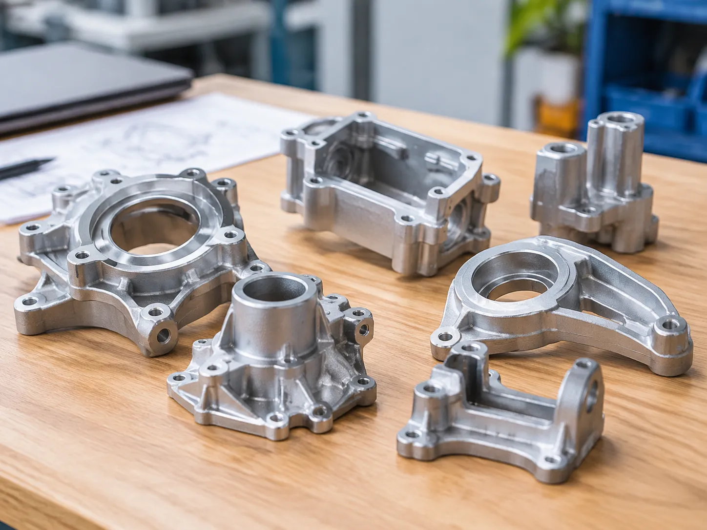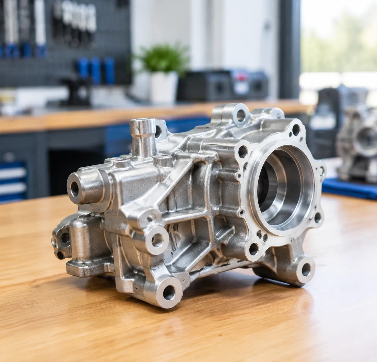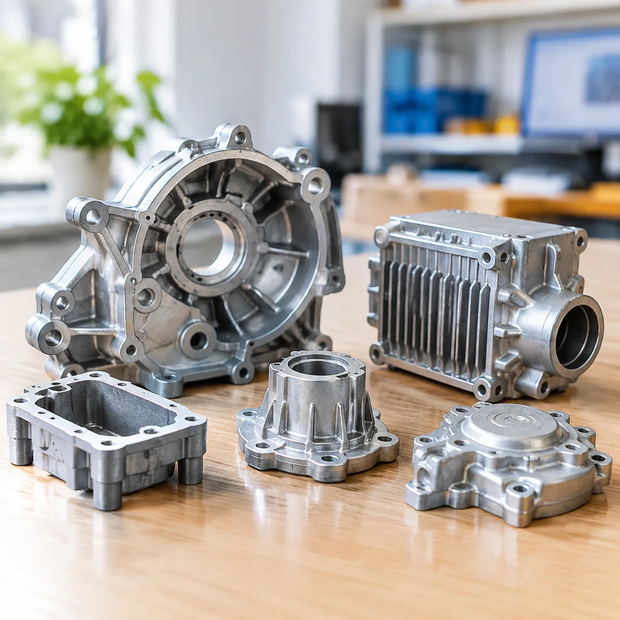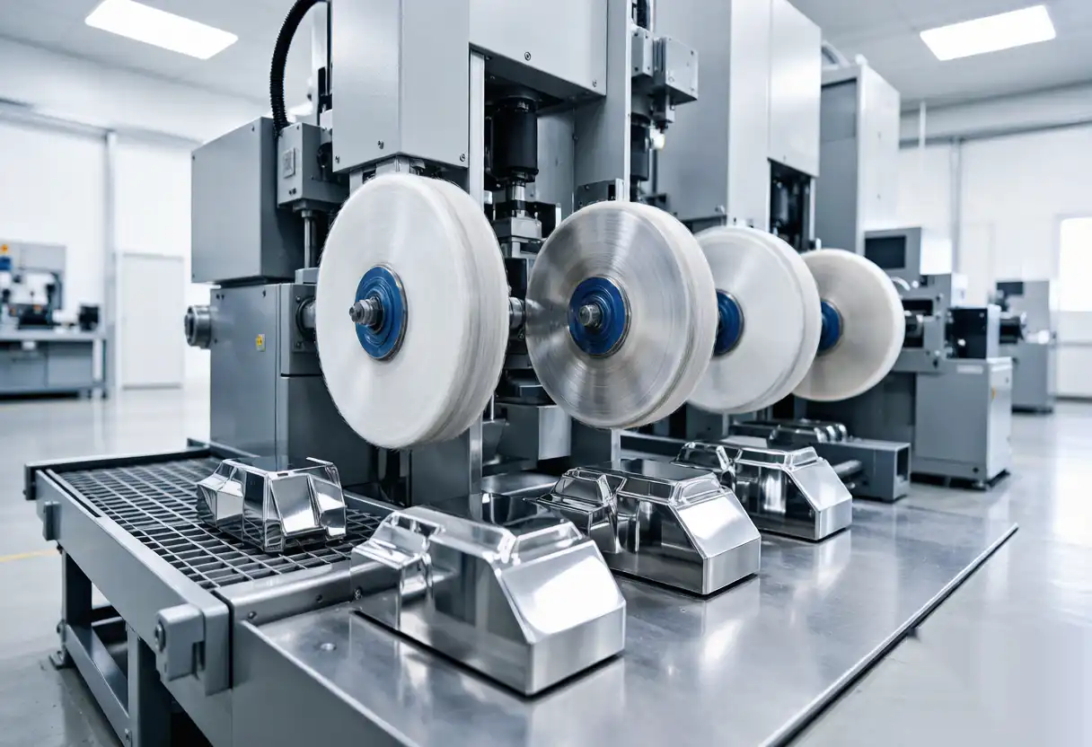
Automated mirror polishing achieves a flawless, highly reflective surface by combining a pristine ground substrate, a precise compound progression, and active force-controlled robotic motion. Achieving a true #8 mirror finish (Ra < 0.05 µm) depends far less on raw machine power and far more on disciplined process repeatability, kinematic precision, and thermal control — the core foundations of our automated surface polishing program.
In high-volume manufacturing, surface finishing is frequently the bottleneck that compromises overall quality and increases scrap rates. Manual buffing relies on operator feel, leading to inconsistent contact pressure, edge rounding, and unpredictable compound consumption. Transitioning to automated robotic polishing transforms mirror finishing from an artistic trial-and-error process into an engineered science governed by repeatable parameters.
Start With a Clean Substrate: Grit Progression and Ra Targets
A mirror finish acts as a magnifying glass for surface defects: every residual scratch, pit, or micro-tear from early stages will distort light reflection once high gloss is applied. Attempting to buff out heavy grinding marks with fine polishing compounds causes severe surface haze, compound buildup, and excessive cycle times. The grinding stage must reach a uniform roughness average (Ra) before polishing begins; skipping abrasive grits guarantees a cloudy, defective result.
A structured pre-polishing abrasive sequence must gradually flatten peak-to-valley profile heights (Rz) while maintaining dimensional tolerances. The table below outlines the standard multi-stage abrasive progression required prior to compound buffing:
| Process Stage | Abrasive Media / Grit Size | Target Surface Roughness (Ra) | Primary Objective |
|---|---|---|---|
| Coarse Pre-Grind | P80 – P120 Zirconia / Ceramic | 1.6 µm – 3.2 µm | Remove casting seams, heavy scale, and weld beads. |
| Intermediate Grind | P220 – P400 Aluminum Oxide | 0.4 µm – 0.8 µm | Eliminate deep directional scratches and level surface peaks. |
| Fine Pre-Polish | P800 – P1200 Silicon Carbide | 0.1 µm – 0.2 µm | Uniform micro-smoothing to prepare substrate for liquid compounds. |
| Mirror Polish Pass | Cotton Buff + Sub-Micron Compound | < 0.05 µm (Ra) | Eliminate all micro-haze for true optical specular reflection. |
The Compound Sequence and Buffing Wheel Dynamics
Achieving optical clarity requires matching abrasive grain types, binder vehicles, and wheel construction to the specific metallurgy of the workpiece. Modern automated cells utilize solid bar compounds with auto-feed devices or liquid emulsion sprays metered directly onto rotating buffing wheels.
- Stage 1: Heavy Cut Pass (Tripoli or Fast-Cut White Silica) — Paired with treated sisal or bias-cut hard cotton wheels. This phase removes residual P1200 fine grinding scratches, levels micro-irregularities, and establishes a baseline semi-bright surface. Surface speed is kept high (28–35 m/s) to generate sufficient frictional heat to activate binder carriers.
- Stage 2: Color and High-Gloss Pass (Green Chrome Oxide or Pink Rouge) — Paired with soft, unbleached cotton buffing wheels or open-face flannel mops. The ultra-fine abrasive particles gently polish without cutting deeply, refining surface roughness below Ra 0.05 µm and producing deep specular reflectivity.
- Stage 3: Protective Wax or Ultra-Fine Final Cleansing Pass — Applies a liquid micro-crystalline wax coat or liquid spray cleaner using ultra-soft flannel wheels. This step strips residual compound binder, prevents oxidation on non-ferrous alloys, and delivers optical image clarity (DOI > 95%).
Matching compound formulation with metal alloy chemistry is critical to prevent galling, drag lines, or chemical discoloration. Refer to our comprehensive polishing compound guide to optimize chemical compatibility across stainless steel, aluminum, brass, and titanium substrates.
Force Compliance and Kinematic Path Control
The primary failure of manual polishing—and rigid non-compliant automation—is force variation. When an unyielding robot path moves across a curved surface, minor casting dimensional tolerances or buffing wheel wear lead to drastic changes in contact force. Excessive force burns compound binders onto the substrate, while insufficient force leaves hazy, unpolished patches (light/dark optical banding).
Modern 6-axis industrial robots solve this through active force compliance tooling or closed-loop force sensors integrated into the wrist or polishing spindle. Active force compliance maintains a constant normal force (typically between 15 N to 50 N, adjustable within ±1 N) regardless of buff wheel erosion, casting variance, or complex 3D contours. Integrating dynamic pressure maintenance into a robotic polishing machine guarantees perfectly uniform light reflection on freeform surfaces, taps, sanitary valves, and automotive trim.
Root Cause Analysis: Polishing Defect Troubleshooting Guide
When mirror finishing falls short of specification, systematically diagnosing process parameters prevents costly re-work and scrap. Use this defect troubleshooting matrix to quickly identify root causes and corrective actions:
| Defect | Visual Manifestation | Root Cause | Engineering Fix |
|---|---|---|---|
| Surface Haze / Cloudiness | Milky, non-reflective sheen over polished areas. | Skipped abrasive grit step; excess grease binder. | Re-grind substrate to fine grit (P1200); reduce compound dosing. |
| Banding / Tiger Stripes | Alternating bright and dull parallel lines across curves. | Fluctuating tool contact pressure or uneven manual pushing. | Enable active force compliance (constant 25N) and smoothen robot velocity. |
| Thermal Burn / Discoloration | Blue/yellow oxidation streaks or baked compound crust. | Excessive peripheral wheel speed (RPM) or lack of lubrication. | Lower wheel surface speed below 25 m/s and increase liquid compound application. |
| Orange Peel Texture | Bumpy, uneven surface reflection resembling fruit skin. | Over-polishing soft metals with excessive contact force. | Reduce compliance pressure, switch to harder stitched wheel, shorten cycle time. |
| Micro-Scratch Tail Lines | Fine directional scratches visible under direct spotlight. | Cross-contamination between coarse and fine polishing wheels. | Isolate buffing wheels by stage; dress wheels regularly to remove dried swarf. |
QUICK TIP FOR IN-PROCESS AUDITING
If you can see a clear image reflection under LED raking light with zero micro-haze or distortion, your abrasive progression and compound lubrication are correctly balanced. If image borders appear blurry, step back one grit level before applying color compound.
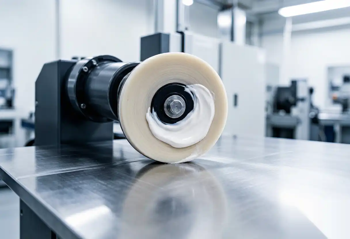
Manual vs. Automated Mirror Finishing: Operational Comparison
Transitioning from skilled manual polishers to robotic surface finishing automation provides measurable operational benefits across throughput, quality, and consumables efficiency:
| Performance Metric | Manual Hand Buffing | Robotic Force Compliance Cell |
|---|---|---|
| Quality & Ra Repeatability | Variable (Operator fatigue, shifting pressure) | 100% Consistent (Ra < 0.05 µm across all shifts) |
| Cycle Time Consistency | High variance; prone to slowing down over long shifts | Fixed tact time; continuous 24/7 production capability |
| Consumables Usage (Compound/Buffs) | High waste (over-application, uneven wear) | 30%–40% reduction through metered liquid dosing |
| Scrap & Re-work Rate | 5% – 15% (edge rounding, thermal burn) | < 0.5% after path and force parameter lock |
| Workplace Safety & EHS | High exposure to dust, noise, vibration, and strain | Enclosed cell with integrated dust collection system |
Verify, Don’t Guess: Surface Quality Control Protocols
Validating mirror finishes requires quantifiable inspection standards rather than subjective visual checks. Implementing rigorous QA protocols inside your finishing line ensures full compliance with international standards.
- Stylus Profilometry: Measure average roughness (Ra), mean roughness depth (Rz), and peak count (Ppc) according to ISO 4287. A true commercial #8 mirror finish requires Ra ≤ 0.03–0.05 µm.
- Optical Glossmeter Testing: Measure specular gloss at a 20° or 60° incident light angle in accordance with ASTM D523 / ISO 2813. Mirror metal surfaces should register gloss values exceeding 800 GU (Gloss Units).
- Raking-Light Inspection Booths: Position high-intensity LED light sources at a shallow 15° angle relative to the surface. Raking light amplifies minute scratch patterns and pressure banding that normal ambient lighting obscures. Consult our detailed quality control guide for full laboratory testing standards.
Frequently Asked Questions
What Ra is considered a true ‘mirror finish’?
A standard commercial #8 mirror finish typically requires an Ra value under 0.05 µm (2 micro-inches). High-precision sanitary fittings, semiconductor components, or pharmaceutical vessels often demand Ra < 0.02 µm accompanied by electropolishing.
Why does my metal surface look hazy after coloring compound application?
Haze is almost always caused by jumping grit sizes during pre-grinding, applying excessive contact force during final buffing, or using an overly rich compound mixture that deposits unburned grease binder onto the workpiece surface.
Can industrial robots achieve true optical mirror finishes on complex 3D castings?
Yes. By combining 6-axis articulated robot arms with active force compliance, the polishing tool dynamically conforms to 3D contours while keeping continuous surface speed and normal contact pressure, eliminating manual hot spots.
What is the difference between cut compound and color compound?
Cut compounds (such as Tripoli) contain coarse, aggressive abrasive grains engineered to level pre-grinding scratch marks. Color compounds (such as Green Chrome Oxide or Pink Rouge) utilize soft, sub-micron abrasives designed strictly to enhance gloss and light reflectivity without cutting away measurable material thickness.
How does active force compliance improve wheel lifespan?
Rigid robotic paths exert excessive force as buffing wheels compress against metal edges, rapidly destroying wheel fibers. Active compliance maintains constant soft contact force, accommodating wheel wear dynamically and extending buffing wheel lifespan by up to 50%.
Need Help Specifying the Right Polishing Machine?
Selecting the right automated system depends on your alloy composition, part geometry, target cycle time, and production volume. Talk to the application engineers at Xiamen Dingzhu Intelligent Equipment — we size custom grinding, polishing, and surface finishing systems tailored to your castings, volume targets, and surface specifications. Explore our complete range of high-efficiency automatic grinding machines and multi-axis automatic polishing machines today.
References
- Surface Finish Designation and Measurement Standards ISO 1302 — iso.org
- American Foundry Society (AFS) Technical Finishing Guidelines — afsinc.org
- ISO 4287: Geometrical Product Specifications (GPS) — Surface Texture Profile Method