Force-Controlled Robotic Grinding: Compliance That Protects the Surface
Why position control alone gouges variable castings
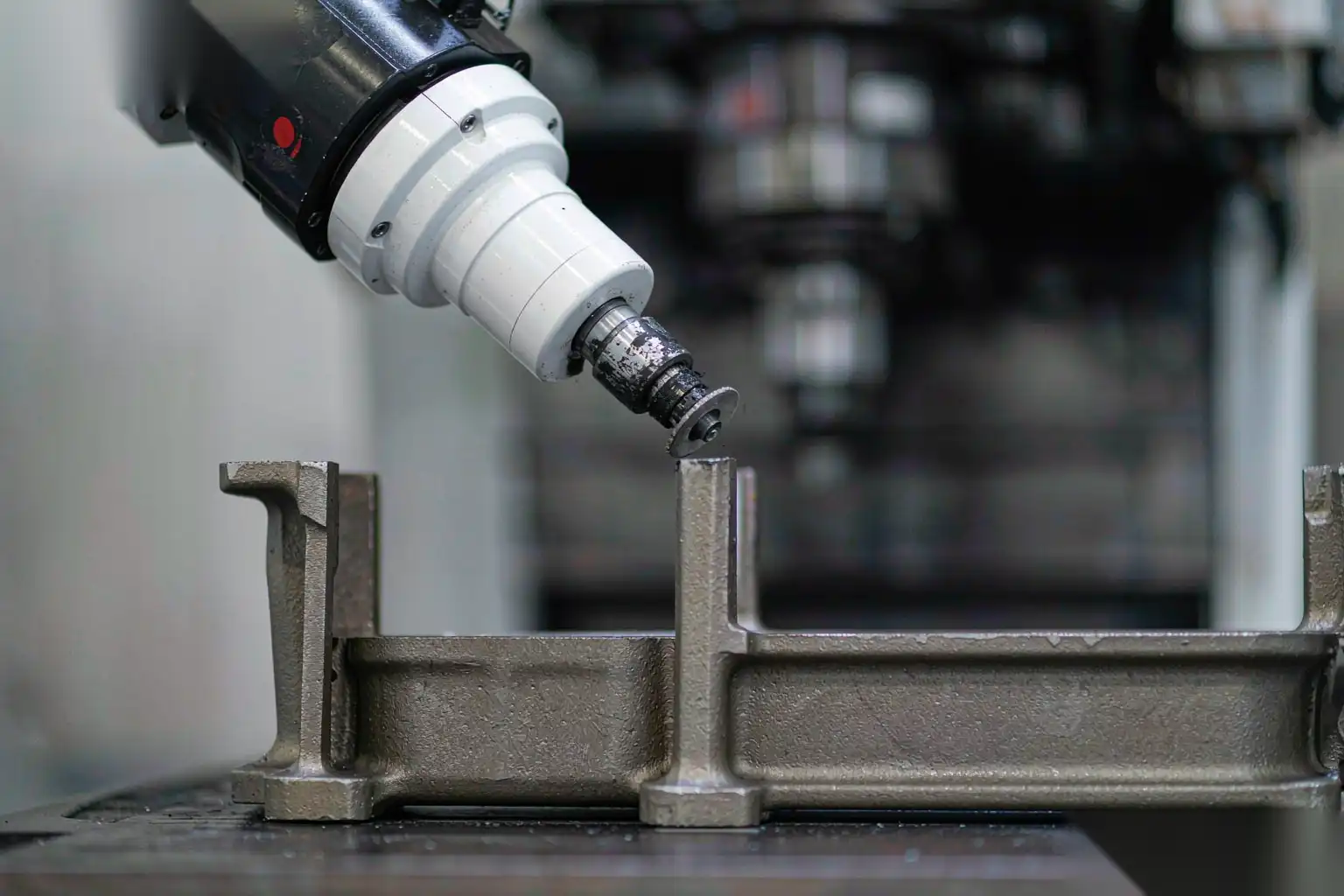
A six-axis robot is a precision positioning machine. Teach it a path and it will follow that path in Cartesian space to within roughly 0.02 to 0.1 mm, repeatably, for millions of cycles. That precision is exactly the problem when the part in the fixture is not the nominal CAD model. Die castings vary. A casting can be 0.1 to 0.5 mm proud of nominal at a gate scar, 0.2 mm low at a sink-prone wall, or twisted 0.3 mm out of plane from warpage. Run a rigid grinding path against that variation and the contact force swings from zero to several hundred newtons across a single pass.
When force spikes, the grinding wheel bites. On aluminum at 25 to 40 m/s belt speed, a 200 N contact can remove 0.3 to 0.8 mm of material in a fraction of a second where the part is proud, and remove nothing where it is low. The result is a surface that is scalloped, gouged at high spots, and untouched at low spots. Position control protects the robot, not the part. For a cosmetic faucet body or a sealing face that must hold a gasket, that variation is a scrap event.
Force control changes the control objective. Instead of commanding a fixed position and accepting whatever force results, the cell commands a target contact force and lets the robot or the spindle float to maintain it. The part variation is absorbed by compliance, not by the surface.
Active vs passive compliance
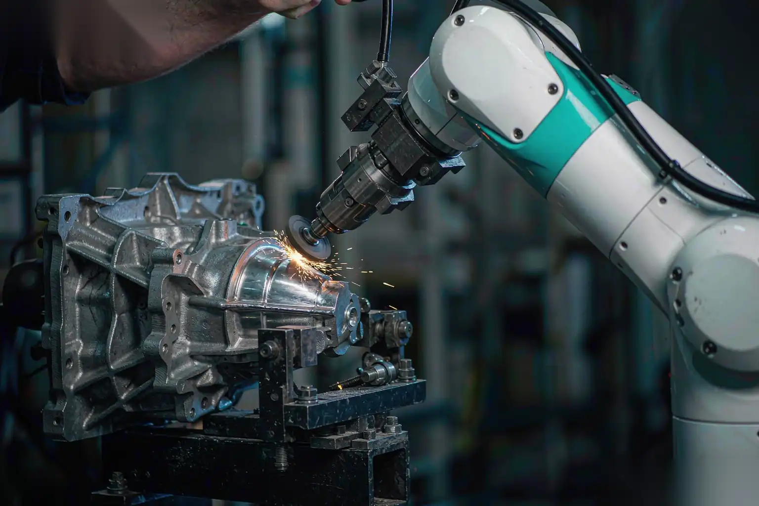
There are two ways to make a robot grinder yield to the part. Both belong in a DZ cell, and the choice depends on the force range and the cycle.
Passive compliance uses mechanical float. A pneumatic or spring-loaded floating head lets the spindle ride up and down against an air cushion or a spring stack. The force is set by air pressure or spring preload. A typical pneumatic float runs 20 to 120 N, adjustable by a regulator in roughly 5 N steps. The response is fast and cheap, with no extra control loop, but the force drifts with air pressure and the spring rate is not linear across the travel. Passive compliance is the right choice for removing external flash where the tolerance band is, say, plus 0.3 mm, and the surface does not need a mirror finish.
Active compliance uses a force-torque sensor at the wrist or in the spindle, a servo that drives a linear or rotary浮动 axis, and a closed loop that holds force to a setpoint. A six-axis force-torque sensor reading at 10 to 1,000 Hz feeds a controller that moves the robot or the浮动 head to keep contact at, for example, 45 N plus or minus 3 N. Active systems cost more and need tuning, but they hold force through corners, over varying radii, and across a part that is 0.5 mm out of nominal. Table 1 summarizes the trade.
| Compliance type | Force band | Response | Best use | Typical cost add |
|---|---|---|---|---|
| Passive pneumatic float | 20 to 120 N | Fast, pressure-dependent | External flash, rough grind | Low |
| — | — | — | — | — |
| Passive spring float | 10 to 80 N | Fast, nonlinear | Light deburring, brushing | Low |
| Active force-torque servo | 5 to 300 N | Closed loop, ±2 to 5 N | Cosmetic grind, polish prep | Medium to high |
For most DZ cells we run passive float on the roughing station and active force control on the finishing station, so material is knocked off fast first and held tight later.
Force feedback loops and settling
An active force loop has the same anatomy as any servo: a setpoint, a measured value, an error, and a correction. The measured value comes from the force-torque sensor. The correction drives a servo axis or a small robot move. The tuning matters because grinding is a stiff contact, and a stiff contact loop with too much gain chatters.
The loop runs in three phases per pass:
- Approach. The robot moves toward the surface in position mode until contact is detected, usually a force threshold of 5 to 15 N.
- Settling. Once contact is detected, the controller switches to force mode. The measured force overshoots the setpoint by 10 to 30 percent in the first 50 to 200 ms as the compliance takes up slack. A well-tuned loop settles in under 150 ms.
- Track. During the grind the loop holds setpoint within band while the wheel wears. As the abrasive dulls, the robot advances by a few microns per pass to keep force constant, which is why force control also stabilizes wear rate.
A loop that is tuned too stiff will oscillate, leaving a washboard pattern at 20 to 60 Hz on the part. A loop too soft lets force sag at corners, where centripetal load drops contact. We tune the proportional and derivative gains against the actual part stiffness on the fixture, not against a bench test, because fixture deflection of 0.05 to 0.2 mm changes the effective contact as much as the casting variation does. That fixture stiffness is the reason we plan locating and clamp strategy together with the finishing process, as covered in our robotic finishing fixture design work on flatness and datum control.
Matching force to remove-rate by material
The contact force sets how much material comes off per second, and the relationship is material-specific because hardness and melting behavior differ. Table 2 gives working bands we use on DZ cells.
| Material | Suggested force | Belt or wheel speed | Remove rate | Risk if too high |
|---|---|---|---|---|
| Aluminum A380/ADC12 | 30 to 70 N | 25 to 38 m/s | 0.5 to 2.0 cm³/min | Loading, smearing, gouge |
| Zinc Zamak | 20 to 50 N | 20 to 32 m/s | 0.4 to 1.5 cm³/min | Dimensional loss, heat |
| Magnesium | 15 to 40 N | 18 to 28 m/s | 0.3 to 1.2 cm³/min | Spark, fire risk |
| Stainless 304/316 cast | 50 to 120 N | 20 to 30 m/s | 0.2 to 0.8 cm³/min | Work hardening, orange peel |
| Brass | 25 to 55 N | 22 to 34 m/s | 0.4 to 1.6 cm³/min | Loading, built-up edge |
The key behavior on aluminum is smearing. Past about 70 N with a dull belt, aluminum does not cut cleanly; it smears and fills the belt, raising friction and heat until the surface turns grey and the Ra climbs from 0.8 to 3.0 µm or worse. Force control prevents this because it holds the wheel at the cut, not into the part. On stainless the opposite risk dominates: too little force lets the belt rub and work-harden the surface, raising hardness from 180 to 280 HV locally and ruining the later polish. Force control keeps the belt in the cut where it belongs.
Remove rate also sets cycle time. If a gate scar needs 4 cm³ removed and the cell runs aluminum at 1.5 cm³/min, that feature takes roughly 2.7 min of contact, plus approach and retract. Force control lets you push the upper end of the band safely, because the loop backs off if the part is proud instead of gouging.
How compliance protects tolerances and downstream polish
The downstream benefit of force control is consistency, and consistency is what the next process needs. Three effects matter:
- Dimensional control. Holding force to plus or minus 5 N holds the cut depth to within roughly 0.05 to 0.15 mm across a variable casting, so a sealing face stays in its plus 0.2 mm band instead of being gouged to minus 0.3 mm.
- Surface uniformity. A constant force gives a constant Ra, typically 0.4 to 1.6 µm on a 120 to 240 grit belt, with no scallops. The polish station that follows sees the same starting surface everywhere, so the buffing compound and time are predictable.
- Tool life. Because force is capped, the belt or wheel wears evenly instead of spiking at high spots. We see belt life improve 20 to 40 percent when moving from rigid to force-controlled grind on the same part.
For a faucet or lock face that goes to polish, this is the difference between a cell that needs an operator watching for gouges and one that runs unattended. The automated aluminum deburring we deploy always pairs the rough robot with a force-controlled finish robot for exactly this reason.
Fixture stiffness is part of the force loop
A point that gets missed: the force loop measures the net deflection of robot, spindle, floating head, fixture, and part. If the fixture deflects 0.15 mm under 50 N, the sensor sees only the residual, and the robot floats into the deflection thinking it is following the part. The part then gets cut where the fixture is soft. We design fixtures for finishing with a stiffness target of at least 1 to 2 N per micron at the contact point, which usually means a three-point datum, a solid rest, and a clamp that pulls against the rest rather than floating the part.
Clamp location also matters. A clamp near the contact point stiffens the cut; a clamp far from it lets the part ring at 80 to 200 Hz and the force loop fights the resonance. We locate clamps within one part thickness of the grind zone wherever the geometry allows, and we damp the fixture with elastomer pads only where the part itself is fragile. For parts prone to warpage and flatness loss, we add a support pin at the low corner so the robot is not grinding against a twist.
Tuning procedure we use on a DZ cell
Setting up force control is repeatable if you follow a sequence rather than guessing gains:
- Mount the part and measure its actual standout at three points with a probe; record the variation.
- Set the passive or active float to the material band from Table 2, starting at the low end.
- Run one pass and log force and Ra; if Ra is high and the belt loads, lower force 10 N.
- If the surface is grey or smeared, lower force and increase belt speed 5 m/s.
- Increase gain in small steps until the loop settles under 150 ms without chatter; back off one step if washboard appears.
- Lock the setpoint and run 30 parts, measuring Ra and cut depth on every fifth part to confirm the band.
This procedure takes a DZ engineer roughly half a day on a new part and removes the trial-and-error that otherwise burns belts and scrap.
When force control is not enough
Force control solves variation, not everything. It will not remove a burr the tool cannot reach, which is why cells still need thermal or vibratory steps for internal features. It will not fix a part that is out of flatness by more than the float travel, roughly 5 to 10 mm on a passive head, because the robot runs out of compliance. And it will not hide a porosity blowout; if the belt opens a pore, force control just follows the hole. Those limits are why we treat force-controlled grinding as one station in a full finishing sequence, not as a standalone answer.
Bringing DZ into your grinding cell
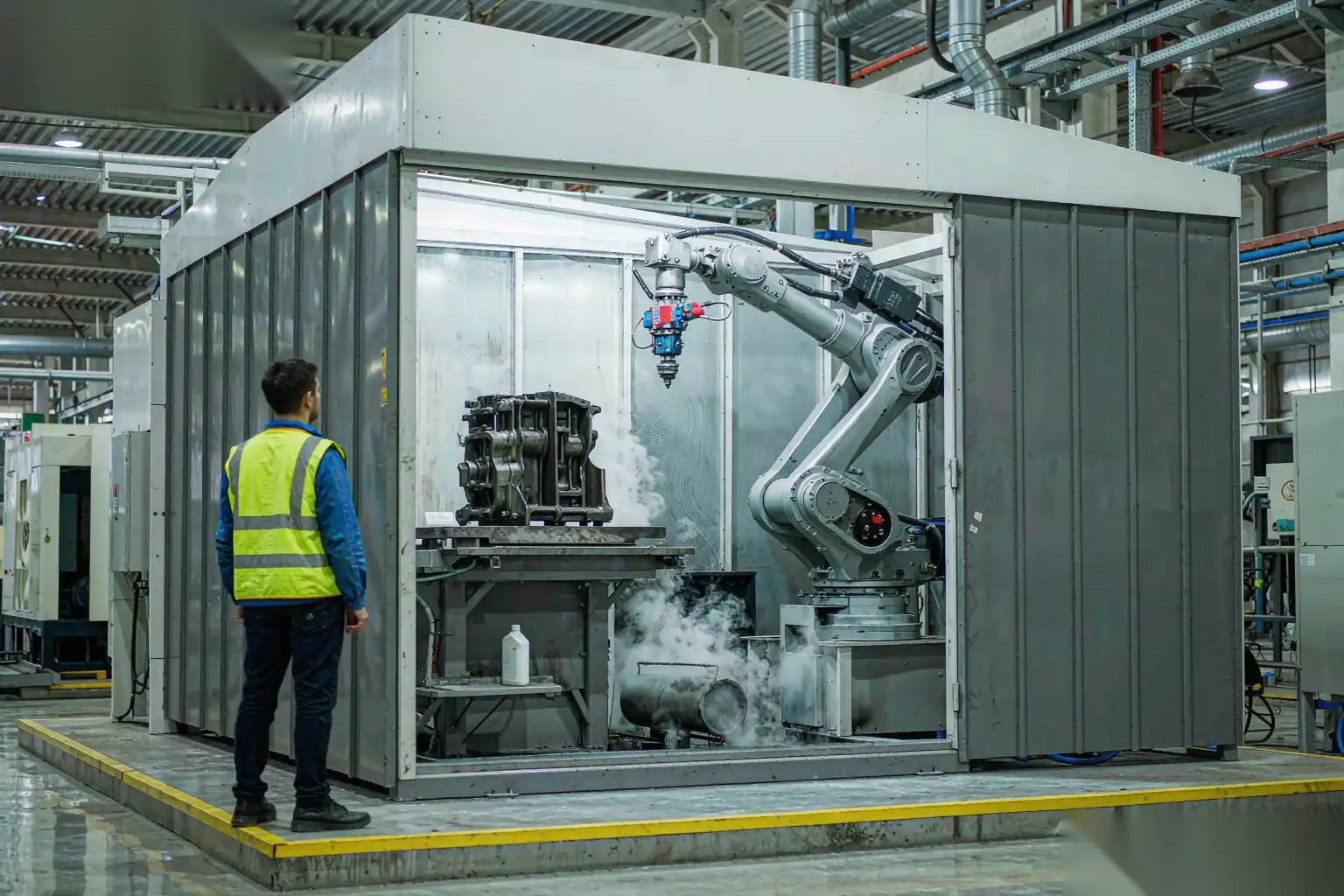
DZ Machinery builds six-axis robotic grinding cells with passive and active force control, automatic tool change, and multi-station rotary tables engineered to your part’s material and tolerance. If your castings are gouging, loading, or failing polish because of force variation, send us your part drawings and we will set the compliance type, the force band, and the fixture stiffness so the cell holds your surface and dimension target without an operator riding the teach pendant.