Robotic Deburring Spindle, Tooling and Abrasive Selection
A robotic deburring cell is only as capable as the spindle, tooling, and abrasive combination mounted on the robot wrist. The robot kinematics and the force controller set the envelope, but the cut quality, cycle time, and tool life are decided at the interface between the rotating tool and the cast edge. Get that interface wrong and you either leave burrs, gouge the part, or burn through tools every few hundred pieces. This article is a working reference for selecting spindles, tooling, and abrasives for aluminum and zinc die castings, drawn from how we configure DZ Smart Manufacturing deburring cells on production floors.
Spindle types and how we choose them
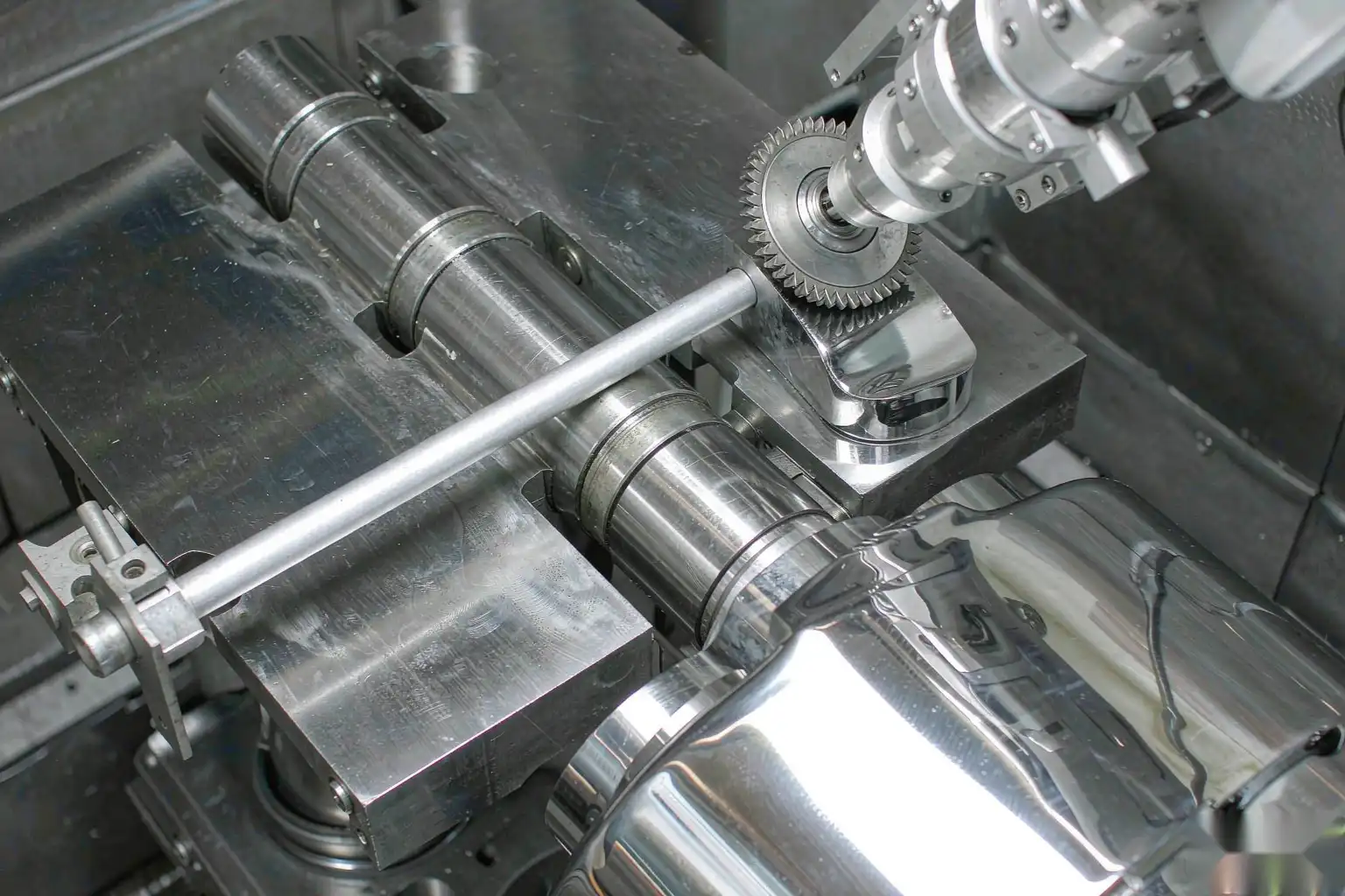
The spindle is the power source at the tool. For deburring castings we work with three families, each with a distinct operating window.
Electric high-speed spindles run from roughly 20,000 to 60,000 rpm and deliver controlled torque through a servo or brushless drive. They suit small burrs, fine edges, and abrasive tools that need a steady surface speed. Because speed is closed-loop, the cut stays consistent as the tool wears. We use these for zinc and thin aluminum where heat and gouging must stay minimal.
Pneumatic spindles are simpler and cheaper, typically 20,000 to 50,000 rpm driven by shop air, but their speed sags under load so cut rate varies with burr size. They are a reasonable choice for light, uniform burrs where the robot path is well controlled and the budget is tight, but they are harder to hold to a spec across a shift.
Compliant spindles and compliance devices are the ones that actually solve variable castings. A compliant head lets the tool float radially and axially so it follows the part contour and holds a set normal force even when the casting is 0.3 mm proud or the fixture is slightly off. For die castings, which always carry some dimensional spread, compliance is not optional for a clean edge; it is the difference between a repeatable burr removal and a random one.
The table below maps spindle choice to the job.
| Spindle type | Speed range | Best for | Limitation |
|---|---|---|---|
| Electric servo, 40-60k rpm | High | Fine edges, zinc, thin Al | Higher cost, needs drive |
| Electric, 20-40k rpm | Medium | General Al deburr | Less finesse on micro-burrs |
| Pneumatic 20-50k rpm | Medium | Light uniform burrs | Speed droop under load |
| Compliant radial/axial | Tool-dependent | Variable castings | Needs tuning of float and force |
RPM, torque and surface speed for aluminum and zinc
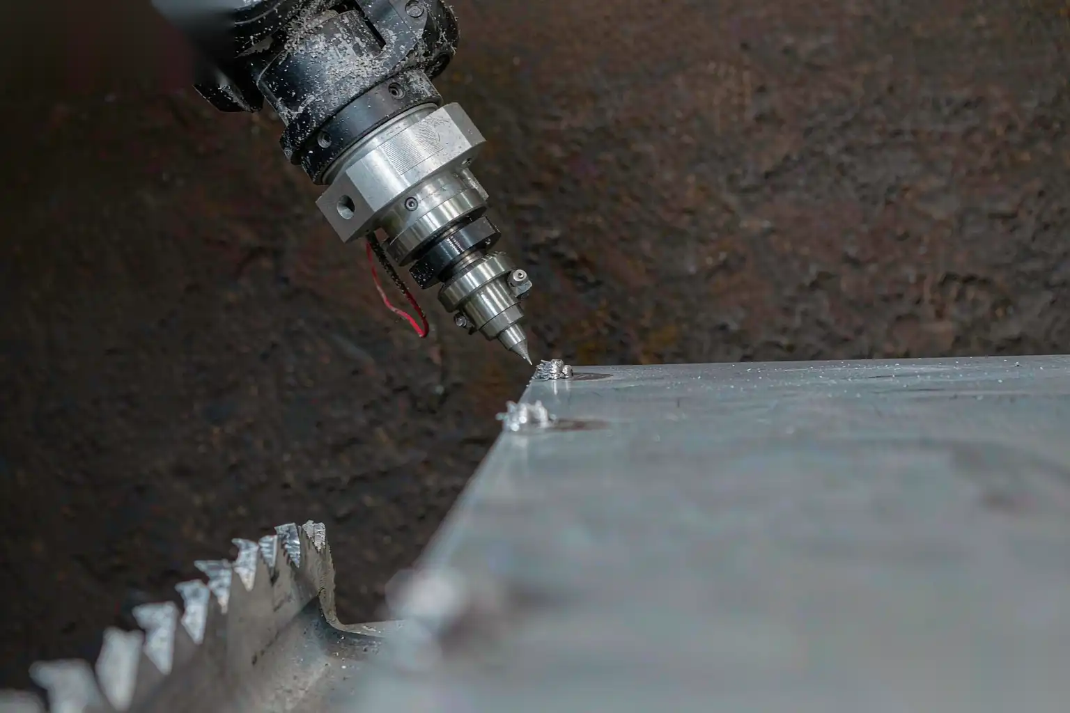
Spindle speed alone means little; what matters is the surface speed at the tool contact, which is a function of rpm and tool diameter. For deburring we target a peripheral speed that cuts cleanly without melting aluminum or smearing zinc.
For aluminum die castings, abrasive burrs and carbide cutters run well around 30 to 60 m per second of peripheral speed. A 6 mm carbide burr at 40,000 rpm gives roughly 12.5 m per second, which is low; the same burr at 60,000 rpm reaches about 19 m per second, still conservative. We push abrasive discs and mounted points to higher surface speeds because the contact area is larger and cooling matters more. Torque must be enough to keep speed up when the tool bites into a thick gate stub; a spindle that drops from 50,000 to 20,000 rpm under load turns a clean cut into a rub that smears aluminum and loads the abrasive.
For zinc, the material is softer and lower melting, so we keep peripheral speed moderate, around 15 to 35 m per second, and favor lighter passes. Too much speed on zinc generates heat that smears the edge and loads the tool with a waxy buildup. A compliant, lower-speed pass with a sharp carbide or a fine abrasive cleans the edge without heating the part.
We always size the spindle torque, not just rpm, against the worst-case burr: a gate vestige on a thick section can demand a brief torque spike. Undersizing torque means the robot slows or the tool stalls, which shows up as a missed burr or a wavy edge.
Tooling selection by burr type
Burr morphology should drive tool choice. We classify cast burrs the way we classify the parts, because the wrong tool either misses the burr or damages the feature.
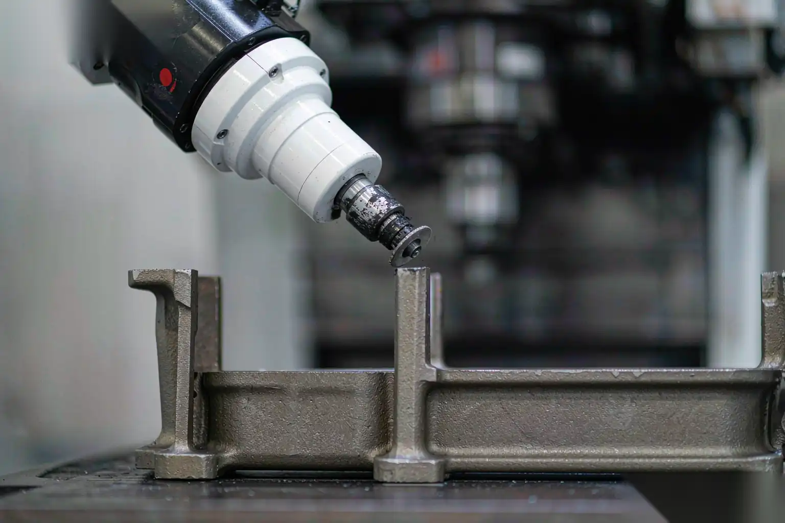
Carbide burrs (rotary files) are the workhorse for hard, discrete burrs: gate stubs, parting-line fins, and ejector-pin flash. We select cut geometry by material: an aluminum-cut (coarse, deep flute) burr clears Al chips without loading, while a standard or fine cut suits zinc and soft alloys. Burr diameter from 3 to 10 mm is chosen by feature access; tight internal edges need a 3 mm ball nose, open faces can take an 8 mm tree or cylinder.
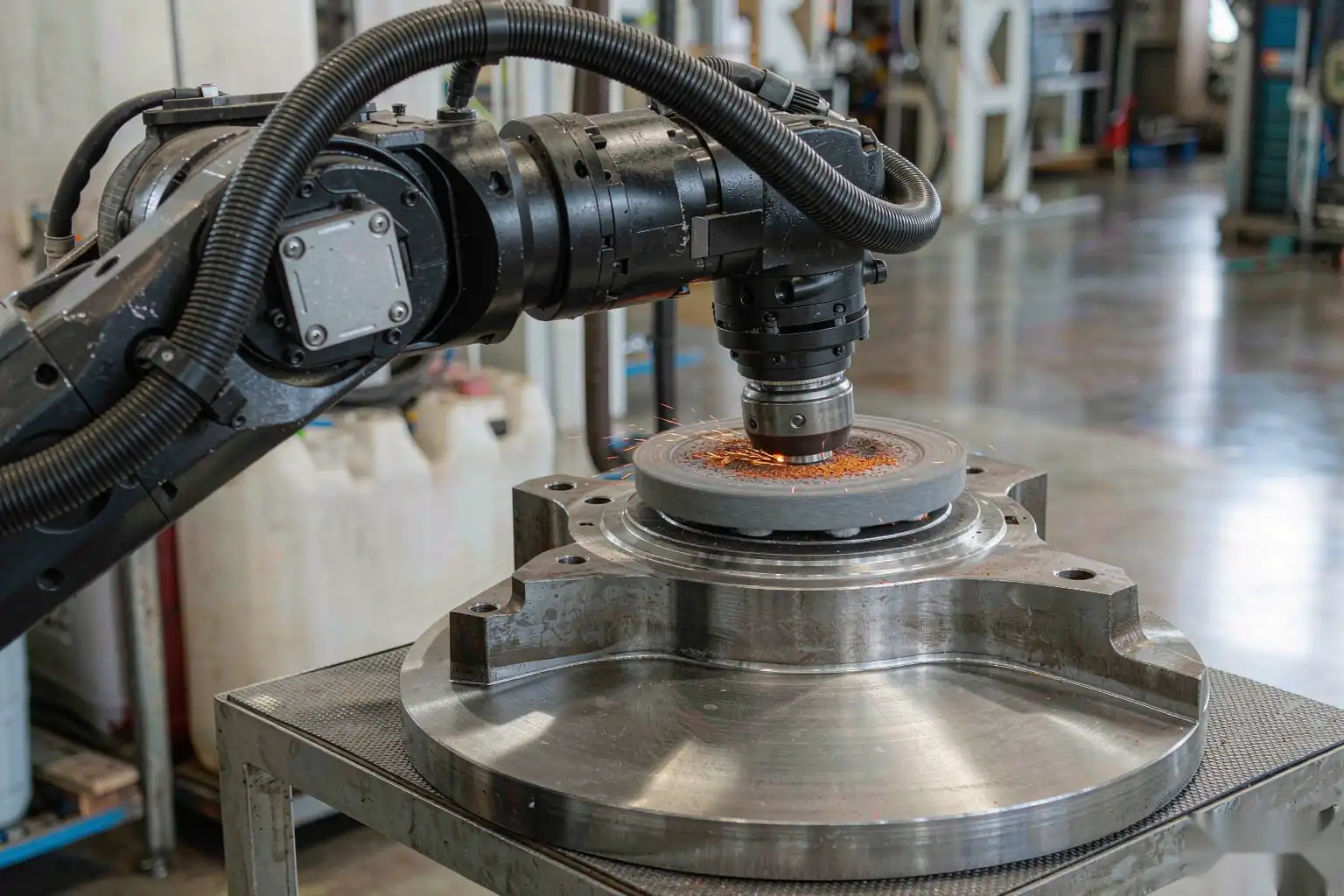
Abrasive discs and mounted points handle edge radii and light fins. A mounted point on a compliant spindle puts a controlled 0.1 to 0.3 mm edge break on a sealing face without removing function. Fiber discs and flap discs work on flat parting lines where a uniform chamfer is wanted.
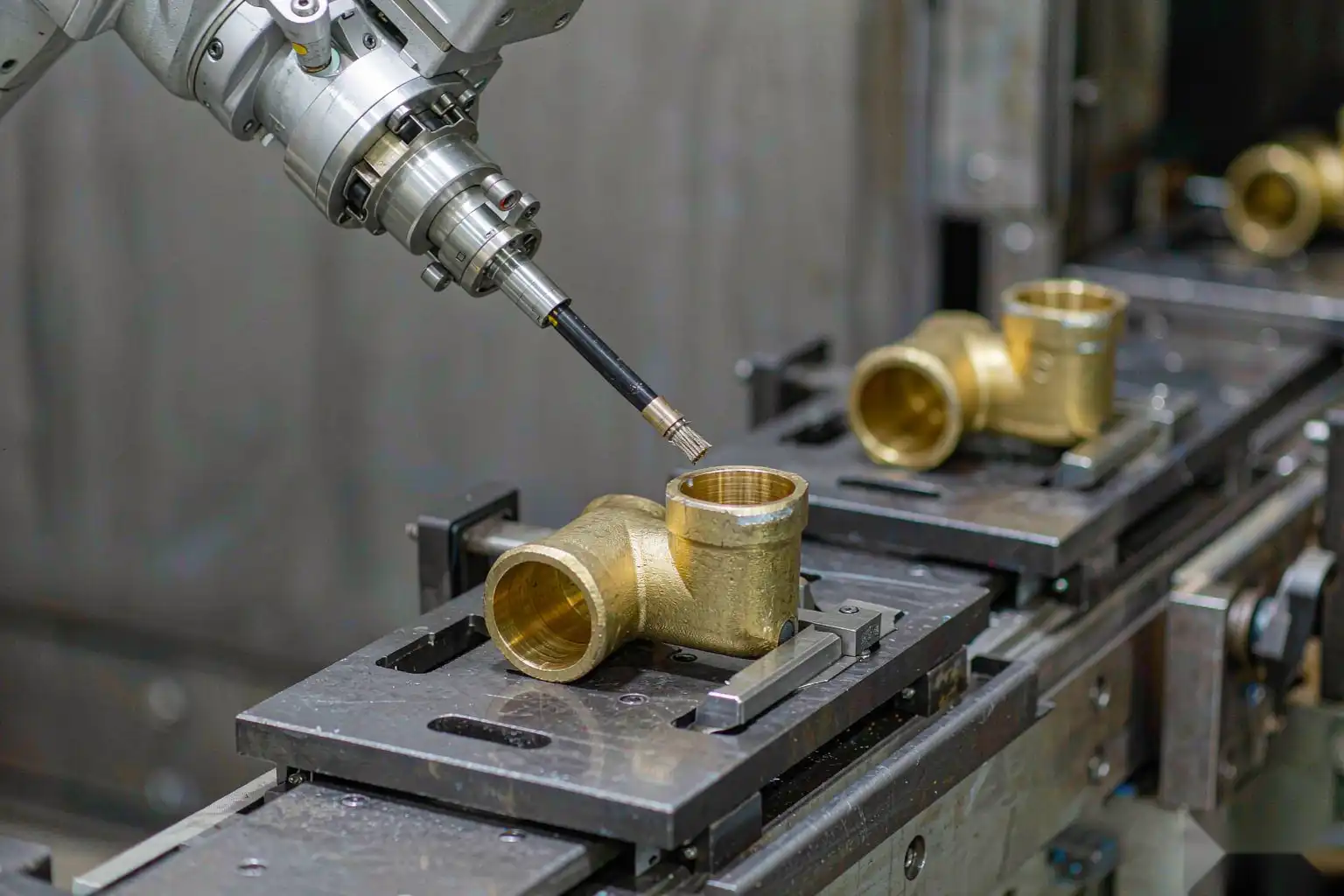
Brushes and Scotch-Brite-style radial wheels are for the final break and the soft deburr. They will not remove a hard gate stub, but they clean micro-flash and hone an edge to a safe, consistent radius without gouging. We use them as the last station so the part leaves with no sharp edge and no tool mark.
The selection logic in our die casting secondary operations guide lines up tool to operation; the deburring-specific method is in our how to deburr aluminum die castings by automation guide.
| Burr type | Tool | Notes |
|---|---|---|
| Gate stub, thick | Carbide burr, aluminum cut | High torque, low feed |
| Parting-line fin | Mounted point or flap disc | Compliant follow |
| Ejector flash | Carbide or fine abrasive | Watch pin location |
| Micro-flash, edge break | Radial brush / Scotch-Brite | Final safe radius |
| Internal corner | 3 mm ball nose burr | Access-limited |
Compliance: radial and axial float to follow variable castings
Die castings are not identical part to part. Fill variation, thermal drift, and fixture repeatability leave the actual edge somewhere in a band, often plus or minus 0.2 to 0.5 mm on a non-machined face. A rigid tool that is programmed to a nominal edge will, on a proud part, gouge; on a shy part, miss the burr. Compliance closes that gap.
Radial float lets the tool move sideways to stay on the contour. We tune the float stiffness so the tool returns to the surface after crossing a step but does not wander under its own spring. Axial float lets the tool retract along its axis when it meets a high spot, protecting the part and the tool. The combination, driven by a force setpoint, keeps normal force roughly constant across the band.
The force setpoint is the real control variable. For aluminum edge breaking we hold around 10 to 30 N of normal force depending on the tool and the edge; for zinc, 5 to 20 N. Too high and the tool digs; too low and it skips. We tune this on the first articles with a force trace, not by eye, because the acceptable window is narrow on a visible edge.
Compliance also protects tool life. A rigid hit on a proud edge spikes load and chips the carbide; a compliant pass spreads the load and the tool lasts. On a production cell this is the difference between changing tools every shift and every few days.
Coolant, air blast and swarf management
Deburring generates heat and chips, and both need handling or the process degrades.
Air blast is the default for most deburring. A continuous air jet at the cut zone blows chips away from the tool and the part, keeps the abrasive from loading, and lets the operator or vision system see the edge. We size the nozzle to put a focused stream right at contact, typically 3 to 6 bar, and route the exhaust through the cell dust collection.
Mist or flood coolant is used when the cut is aggressive or the part is heat-sensitive. For aluminum, a light mist reduces smearing and extends abrasive life on long runs; for zinc, we avoid wet cutting where corrosion is a risk and prefer dry air-blast with a rust-inhibiting post-wipe if the part will sit before finishing.
Swarf handling is a safety and quality item. Aluminum fines are a dust-explosion concern above certain concentrations, so the cell runs negative-pressure dust collection sized to the generation rate, with spark detection where the volume justifies it. Zinc and brass fines are less hazardous but still need collection so they do not contaminate the floor or the next part. Our robotic cell OEE and uptime improvement guide covers how dust and tool changes feed into availability.
Changeover, tool life and program structure
A deburring cell earns its keep on mixed runs only if changeover is fast and tool life is predictable.
Tool life is tracked by count and by wear, not by calendar. A carbide burr on aluminum gates may cut 5,000 to 20,000 edges before the flute dulls, depending on burr hardness and coolant; an abrasive point wears faster, often 1,000 to 5,000 touches. We set a replacement count with margin and let the force controller flag drift, so a worn tool is swapped before it starts missing burrs.
Automatic tool change multiplies this. A DZ cell with a tool rack can swap from a carbide burr to a brush in seconds, letting one robot run multiple stations on one part or switch families with a recipe change. The program stores tool offsets per station so the force setpoint and path adapt when the tool changes.
Changeover between part families is mostly a fixture and recipe swap. We design fixtures with quick-locate dowels and pneumatic clamps so a new part is seated in the same repeatable frame, and the robot recipe calls the right tool sequence. A well-set cell changes family in 10 to 30 minutes including first-article check.
Integration in a DZ deburring cell with fixtures
The spindle and tool are mounted on a 6-axis robot, but the cell is defined by how it holds and presents the part. Our typical layout:
- A two- or four-station rotary table with pneumatic or hydraulic fixtures that locate the casting on machined or cast datum features.
- The robot presents the tool to the edge with a compliant head, running the force setpoint and the tool sequence from the recipe.
- A vision or probe check on the first piece confirms the edge band before the run starts, and periodic checks keep the force trace in window.
- Dust collection, guarding, and a light curtain keep the operator safe and the floor clean.
- Downstream, the part passes to a washing or inspection station so finishing labor sees a clean, burr-free component.
Fixture design matters as much as the spindle. The part must be held so the burr edge is accessible and so vibration under the cut is minimal; a chattering fixture ruins edge quality regardless of tool. We locate on stable datum and clamp away from the edge being cut, and we keep the fixture face clear of the tool path with margin for the compliant float.
Matching tool to removal rate and cycle time
Cycle time is the product of path length, feed rate, and the number of stations. The tool sets the feed rate ceiling: a sharp carbide at the right surface speed can take a fast pass, while a loaded brush must move slowly. We compute removal rate from burr volume and target cycle, then pick the tool that meets it with margin.
A practical example: a zinc lever with a 1.5 mm gate stub and a 0.3 mm parting fin. The gate needs a carbide burr at roughly 40,000 rpm and 15 N force, fed at 200 to 400 mm per minute, taking about 4 to 8 seconds. The fin breaks with a radial brush at 30 N for 2 to 3 seconds. Total deburr near 8 to 15 seconds per part, which on a two-station table gives a cell throughput of roughly 250 to 500 pieces per hour depending on fixture load time.
We balance the stations so no single tool is the bottleneck. If the carbide burr dominates, we add a second burr station or split the path across two robots; if the brush dominates, we speed it or add a station. The goal is a balanced line where the robot and the fixtures, not the tool, set the pace.
Selecting a spindle, tooling, and abrasive for cast aluminum and zinc is an engineering decision, not a catalog pick. Match spindle speed and torque to the burr, select the tool by burr morphology, add compliance so the edge is followed part to part, and manage heat and swarf so the cell stays safe and consistent. DZ Machinery builds these robotic deburring, grinding, and polishing cells with compliant spindles, automatic tool change, and fixture packages tuned to your casting; if you have part drawings and a target cycle time, our engineering team can specify the spindle, tool sequence, and cell layout for your line.